EP0687653B1 - Verfahren und Anlage zur Aufbereitung von Abfall aus Senkgruben - Google Patents
Verfahren und Anlage zur Aufbereitung von Abfall aus Senkgruben Download PDFInfo
- Publication number
- EP0687653B1 EP0687653B1 EP19950401427 EP95401427A EP0687653B1 EP 0687653 B1 EP0687653 B1 EP 0687653B1 EP 19950401427 EP19950401427 EP 19950401427 EP 95401427 A EP95401427 A EP 95401427A EP 0687653 B1 EP0687653 B1 EP 0687653B1
- Authority
- EP
- European Patent Office
- Prior art keywords
- tank
- lagooning
- efficiency
- installation according
- treatment
- Prior art date
- Legal status (The legal status is an assumption and is not a legal conclusion. Google has not performed a legal analysis and makes no representation as to the accuracy of the status listed.)
- Expired - Lifetime
Links
- 238000009434 installation Methods 0.000 title claims description 55
- 238000000034 method Methods 0.000 title description 18
- 230000008569 process Effects 0.000 title description 16
- 239000002699 waste material Substances 0.000 title description 14
- 239000000463 material Substances 0.000 claims description 30
- 239000010791 domestic waste Substances 0.000 claims description 20
- 238000000746 purification Methods 0.000 claims description 16
- 230000029087 digestion Effects 0.000 claims description 10
- 238000003860 storage Methods 0.000 claims description 9
- XLYOFNOQVPJJNP-UHFFFAOYSA-N water Substances O XLYOFNOQVPJJNP-UHFFFAOYSA-N 0.000 claims description 8
- 230000005791 algae growth Effects 0.000 claims description 6
- 238000012545 processing Methods 0.000 claims description 5
- 238000011144 upstream manufacturing Methods 0.000 claims description 5
- 238000001035 drying Methods 0.000 claims description 4
- 239000006228 supernatant Substances 0.000 claims description 3
- 239000000725 suspension Substances 0.000 claims description 3
- 238000003756 stirring Methods 0.000 claims description 2
- 238000007599 discharging Methods 0.000 claims 1
- 239000011343 solid material Substances 0.000 claims 1
- IJGRMHOSHXDMSA-UHFFFAOYSA-N Atomic nitrogen Chemical compound N#N IJGRMHOSHXDMSA-UHFFFAOYSA-N 0.000 description 21
- 239000007787 solid Substances 0.000 description 10
- 229910052757 nitrogen Inorganic materials 0.000 description 9
- 239000000126 substance Substances 0.000 description 9
- 239000002351 wastewater Substances 0.000 description 9
- QVGXLLKOCUKJST-UHFFFAOYSA-N atomic oxygen Chemical compound [O] QVGXLLKOCUKJST-UHFFFAOYSA-N 0.000 description 8
- 239000001301 oxygen Substances 0.000 description 8
- 229910052760 oxygen Inorganic materials 0.000 description 8
- OAICVXFJPJFONN-UHFFFAOYSA-N Phosphorus Chemical compound [P] OAICVXFJPJFONN-UHFFFAOYSA-N 0.000 description 5
- 239000002994 raw material Substances 0.000 description 5
- 239000010865 sewage Substances 0.000 description 5
- 239000010802 sludge Substances 0.000 description 5
- 238000004065 wastewater treatment Methods 0.000 description 5
- 230000000694 effects Effects 0.000 description 4
- 229910052698 phosphorus Inorganic materials 0.000 description 4
- 239000011574 phosphorus Substances 0.000 description 4
- 239000002028 Biomass Substances 0.000 description 3
- ATNHDLDRLWWWCB-AENOIHSZSA-M chlorophyll a Chemical compound C1([C@@H](C(=O)OC)C(=O)C2=C3C)=C2N2C3=CC(C(CC)=C3C)=[N+]4C3=CC3=C(C=C)C(C)=C5N3[Mg-2]42[N+]2=C1[C@@H](CCC(=O)OC\C=C(/C)CCC[C@H](C)CCC[C@H](C)CCCC(C)C)[C@H](C)C2=C5 ATNHDLDRLWWWCB-AENOIHSZSA-M 0.000 description 3
- 238000004519 manufacturing process Methods 0.000 description 3
- 230000003647 oxidation Effects 0.000 description 3
- 238000007254 oxidation reaction Methods 0.000 description 3
- 229910019142 PO4 Inorganic materials 0.000 description 2
- 241001080024 Telles Species 0.000 description 2
- 238000009825 accumulation Methods 0.000 description 2
- 238000004458 analytical method Methods 0.000 description 2
- 230000001580 bacterial effect Effects 0.000 description 2
- 244000052616 bacterial pathogen Species 0.000 description 2
- 230000000721 bacterilogical effect Effects 0.000 description 2
- 239000003153 chemical reaction reagent Substances 0.000 description 2
- 229930002868 chlorophyll a Natural products 0.000 description 2
- 238000005352 clarification Methods 0.000 description 2
- 238000011161 development Methods 0.000 description 2
- 230000018109 developmental process Effects 0.000 description 2
- 230000008030 elimination Effects 0.000 description 2
- 238000003379 elimination reaction Methods 0.000 description 2
- 239000007788 liquid Substances 0.000 description 2
- VNWKTOKETHGBQD-UHFFFAOYSA-N methane Chemical compound C VNWKTOKETHGBQD-UHFFFAOYSA-N 0.000 description 2
- 244000005700 microbiome Species 0.000 description 2
- 239000010815 organic waste Substances 0.000 description 2
- 235000021317 phosphate Nutrition 0.000 description 2
- 150000003013 phosphoric acid derivatives Chemical class 0.000 description 2
- 239000000049 pigment Substances 0.000 description 2
- 238000002203 pretreatment Methods 0.000 description 2
- 238000004062 sedimentation Methods 0.000 description 2
- 238000012546 transfer Methods 0.000 description 2
- UDHXJZHVNHGCEC-UHFFFAOYSA-N Chlorophacinone Chemical compound C1=CC(Cl)=CC=C1C(C=1C=CC=CC=1)C(=O)C1C(=O)C2=CC=CC=C2C1=O UDHXJZHVNHGCEC-UHFFFAOYSA-N 0.000 description 1
- 241000195493 Cryptophyta Species 0.000 description 1
- 238000005273 aeration Methods 0.000 description 1
- 238000000149 argon plasma sintering Methods 0.000 description 1
- 238000006065 biodegradation reaction Methods 0.000 description 1
- 230000005540 biological transmission Effects 0.000 description 1
- 238000007664 blowing Methods 0.000 description 1
- 239000007853 buffer solution Substances 0.000 description 1
- 230000015556 catabolic process Effects 0.000 description 1
- 229930002875 chlorophyll Natural products 0.000 description 1
- 235000019804 chlorophyll Nutrition 0.000 description 1
- 238000004587 chromatography analysis Methods 0.000 description 1
- 238000004140 cleaning Methods 0.000 description 1
- 238000013270 controlled release Methods 0.000 description 1
- 238000010908 decantation Methods 0.000 description 1
- 238000010586 diagram Methods 0.000 description 1
- 238000009826 distribution Methods 0.000 description 1
- 230000004064 dysfunction Effects 0.000 description 1
- 238000005265 energy consumption Methods 0.000 description 1
- 230000005183 environmental health Effects 0.000 description 1
- 238000001704 evaporation Methods 0.000 description 1
- 230000008020 evaporation Effects 0.000 description 1
- 238000002474 experimental method Methods 0.000 description 1
- 238000000605 extraction Methods 0.000 description 1
- 230000002550 fecal effect Effects 0.000 description 1
- 238000000855 fermentation Methods 0.000 description 1
- 230000004151 fermentation Effects 0.000 description 1
- 230000008014 freezing Effects 0.000 description 1
- 238000007710 freezing Methods 0.000 description 1
- 239000007789 gas Substances 0.000 description 1
- 230000008570 general process Effects 0.000 description 1
- 239000004519 grease Substances 0.000 description 1
- 230000012010 growth Effects 0.000 description 1
- 239000010808 liquid waste Substances 0.000 description 1
- 238000005259 measurement Methods 0.000 description 1
- 230000002906 microbiologic effect Effects 0.000 description 1
- 239000005416 organic matter Substances 0.000 description 1
- 238000006213 oxygenation reaction Methods 0.000 description 1
- 238000005192 partition Methods 0.000 description 1
- 230000002572 peristaltic effect Effects 0.000 description 1
- 239000000047 product Substances 0.000 description 1
- 230000005180 public health Effects 0.000 description 1
- 230000000717 retained effect Effects 0.000 description 1
- 239000013049 sediment Substances 0.000 description 1
- 239000010801 sewage sludge Substances 0.000 description 1
- 239000000243 solution Substances 0.000 description 1
- 230000006641 stabilisation Effects 0.000 description 1
- 238000011105 stabilization Methods 0.000 description 1
- 230000002123 temporal effect Effects 0.000 description 1
- 238000009423 ventilation Methods 0.000 description 1
- 230000003442 weekly effect Effects 0.000 description 1
Images




Classifications
-
- C—CHEMISTRY; METALLURGY
- C02—TREATMENT OF WATER, WASTE WATER, SEWAGE, OR SLUDGE
- C02F—TREATMENT OF WATER, WASTE WATER, SEWAGE, OR SLUDGE
- C02F3/00—Biological treatment of water, waste water, or sewage
- C02F3/02—Aerobic processes
- C02F3/12—Activated sludge processes
- C02F3/1236—Particular type of activated sludge installations
- C02F3/1257—Oxidation ditches
-
- C—CHEMISTRY; METALLURGY
- C02—TREATMENT OF WATER, WASTE WATER, SEWAGE, OR SLUDGE
- C02F—TREATMENT OF WATER, WASTE WATER, SEWAGE, OR SLUDGE
- C02F3/00—Biological treatment of water, waste water, or sewage
- C02F3/02—Aerobic processes
- C02F3/12—Activated sludge processes
- C02F3/14—Activated sludge processes using surface aeration
- C02F3/18—Activated sludge processes using surface aeration the aerator having a horizontal axis
-
- C—CHEMISTRY; METALLURGY
- C02—TREATMENT OF WATER, WASTE WATER, SEWAGE, OR SLUDGE
- C02F—TREATMENT OF WATER, WASTE WATER, SEWAGE, OR SLUDGE
- C02F3/00—Biological treatment of water, waste water, or sewage
- C02F3/28—Anaerobic digestion processes
-
- C—CHEMISTRY; METALLURGY
- C02—TREATMENT OF WATER, WASTE WATER, SEWAGE, OR SLUDGE
- C02F—TREATMENT OF WATER, WASTE WATER, SEWAGE, OR SLUDGE
- C02F3/00—Biological treatment of water, waste water, or sewage
- C02F3/30—Aerobic and anaerobic processes
-
- C—CHEMISTRY; METALLURGY
- C02—TREATMENT OF WATER, WASTE WATER, SEWAGE, OR SLUDGE
- C02F—TREATMENT OF WATER, WASTE WATER, SEWAGE, OR SLUDGE
- C02F3/00—Biological treatment of water, waste water, or sewage
- C02F3/32—Biological treatment of water, waste water, or sewage characterised by the animals or plants used, e.g. algae
-
- Y—GENERAL TAGGING OF NEW TECHNOLOGICAL DEVELOPMENTS; GENERAL TAGGING OF CROSS-SECTIONAL TECHNOLOGIES SPANNING OVER SEVERAL SECTIONS OF THE IPC; TECHNICAL SUBJECTS COVERED BY FORMER USPC CROSS-REFERENCE ART COLLECTIONS [XRACs] AND DIGESTS
- Y02—TECHNOLOGIES OR APPLICATIONS FOR MITIGATION OR ADAPTATION AGAINST CLIMATE CHANGE
- Y02W—CLIMATE CHANGE MITIGATION TECHNOLOGIES RELATED TO WASTEWATER TREATMENT OR WASTE MANAGEMENT
- Y02W10/00—Technologies for wastewater treatment
- Y02W10/10—Biological treatment of water, waste water, or sewage
Definitions
- the invention relates to a treatment installation. household organic waste. It also relates to its use for treatment domestic waste materials. More specifically, the invention relates to the treatment of waste materials domestic mainly from septic tanks, watertight pits, and grease traps.
- Document FR-A-2 637 583 thus relates to a process and installation for wastewater treatment.
- the purification installation includes a container with chambers which is subdivided, by partitions, into different sections for preliminary purification, treatment biological or chemical, intermediate purification and / or final wastewater.
- Each section has several rooms that can be connected together in an order any to select according to the quantity and the nature of the wastewater to be treated.
- the installation also includes at least one device in the preliminary treatment area, intermediate and final purification, intended for dispose of the sewage sludge deposited there.
- Document FR-A-2 590 246 relates to a device oxygenation of natural lagoon effluents, in particular for pre-treatment or passage between basins stabilization.
- the work must include a conduit effluent inlet, an effluent outlet pipe and an upstream effluent level adjustment valve.
- This device includes a device blowing air into the effluent outlet pipe.
- Document FR-A-2,585,696 relates to an apparatus for the treatment of waste water by micro-organisms anaerobic fixed on supports. These measures has a closed vertical enclosure having an axis rotating central, equipped at its base with means for entry waste water to be treated, at its upper part, means for the outlet of treated water and the evacuation of fermentation gas produced.
- This enclosure also has a superposition of anaerobic microorganisms, some animated with a rotational movement, the others fixed.
- This device can be connected to one or more septic tanks thus eliminating any risk of clogging and minimizing sludge production while achieving significant purification yields.
- this purification is anaerobic and not aerobic.
- the document EP-A-0 474 296 relates to an apparatus for the purification of waste water.
- This device has a tank comprising a primary circulation system liquid, an outlet and an effluent inlet, connected to the tank, a propulsion device to make circulate the liquid in the circulation system and simultaneously ventilate it.
- the tank is further provided with a denitrification space connected to the rest of the tank by an entry and an exit.
- the effluent inlet is connected to the denitrification space.
- a secondary circulation system is also formed in this denitrification space and has its own propulsion device.
- Document DE-A-2 136 871 concerns a station compact biological treatment plant with aerobic treatment comprising two floors.
- the station consists of a tank open towards the top with in its upper area a preliminary clarification or pre-accumulation and, in its lower part, a sludge digestion chamber.
- the station also includes an accumulation chamber interior and a central final clarification chamber, the rooms being in connection with each other hydrostatically via openings which are large enough to allow water to flow worn out.
- Document DE-A-3 028 039 relates to a sewage treatment plant comprising a oxidation pit following a digestion chamber.
- the oxidation pit is located above the chamber.
- the invention therefore relates to an installation of treatment of domestic waste materials by organic which overcomes the disadvantages encountered by those described in the state of the art.
- the subject of the invention is such a installation capable of serving as a processing unit proximity, to be inexpensive and easily manageable.
- Another object of the present invention is a such an installation which allows the discharge of an effluent having physico-chemical characteristics and microbiological similar to that of used water domestic and therefore treatable by treatment plants conventional collective.
- the discharge of effluents treaties can be done during off-peak hours (in terms of polluting load allowed in stations conventional treatment), at night, for example.
- Another object of the present invention is a such installation, the implementation of which avoids sedimentation in the high-yield lagoon.
- Another object of the present invention is a such an installation which allows to decentralize into permanently the high yield lagoon solid.
- Another object of the present invention is a such an installation, the implementation of which allows elimination and not a transfer of pollution, MES (suspended matter) in the outlet effluent being essentially biomass algal, the purification rates obtained therefore allowing a rejection entirely compatible with treatment in classic collective wastewater treatment plant.
- MES suspended matter
- Another object of the present invention is a such an installation which does not require pre-treatment processes, addition of reagents, aeration artificial.
- the said septic tank (1) and high-performance lagoon (2) being in parallel so that the raw materials suspended in the high-performance lagoon are decanted and digested in the septic tank and the supernatant of the septic tank is discharged into the lagoon, the area in the high-performance lagoon (2) being between 100 and 500 m 2 for a treatment of 1 m 3 / day of domestic waste materials.
- the material processing facility domestic emptying by biological means also includes the following features, taken alone, optional or in combination: the lagoon high efficiency includes at least one means of improving algal growth; the means of improving the algal growth includes a means to create and maintain some current in the high lagoon basin yield; the installation includes, upstream of the high efficiency lagoon, at least one storage tank intended to receive waste materials from sewage trucks; the installation further includes, in downstream of the decantation-digestion septic tank, a bed drying.
- the invention also relates to the use of a sewage treatment plant domestic biologically, according to the invention, for the treatment of domestic waste materials.
- the decantation-digestion process in a reactor or a septic tank is also well known to the skilled person.
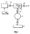
- the septic tank 1 used as decanter-digester is placed in parallel with the high efficiency lagooning 2 and not in series as is done classically.
- suspended solids from raw effluents anaerobes entering the basin change in nature chemical and biological: they are oxidized and transformed partly in micro-algae and bacterial flocs.
- the septic tank 1 is placed in parallel with the high efficiency 2. So the suspended solids that are in the high-yield lagoon 2 are decanted and digested in this septic tank 1 and the supernatant is discharged into the high efficiency lagoon 2 itself.
- the high-performance lagoon 2 includes at minus a means of improving algal growth 3.
- a such means is in particular in the form of a means intended to create and maintain a certain current in the high efficiency lagoon 2.
- this means for creating and maintain a certain current in the lagoon high efficiency is a paddle wheel 3 or equivalent.
- the installation of the present invention comprises also, upstream of the high-yield lagoon 2, at least one storage tank 5 intended to receive the waste materials from sewage trucks.
- the installation according to the present invention also includes, downstream the septic tank of decantation-digestion, a drying bed 7.
- FIG. 2 The experimental installation is illustrated in Figure 2. It consists, from upstream to downstream, of four storage tanks (unit volume: 4 m 3 ) intended to receive the emptying materials from the sewer trucks. One of the four tanks is fitted with a peristaltic pump supplying the system. The raw materials are treated in two so-called "high-yield" lagoon basins (hereinafter called basins A and B). Each basin has an area of 48 m 2 and a depth of 0.30 to 0.45 m. A power distribution system by swinging arm guarantees an equivalent incoming flow in the two basins. In each basin a paddle wheel (chain transmission) makes it possible to create and maintain a certain current.
- a paddle wheel chain transmission
- basin B One of the basins is provided as a witness (basin B), the other (basin A) to be provided in parallel with a anaerobic digester, in particular of the type described in FR-B- 2,596,437.
- the feed rate was set at 100 liters of emptying materials / J. basin.
- Table 1 shows the loads admitted into the basins during a year of experimentation; The organic charges applied for urban wastewater in a high-efficiency lagoon (LHR) and in a traditional lagoon are also reported.
- LHR high-efficiency lagoon
- the admissible loads in an LHR can be modulated according to the season (the ratio can be 1 to 5 from winter to summer).
- Table 2 presents the characteristics of waste materials (average, minimum, maximum, number of samples taken: n).
- the temperatures range from 0 ° C (freezing of the basins) to 28 ° C, the average being 17 ° C.
- the pH predominantly basic, varies between 6.9 and 8.4, so lagooning constitutes an excellent buffer system.
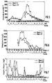
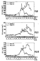
- the chlorophyll a (fig. 5) and pheopigments (fig. 6) contents ranging from a few ⁇ g / l to more than 10 mg / l (basin A) are comparable to those observed during the treatment of urban wastewater by high-efficiency lagooning. So there is really a biological purification carried out by an algae-bacteria complex, the former providing the oxygen necessary for the development of the latter.
- the content of dissolved O 2 (fig. 7) is however relatively low compared to urban wastewater treatment.
- the settling digestion tank therefore has a role important for the proper functioning of the system.
- High-performance tanks accept grades high in total nitrogen which, on a filtered sample, is effect close to 30 mg / l on average (total nitrogen on the raw sample essentially represents the biomass algal).
- Table 3 presents the performance of the process calculated on the means of the last 70 days of experimentation (days 341 to 411).
- the output from basin A (reference basin with pit in parallel) is compared to the input (raw drain material), during the same period.
- Purification performance of the installation according to the invention ENTRY (Raw materials)
- EXIT (Basin A) Yield avg. min. max. not avg. min. max.
- Table 4 shows the bacterial loads recorded during the first 240 days of operation of the system (the analyzes were then stopped). Purification performance of the installation according to the invention (bacteriological parameters) ENTRY (Raw materials) EXIT (Basin A) Abatement avg. min. max. not avg. min. max.
- the pit therefore makes it possible to considerably reduce the load of solid and organic matter within the high efficiency pool. Furthermore, the digestion of organic solids highlighted by the increase in soluble COD accelerates the general process of biodegradation (soluble products are more easily assimilable). The paralleling of this pit is therefore essential for the proper functioning of the installation.
- Table 6 shows the efficiency of the decantation-digestion septic tank by comparing the effluents from the outlet of tanks A (with tank) and B (without tank) from the start of the tank (day 260 to 411). Influence of the pit on the operation of the installation BASIN A BASIN B Efficiency% avg. min. max. not avg. min. max. not MES (mg / l) 6530 2100 20100 20 25210 15200 49700 19 87 Gross COD (mg / l) 5082 480 19140 21 25495 16563 37951 19 87 Filtered COD (mg / l) 540 188 876 21 1056 666 1682 19 68
- the MES in the outlet effluent being mainly algal biomass, purification rates obtained allow rejection entirely compatible with a treatment in a conventional collective wastewater treatment plant.
- the installation according to the invention works without pretreatment, without adding reagents, without artificial ventilation.
- the sludge produced is essentially algal and are methanised in the pit. During their eventual extraction, so they will be highly mineralized (stabilized).
- the feed rates are as they are, in our region and during the highest grade part of year, offset by evaporation, so there is practically no discharge during the summer periods.
- the installation according to the invention is suitable actually if it is done as multiples proximity stations available to emptiers coupled with the existing treatment plants of small and medium towns.
Landscapes
- Life Sciences & Earth Sciences (AREA)
- Engineering & Computer Science (AREA)
- Microbiology (AREA)
- Water Supply & Treatment (AREA)
- Hydrology & Water Resources (AREA)
- Environmental & Geological Engineering (AREA)
- Biodiversity & Conservation Biology (AREA)
- Chemical & Material Sciences (AREA)
- Organic Chemistry (AREA)
- Biotechnology (AREA)
- Botany (AREA)
- Purification Treatments By Anaerobic Or Anaerobic And Aerobic Bacteria Or Animals (AREA)
- Treatment Of Water By Oxidation Or Reduction (AREA)
- Treatment Of Biological Wastes In General (AREA)
Claims (14)
- Aufbereitungsanlage von Haushaltsschmutzstoffen auf biologischem Wege, dadurch gekennzeichnet, dass sie umfasst :mindestens eine Klärgrube (1) zur Beseitigung des grössten Teils der Feststoffe, wobei die Klärgrube (1) ein Fassungsvermögen von 30 m2 aufweist für eine Aufbereitung von 1m3/Tag Haushaltsschmutzstoffen ;mindestens ein Hochleistungs-Kollektorbecken (2) ; wobei die besagte Klärgrube (1) und das besagte Hochleistungs-Kollektorbecken (2) parallel zueinander angeordnet sind, so dass die sich im Hochleistungs-Kollektorbecken (2) in Suspension befindlichen Rohstoffe in der Klärgrube geklärt und zersetzt werden, und dass die an der Oberfläche der Klärgrube schwimmenden Stoffe in das Kollektorbecken zurückgeführt werden, wobei die Oberfläche des Hochleistungs-Kollektorbeckens (2) zwischen 100 und 500 m2 gross ist für eine Aufbereitung von 1m3/Tag Haushaltsschmutzstoffen.
- Anlage nach Anspruch 1, dadurch gekennzeichnet, dass das Hochleistungs-Kollektorbecken (2) mindestens ein Verbesserungsmittel (3) des Algenwachstums umfasst.
- Anlage nach Anspruch 1 oder 2, dadurch gekennzeichnet, dass das Verbesserungsmittel (3) des Algenwachstums ein Mittel umfasst, um im Hochleistungs-Kollektorbecken einen bestimmten Strom herzustellen und aufrechtzuerhalten.
- Anlage nach einem der Ansprüche 1 bis 3, dadurch gekennzeichnet, dass das Mittel zur Herstellung und Aufrechterhaltung eines bestimmten Stromes im Hochleistungs-Kollektorbecken ein Schaufelrad (3) o.ä. umfasst.
- Anlage nach einem der Ansprüche 1 bis 4, dadurch gekennzeichnet, dass die Geschwindigkeit des Wasserstromes im Hochleistungs-Kollektorbecken (2) etwa 5 bis 80 cm/s für eine Aufbereitung von 1m3/Tag Haushaltsschmutzstoffen beträgt.
- Anlage nach einem der Ansprüche 1 is 5, dadurch gekennzeichnet, dass sie eine Umwälzpumpe (4) für die Klärgrube (1) umfasst, die zwischen dieser Grube und dem Hochleistungs-Kollektorbecken (2) angeordnet ist.
- Anlage nach Anspruch 6, dadurch gekennzeichnet, dass die Umwälzmenge in der Klärgrube (1) zwischen 0,5 und 15m3/h und vorzugsweise 1,3m3/h für eine Aufbereitung von 1m3/Tag Haushaltsschmutzstoffen beträgt.
- Anlage nach einem der Ansprüche 1 bis 7, dadurch gekennzeichnet, dass sie dem Hochleistungs-Kollektorbecken (2) vorgelagert mindestens ein Lagerbecken (5) für die Aufnahme der Haushaltsschmutzstoffe umfasst, die mit Wasserklärfahrzeugen antransportiert werden.
- Anlage nach Anspruch 8, dadurch gekennzeichnet, dass das Lagerbecken (5) mit einer Rührvorrichtung ausgerüstet ist.
- Anlage nach Anspruch 8 oder 9, dadurch gekennzeichnet, dass das Fassungsvermögen des Lagerbeckens (5) etwa 30 m3 für eine Aufbereitung von 1m3/Tag Haushaltsschmutzstoffen beträgt.
- Anlage nach einem der Ansprüche 1 bis 10, dadurch gekennzeichnet, dass das Lagerbecken (5) mit einer Pumpe (6) zur Versorgung des Hochleistungs-Kollektorbeckens (2) ausgerüstet ist.
- Anlage nach einem der Ansprüche 1 bis 11, dadurch gekennzeichnet, dass sie weiters, der Klärgrube (1) nachgelagert, ein Trockenbett (7) umfasst.
- Anlage nach einem der Ansprüche 1 bis 12, dadurch gekennzeichnet, dass sie dem Hochleistungs-Kollektorbecken (2) nachgelagert eine Pumpe (8) für die Entsorgung des aufbereiteten Schadstoffes zu einer kollektiven Reinigungsstation (9) umfasst.
- Verwendung einer Anlage nach einem der Ansprüche 1 bis 13 für die Aufbereitung von Haushaltsschmutzstoffen.
Applications Claiming Priority (2)
| Application Number | Priority Date | Filing Date | Title |
|---|---|---|---|
| FR9407396A FR2721310B1 (fr) | 1994-06-16 | 1994-06-16 | Installation de traitement des matières de vidange domestiques, utilisation d'une telle installation pour le traitement de telles matières. |
| FR9407396 | 1994-06-16 |
Publications (2)
| Publication Number | Publication Date |
|---|---|
| EP0687653A1 EP0687653A1 (de) | 1995-12-20 |
| EP0687653B1 true EP0687653B1 (de) | 1999-09-15 |
Family
ID=9464300
Family Applications (1)
| Application Number | Title | Priority Date | Filing Date |
|---|---|---|---|
| EP19950401427 Expired - Lifetime EP0687653B1 (de) | 1994-06-16 | 1995-06-16 | Verfahren und Anlage zur Aufbereitung von Abfall aus Senkgruben |
Country Status (4)
| Country | Link |
|---|---|
| EP (1) | EP0687653B1 (de) |
| ES (1) | ES2140635T3 (de) |
| FR (1) | FR2721310B1 (de) |
| GR (1) | GR3032165T3 (de) |
Families Citing this family (1)
| Publication number | Priority date | Publication date | Assignee | Title |
|---|---|---|---|---|
| FR2997075B1 (fr) * | 2012-10-24 | 2014-11-28 | Saur | Traitement des eaux usees econome en energie a l'aide de microalgues |
Citations (1)
| Publication number | Priority date | Publication date | Assignee | Title |
|---|---|---|---|---|
| WO1995007862A1 (en) * | 1991-11-20 | 1995-03-23 | Beard Harold J | Mixed liquor wasting system and method |
Family Cites Families (5)
| Publication number | Priority date | Publication date | Assignee | Title |
|---|---|---|---|---|
| US3839198A (en) * | 1971-01-25 | 1974-10-01 | G Shelef | Process for sewage treatment and wastewater reclamation |
| DE2136871A1 (de) * | 1971-07-23 | 1973-02-01 | Boehnke Botho | Automatisch arbeitende zweistufige biologische kompaktklaeranlage |
| AT372061B (de) * | 1980-03-03 | 1983-08-25 | Josef Dipl Ing Schmit | Anlage zur mechanischen und biologischen behandlung von abwasser |
| DE3226797A1 (de) * | 1982-07-17 | 1984-01-26 | Rheinisch-Westfälisches Elektrizitätswerk AG, 4300 Essen | Anlage zur aufzucht von nutzbaren fischen |
| FR2596437B1 (fr) * | 1986-03-25 | 1988-04-08 | Eparco Sa | Fosse septique toutes eaux |
-
1994
- 1994-06-16 FR FR9407396A patent/FR2721310B1/fr not_active Expired - Fee Related
-
1995
- 1995-06-16 ES ES95401427T patent/ES2140635T3/es not_active Expired - Lifetime
- 1995-06-16 EP EP19950401427 patent/EP0687653B1/de not_active Expired - Lifetime
-
1999
- 1999-12-16 GR GR990403249T patent/GR3032165T3/el unknown
Patent Citations (1)
| Publication number | Priority date | Publication date | Assignee | Title |
|---|---|---|---|---|
| WO1995007862A1 (en) * | 1991-11-20 | 1995-03-23 | Beard Harold J | Mixed liquor wasting system and method |
Also Published As
| Publication number | Publication date |
|---|---|
| EP0687653A1 (de) | 1995-12-20 |
| FR2721310B1 (fr) | 1996-08-09 |
| FR2721310A1 (fr) | 1995-12-22 |
| ES2140635T3 (es) | 2000-03-01 |
| GR3032165T3 (en) | 2000-04-27 |
Similar Documents
| Publication | Publication Date | Title |
|---|---|---|
| Moreira et al. | Remediation of a winery wastewater combining aerobic biological oxidation and electrochemical advanced oxidation processes | |
| CN202089861U (zh) | 用于处理和改善水的水处理系统 | |
| Yang et al. | Denitrification performance, biofilm formation and microbial diversity during startup of slow sand filter using powdery polycaprolactone as solid carbon source | |
| FR2762834A1 (fr) | Procede et installation pour le traitement des eaux residuaires et leur application aux effluents vinicoles | |
| WO2009135276A1 (en) | Process for large amounts of wastewater desinfection and treatment, water recycling and utilization of organic and inorganic charges | |
| EP2724988B1 (de) | Energiesparende Abwasseraufbereitung mit Hilfe von Mikroalgen | |
| CN108017234B (zh) | 一种污水处理系统及方法 | |
| WO2003076351A1 (fr) | Procede de traitement des boues de stations d'epuration par voie mycelienne | |
| CN110028210A (zh) | 一种适用于uasb处理垃圾渗滤液的工艺 | |
| Sorenson et al. | Illuminated septic tank–A microalgae assisted onsite wastewater treatment system | |
| FR2835250A1 (fr) | Procede et dispositif de traitement biologique d'effluents aqueux, en vue de leur epuration | |
| EP3026022A1 (de) | Mikro-station zur biologischen reinigung | |
| EP0687653B1 (de) | Verfahren und Anlage zur Aufbereitung von Abfall aus Senkgruben | |
| US20110139713A1 (en) | Method of treatment for waste water using microbialgrowth promoter | |
| WO2007028879A1 (fr) | Procede d'epuration d'eaux usees avec ajout d'agent oxydant | |
| CN103848536A (zh) | 生活垃圾渗滤液处理方法 | |
| JPH08155496A (ja) | 汚泥の消化処理方法及びそのための装置 | |
| CN101362621B (zh) | 一种天然橡胶加工废水的组合技术处理方法 | |
| EP3578521A1 (de) | Aufbereitungsverfahren von abwasser, das mikroschadstoffe pharmazeutischen ursprungs enthält | |
| EP4103521A1 (de) | Phyto-reinigungsverfahren und vorrichtung zum behandeln von abwasser | |
| WO2002048055A1 (fr) | Procede et appareil de traitement biologique d'effluents | |
| FR2893935A1 (fr) | Procede et installation de traitement d'effluents charges en micro-organismes. | |
| EP0884281A1 (de) | Verfahren und Anlage zur Behandlung von organischen Substanzen enthaltenden Abwässern | |
| BE1007883A3 (fr) | Procede de traitement des eaux usees et installation pour sa mise en oeuvre. | |
| WO2002090269A1 (fr) | Reacteur de traitement biologique dans une station d'epuration |
Legal Events
| Date | Code | Title | Description |
|---|---|---|---|
| PUAI | Public reference made under article 153(3) epc to a published international application that has entered the european phase |
Free format text: ORIGINAL CODE: 0009012 |
|
| AK | Designated contracting states |
Kind code of ref document: A1 Designated state(s): ES GR IT PT |
|
| 17P | Request for examination filed |
Effective date: 19960109 |
|
| 17Q | First examination report despatched |
Effective date: 19980602 |
|
| GRAG | Despatch of communication of intention to grant |
Free format text: ORIGINAL CODE: EPIDOS AGRA |
|
| GRAG | Despatch of communication of intention to grant |
Free format text: ORIGINAL CODE: EPIDOS AGRA |
|
| GRAH | Despatch of communication of intention to grant a patent |
Free format text: ORIGINAL CODE: EPIDOS IGRA |
|
| GRAH | Despatch of communication of intention to grant a patent |
Free format text: ORIGINAL CODE: EPIDOS IGRA |
|
| RIN1 | Information on inventor provided before grant (corrected) |
Inventor name: MAUNOIR, SIEGFRIED Inventor name: PHILIP, HERVE Inventor name: PIETRASANTA, YVES Inventor name: SAMBUCCO, JEAN-PIERRE Inventor name: CRABOS, JEAN-LOUIS Inventor name: BONDON, DANIEL |
|
| GRAA | (expected) grant |
Free format text: ORIGINAL CODE: 0009210 |
|
| AK | Designated contracting states |
Kind code of ref document: B1 Designated state(s): ES GR IT PT |
|
| ITF | It: translation for a ep patent filed | ||
| REG | Reference to a national code |
Ref country code: ES Ref legal event code: FG2A Ref document number: 2140635 Country of ref document: ES Kind code of ref document: T3 |
|
| REG | Reference to a national code |
Ref country code: PT Ref legal event code: SC4A Free format text: AVAILABILITY OF NATIONAL TRANSLATION Effective date: 19991214 |
|
| PLBE | No opposition filed within time limit |
Free format text: ORIGINAL CODE: 0009261 |
|
| STAA | Information on the status of an ep patent application or granted ep patent |
Free format text: STATUS: NO OPPOSITION FILED WITHIN TIME LIMIT |
|
| 26N | No opposition filed | ||
| PGFP | Annual fee paid to national office [announced via postgrant information from national office to epo] |
Ref country code: GR Payment date: 20060511 Year of fee payment: 12 |
|
| PGFP | Annual fee paid to national office [announced via postgrant information from national office to epo] |
Ref country code: PT Payment date: 20060616 Year of fee payment: 12 |
|
| PGFP | Annual fee paid to national office [announced via postgrant information from national office to epo] |
Ref country code: IT Payment date: 20060630 Year of fee payment: 12 |
|
| REG | Reference to a national code |
Ref country code: PT Ref legal event code: MM4A Free format text: LAPSE DUE TO NON-PAYMENT OF FEES Effective date: 20071217 |
|
| PG25 | Lapsed in a contracting state [announced via postgrant information from national office to epo] |
Ref country code: PT Free format text: LAPSE BECAUSE OF NON-PAYMENT OF DUE FEES Effective date: 20071217 |
|
| PGFP | Annual fee paid to national office [announced via postgrant information from national office to epo] |
Ref country code: ES Payment date: 20080717 Year of fee payment: 14 |
|
| PG25 | Lapsed in a contracting state [announced via postgrant information from national office to epo] |
Ref country code: GR Free format text: LAPSE BECAUSE OF NON-PAYMENT OF DUE FEES Effective date: 20080104 |
|
| PG25 | Lapsed in a contracting state [announced via postgrant information from national office to epo] |
Ref country code: IT Free format text: LAPSE BECAUSE OF NON-PAYMENT OF DUE FEES Effective date: 20070616 |
|
| REG | Reference to a national code |
Ref country code: ES Ref legal event code: FD2A Effective date: 20090617 |
|
| PG25 | Lapsed in a contracting state [announced via postgrant information from national office to epo] |
Ref country code: ES Free format text: LAPSE BECAUSE OF NON-PAYMENT OF DUE FEES Effective date: 20090617 |