EP0687786A1 - Ferrure pour porte coulissante - Google Patents
Ferrure pour porte coulissante Download PDFInfo
- Publication number
- EP0687786A1 EP0687786A1 EP95107373A EP95107373A EP0687786A1 EP 0687786 A1 EP0687786 A1 EP 0687786A1 EP 95107373 A EP95107373 A EP 95107373A EP 95107373 A EP95107373 A EP 95107373A EP 0687786 A1 EP0687786 A1 EP 0687786A1
- Authority
- EP
- European Patent Office
- Prior art keywords
- sliding door
- running shoe
- opening
- running
- Prior art date
- Legal status (The legal status is an assumption and is not a legal conclusion. Google has not performed a legal analysis and makes no representation as to the accuracy of the status listed.)
- Granted
Links
- 238000003780 insertion Methods 0.000 claims description 4
- 230000037431 insertion Effects 0.000 claims description 4
- 239000011521 glass Substances 0.000 description 3
- 238000009434 installation Methods 0.000 description 2
- 238000005452 bending Methods 0.000 description 1
- 238000004512 die casting Methods 0.000 description 1
- 238000004519 manufacturing process Methods 0.000 description 1
- 238000005259 measurement Methods 0.000 description 1
- 238000007789 sealing Methods 0.000 description 1
Images



Classifications
-
- E—FIXED CONSTRUCTIONS
- E05—LOCKS; KEYS; WINDOW OR DOOR FITTINGS; SAFES
- E05B—LOCKS; ACCESSORIES THEREFOR; HANDCUFFS
- E05B65/00—Locks or fastenings for special use
- E05B65/08—Locks or fastenings for special use for sliding wings
- E05B65/0864—Locks or fastenings for special use for sliding wings the bolts sliding perpendicular to the wings
Definitions
- the invention relates to a sliding door fitting, in particular for sliding glass doors, with a lock for locking the two sliding doors.
- two running shoes are provided which can be moved along a double running rail and each carry a disc, the upper edge of which is guided in a top rail.
- One of the running shoes is equipped with a lock, the bolt of which can be pushed into a bolt receptacle of the other running shoe in the closed position of the two doors in order to lock the doors against one another.
- the running shoes consist of H-shaped profiles that have drives below their crossbar, while the lower edge of the disc is received in the space above the crossbar.
- the lower edge of the running shoes lies below the upper edge of the running rails, so that for inserting and removing the Sliding doors need to be overcome.
- One problem is securing the sliding door when it is closed. On the one hand, a relatively slight lifting of the disks is sufficient to lift the running shoes out of the running rails and, on the other hand, the lifting can also take place in that the disks are elastically bent by external force.
- the opening in the second running shoe is generally only created when the sliding door is installed, in order to be able to close the sliding door without gaps regardless of measurement and manufacturing tolerances.
- the subsequent creation of a non-circular hole requires Skill, experience and a lot of time and also a high level of accuracy.
- the invention has for its object to provide a sliding door fitting that offers a high degree of security against burglary and in which the attachment of the bolt receptacle for the hook bolt is simplified.
- the latch receptacle provided on the second running shoe does not consist of an opening to be created by the fitter.
- the latch receptacle is rather provided in a separate extension, which extends the second running shoe and is detachably attached to it.
- the bolt receptacle can therefore consist of a prefabricated part that is merely screwed onto the second running shoe or attached in some other way. This eliminates the need to create a precisely fitting opening at the installation site.
- the extension piece is a prefabricated part, which can be manufactured, for example, by die casting, whereby a complex shape is possible. At the installation site, the attachment piece is simply mounted on the running shoe, which can be carried out quickly and easily.
- the bolt receptacle for the hook bolt of the lock consists of an insert part which is inserted into a pocket of the second running shoe or the attachment piece.
- the opposite Side walls of the bag each have an opening for the passage of the hook bolt.
- the insert which cooperates with the hook bolt of the lock, can be inserted into the pocket in different orientations, so that the same bolt holder can be used either for the right or the left end of a running shoe.
- the openings in both side walls of the bag allow access to the insert from either side of the extension or the running shoe. By simply repositioning it, the bolt holder can be used for either "right” and "left".
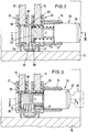
- the sliding door shown in Fig. 1 has a rectangular frame 10, the lower bar carries a double rail 11.
- This double running rail consists of a one-piece profile which is shaped in the manner of an "m” and forms two parallel upstanding running rails 11a and 11b (FIG. 2).
- U-shaped cover rails 12 are arranged along the vertical strips of the frame 10 and contain sealing profiles 13, against which the vertical edges of the two panes 14 and 15 abut.
- the upper edges of the disks 14 and 15 are guided in an upper rail 16 which contains adjustable hold-down devices 17 in the vicinity of the upper corners of the frame 10, which serve on the one hand as a stop brake for the disks 14, 15 and on the other hand secure the disks against being pushed up in the closed state.
- Running shoes 20, 21 run on the double running rail 11 and surround the lower edge of the discs 14 and 15, respectively.
- the running shoes 20, 21 consist of essentially H-shaped profiles, in which roller drives 22 are arranged, the rollers of which roll on the running rails 11a, 11b.
- Each running shoe does not extend over the entire length of a disk 14 or 15.
- the extension 23 extends the running shoe 20 to the length of the disk 14.
- the lock 25 contains a lock cylinder 26 which can be inserted into the cylinder 24 and is pressed outwards by a spring 27.
- the lock 25 contains a hook bolt 29, i.e. a pin which is advanced by pressing in the lock cylinder 26 and has a hook 30 projecting at right angles.
- the pin 29 is rotated, as a result of which the hook 30 is pivoted.
- the hook bolt is guided so that the hook bolt 29 can only be rotated when the lock cylinder 26 is fully inserted.
- An additional lifting safety device 52 in the form of a bracket can be fastened to the running rail 11, through which the hook bolt 29 passes through in the closed position of the running shoes.
- the running shoe 21 is extended to the length of the disk 15 by an extension 31.
- the running shoe 21 consists of an H-shaped profile with two parallel outer walls 32, 33, which are connected by a crossbar 34. At the lower ends of the outer walls 32, 33 there are ribs 35 projecting inwards.
- an extension 36 protruding from the extension 31 is inserted.
- This approach 36 rests on the ribs 35.
- a tensioning element 37 projects through it in the form of a vertical screw, which is tensioned against the crossbar 34 from below.
- the extension piece 31 is firmly attached to the running shoe 21.
- the extension piece 31 has parallel flat outer walls 38, 39, which are flush with the outer walls 32, 33 of the running shoe 21.
- the outer walls 38, 39 are connected to one another by a cross piece 40, the upper side of which runs flush with the cross piece 34 of the running shoe 21. In this way, the lower edge of the disc 15 is received by the running shoe 21 and the extension piece 31, without having to make notches on the lower edge of the disc.
- openings 41 and 42 are provided in the side walls 38, 39 of the extension 31 below the crossbar 40. These openings are so large that the hook bolt 29 fits through with play in the insertion position of its hook 30. Furthermore, the side walls 38, 39 delimit a pocket 43 below the crosspiece 40. In the crosspiece 40 there is an opening 44 through which an insert 45 can be inserted into the pocket 43.
- the insert part 45 consists of a thick disc which has a closed side wall 46 on one side and an opening 47 in the opposite side wall.
- the opening 47 has essentially the same cross section as the front end of the hook bolt 29, so that this end can be pushed through the opening 47 with the hook 30.
- This cross section has the shape of an arch gate.
- the interior 48 of the insert part 45 has a greater length in the sliding direction of the doors than the opening 47, so that undercuts are formed behind the edges of the opening 47, into which the hook 30 of the Hook bolt 29 can penetrate when the hook bolt is rotated about its longitudinal axis by the key 28.
- the length of the insert part 45 is at least about 2 mm smaller than the length of the pocket 43, so that the insert part 45 can freely adjust in the pocket 43 in the longitudinal direction.
- the insert part 45 can be inserted into the extension piece 31 in such a way that the opening 47 of the insert part is located within the one opening 41 of the extension piece 31.
- the opening 47 is smaller than the opening 41 and in each sliding position of the insert part 45 it is in the region of the opening 41.
- an insertion bevel 49 is provided at the edge of the opening 47 and At the front edge of the hook bolt 29 there is also an insertion bevel 50.
- the insert part 45 can be inserted into the pocket 43 in different orientations, namely in the orientation in which the opening 47 is located within the opening 41 and in the opposite orientation, which is denoted by 45 ′, in which the opening 47 is located in the region of the opening 42.
- the same extension 31 with the insert 45 used can be used both for a running shoe in which the lock is arranged on the left end and for a running shoe in which the lock is arranged on the right end. That of openings 41 and 42 that are on the extension 31 is arranged on the outside, that is not opposite the first running shoe 20, is closed by the outer surface 46 of the insert part 45.
- the edge of this opening 41 and 42 forms a handle recess as a handle for moving the relevant door.
- the lock 25 can also be inserted "right” or “left” into the extension 23 or directly into the first running shoe 20, since the cylinder 24 can be inserted into the extension 23 from both sides and is held by the screws 23 a.
- an opening 51 is provided in the bottom of the extension 31 so that the bottom wall does not rub against the running rail in question. However, there are webs on the side of the opening 51 on which the insert part 45 rests. The insert part 45 can therefore only be inserted into the pocket 43 through the opening 44.
Landscapes
- Wing Frames And Configurations (AREA)
- Holders For Apparel And Elements Relating To Apparel (AREA)
- Vehicle Step Arrangements And Article Storage (AREA)
- Purses, Travelling Bags, Baskets, Or Suitcases (AREA)
Applications Claiming Priority (2)
| Application Number | Priority Date | Filing Date | Title |
|---|---|---|---|
| DE9409634U DE9409634U1 (de) | 1994-06-15 | 1994-06-15 | Schiebetürbeschlag |
| DE9409634U | 1994-06-15 |
Publications (2)
| Publication Number | Publication Date |
|---|---|
| EP0687786A1 true EP0687786A1 (fr) | 1995-12-20 |
| EP0687786B1 EP0687786B1 (fr) | 1998-08-12 |
Family
ID=6909851
Family Applications (1)
| Application Number | Title | Priority Date | Filing Date |
|---|---|---|---|
| EP95107373A Expired - Lifetime EP0687786B1 (fr) | 1994-06-15 | 1995-05-16 | Ferrure pour porte coulissante |
Country Status (4)
| Country | Link |
|---|---|
| EP (1) | EP0687786B1 (fr) |
| AT (1) | ATE169712T1 (fr) |
| DE (2) | DE9409634U1 (fr) |
| ES (1) | ES2122388T3 (fr) |
Cited By (5)
| Publication number | Priority date | Publication date | Assignee | Title |
|---|---|---|---|---|
| US6340184B1 (en) | 2000-01-13 | 2002-01-22 | Alan Paul Kuzmich | Security device for sliding doors and windows |
| EP1262626A3 (fr) * | 2001-05-17 | 2003-11-05 | HUWIL-Werke GmbH Möbelschloss- u. Beschlagfabriken | Dispositif comprenant un volet roulant, des rails de guidage et une serrure |
| GB2409233A (en) * | 2003-12-18 | 2005-06-22 | Fullex Locks Ltd | Lock device |
| EP1867813A1 (fr) * | 2006-06-06 | 2007-12-19 | GEBR. WILLACH GmbH | Butée de porte coulissante |
| DE102013217541A1 (de) * | 2013-09-03 | 2015-03-05 | Gebr. Willach Gmbh | Tragsystem für eine Schiebetür, sowie Schiebetür |
Families Citing this family (2)
| Publication number | Priority date | Publication date | Assignee | Title |
|---|---|---|---|---|
| DE20312399U1 (de) * | 2003-08-08 | 2003-11-06 | Gebr. Willach GmbH, 53809 Ruppichteroth | Schloss für Glasschiebetüren |
| FR2952108B1 (fr) * | 2009-11-02 | 2011-12-16 | Adler Sas | Dispositif de verrouillage des portes d'une vitrine |
Citations (4)
| Publication number | Priority date | Publication date | Assignee | Title |
|---|---|---|---|---|
| GB1067938A (en) * | 1964-11-17 | 1967-05-10 | Isobel Rosemary Barnes | Improvements in slidable window assemblies |
| DE2331369A1 (de) * | 1973-06-20 | 1975-01-23 | Voss Kg J | Verschluss fuer laufschuhe, insbesondere solche von glasschiebetueren an schaufenster-vitrinen |
| AU476068B2 (en) * | 1973-07-10 | 1976-01-08 | Lock for slidable doors, windows and the like | |
| WO1985004443A1 (fr) * | 1984-03-27 | 1985-10-10 | Kabushiki Kaisha Hatao | Serrure simplifiee pour porte a double battant |
Family Cites Families (2)
| Publication number | Priority date | Publication date | Assignee | Title |
|---|---|---|---|---|
| DE2842170A1 (de) * | 1978-09-28 | 1980-04-17 | Huwil Werke Gmbh | Hebelriegelschloss, insbesondere fuer schiebetuerschraenke |
| DE8413744U1 (de) * | 1984-05-05 | 1984-10-18 | Pauli + Sohn GmbH, 5220 Waldbröl | Glasschiebetuer-laufschuhschloss mit druckschliesszylinder |
-
1994
- 1994-06-15 DE DE9409634U patent/DE9409634U1/de not_active Expired - Lifetime
-
1995
- 1995-05-16 EP EP95107373A patent/EP0687786B1/fr not_active Expired - Lifetime
- 1995-05-16 AT AT95107373T patent/ATE169712T1/de active
- 1995-05-16 DE DE59503130T patent/DE59503130D1/de not_active Expired - Lifetime
- 1995-05-16 ES ES95107373T patent/ES2122388T3/es not_active Expired - Lifetime
Patent Citations (4)
| Publication number | Priority date | Publication date | Assignee | Title |
|---|---|---|---|---|
| GB1067938A (en) * | 1964-11-17 | 1967-05-10 | Isobel Rosemary Barnes | Improvements in slidable window assemblies |
| DE2331369A1 (de) * | 1973-06-20 | 1975-01-23 | Voss Kg J | Verschluss fuer laufschuhe, insbesondere solche von glasschiebetueren an schaufenster-vitrinen |
| AU476068B2 (en) * | 1973-07-10 | 1976-01-08 | Lock for slidable doors, windows and the like | |
| WO1985004443A1 (fr) * | 1984-03-27 | 1985-10-10 | Kabushiki Kaisha Hatao | Serrure simplifiee pour porte a double battant |
Cited By (5)
| Publication number | Priority date | Publication date | Assignee | Title |
|---|---|---|---|---|
| US6340184B1 (en) | 2000-01-13 | 2002-01-22 | Alan Paul Kuzmich | Security device for sliding doors and windows |
| EP1262626A3 (fr) * | 2001-05-17 | 2003-11-05 | HUWIL-Werke GmbH Möbelschloss- u. Beschlagfabriken | Dispositif comprenant un volet roulant, des rails de guidage et une serrure |
| GB2409233A (en) * | 2003-12-18 | 2005-06-22 | Fullex Locks Ltd | Lock device |
| EP1867813A1 (fr) * | 2006-06-06 | 2007-12-19 | GEBR. WILLACH GmbH | Butée de porte coulissante |
| DE102013217541A1 (de) * | 2013-09-03 | 2015-03-05 | Gebr. Willach Gmbh | Tragsystem für eine Schiebetür, sowie Schiebetür |
Also Published As
| Publication number | Publication date |
|---|---|
| ATE169712T1 (de) | 1998-08-15 |
| DE9409634U1 (de) | 1995-10-19 |
| ES2122388T3 (es) | 1998-12-16 |
| DE59503130D1 (de) | 1998-09-17 |
| EP0687786B1 (fr) | 1998-08-12 |
Similar Documents
| Publication | Publication Date | Title |
|---|---|---|
| DE102011011113B4 (de) | Rahmensystem eines Partikelschutzgitters | |
| DE202022100517U1 (de) | Profilanordnung eines Fensters oder einer Tür mit einem Flügelprofil, insbesondere einem Schiebeflügelprofil | |
| DE9017302U1 (de) | Verschlußgetriebe für ein zweiflügeliges Fenster o.dgl. | |
| EP0718456A1 (fr) | Système de fermeture pour fenêtre, porte etc. | |
| EP3859107A1 (fr) | Porte coulissante | |
| EP0687786B1 (fr) | Ferrure pour porte coulissante | |
| CH642712A5 (de) | Schiebetuerfluegel mit verstellbaren rollentraegern. | |
| EP0856626B1 (fr) | Dispositif de fixation formant pince pour ferrures | |
| EP3859105B1 (fr) | Dispositif de fermeture | |
| DE29601966U1 (de) | Zusatzschloß für Flügel von Türen, Fenstern o.dgl. | |
| EP0572988B1 (fr) | Gâche | |
| EP1580375A2 (fr) | Gâche pour fenêtre ou porte-fenêtres | |
| EP0539672A1 (fr) | Ferrure pour fixation dans une rainure d'un profilé rétréci des deux côtés | |
| DE9114374U1 (de) | Treibstangenbeschlag für Fenster, Türen o.dgl. | |
| EP3816383B1 (fr) | Agencement de porte coulissante | |
| DE69205091T2 (de) | Aushebevorbeugungsvorrichtung für Schiebeflügel, insbesondere einer Tür, eines Fensters oder ähnlichem. | |
| DE19901188C2 (de) | Türblattführung sowie zugehörige Türflügelanordnung, insbesondere für automatische Schiebetüren | |
| DE4342931C1 (de) | Beschlag für eine Klappe oder ein Klappenfenster an einem Wohnwagen | |
| DE69402279T2 (de) | Schiebeflügel | |
| CH620734A5 (en) | Automatic roller-shutter safety device | |
| DE2243916A1 (de) | Kippriegel-verschlussbeschlag fuer kipp-schwenkfluegel-fenster und -tueren od. dgl | |
| DE102015206908A1 (de) | Fenster, Tür oder dergleichen mit einem Beschlag | |
| DE29615631U1 (de) | Sicherungseinrichtung | |
| DE29505071U1 (de) | Widerlager eines Sperrteils an Türen oder Fenstern | |
| DE19502362C2 (de) | Positionierungseinrichtung für Beschlagteile |
Legal Events
| Date | Code | Title | Description |
|---|---|---|---|
| PUAI | Public reference made under article 153(3) epc to a published international application that has entered the european phase |
Free format text: ORIGINAL CODE: 0009012 |
|
| AK | Designated contracting states |
Kind code of ref document: A1 Designated state(s): AT BE CH DE ES FR GB IT LI NL SE |
|
| 17P | Request for examination filed |
Effective date: 19960213 |
|
| GRAG | Despatch of communication of intention to grant |
Free format text: ORIGINAL CODE: EPIDOS AGRA |
|
| 17Q | First examination report despatched |
Effective date: 19970717 |
|
| GRAG | Despatch of communication of intention to grant |
Free format text: ORIGINAL CODE: EPIDOS AGRA |
|
| GRAH | Despatch of communication of intention to grant a patent |
Free format text: ORIGINAL CODE: EPIDOS IGRA |
|
| GRAH | Despatch of communication of intention to grant a patent |
Free format text: ORIGINAL CODE: EPIDOS IGRA |
|
| GRAA | (expected) grant |
Free format text: ORIGINAL CODE: 0009210 |
|
| AK | Designated contracting states |
Kind code of ref document: B1 Designated state(s): AT BE CH DE ES FR GB IT LI NL SE |
|
| REF | Corresponds to: |
Ref document number: 169712 Country of ref document: AT Date of ref document: 19980815 Kind code of ref document: T |
|
| REG | Reference to a national code |
Ref country code: CH Ref legal event code: NV Representative=s name: TROESCH SCHEIDEGGER WERNER AG Ref country code: CH Ref legal event code: EP |
|
| REF | Corresponds to: |
Ref document number: 59503130 Country of ref document: DE Date of ref document: 19980917 |
|
| GBT | Gb: translation of ep patent filed (gb section 77(6)(a)/1977) |
Effective date: 19980922 |
|
| ET | Fr: translation filed | ||
| REG | Reference to a national code |
Ref country code: ES Ref legal event code: FG2A Ref document number: 2122388 Country of ref document: ES Kind code of ref document: T3 |
|
| PLBE | No opposition filed within time limit |
Free format text: ORIGINAL CODE: 0009261 |
|
| STAA | Information on the status of an ep patent application or granted ep patent |
Free format text: STATUS: NO OPPOSITION FILED WITHIN TIME LIMIT |
|
| 26N | No opposition filed | ||
| REG | Reference to a national code |
Ref country code: GB Ref legal event code: IF02 |
|
| PGFP | Annual fee paid to national office [announced via postgrant information from national office to epo] |
Ref country code: SE Payment date: 20110523 Year of fee payment: 17 Ref country code: CH Payment date: 20110525 Year of fee payment: 17 Ref country code: ES Payment date: 20110524 Year of fee payment: 17 Ref country code: FR Payment date: 20110603 Year of fee payment: 17 |
|
| PGFP | Annual fee paid to national office [announced via postgrant information from national office to epo] |
Ref country code: GB Payment date: 20110523 Year of fee payment: 17 Ref country code: BE Payment date: 20110525 Year of fee payment: 17 Ref country code: AT Payment date: 20110520 Year of fee payment: 17 |
|
| PGFP | Annual fee paid to national office [announced via postgrant information from national office to epo] |
Ref country code: NL Payment date: 20120523 Year of fee payment: 18 |
|
| PGFP | Annual fee paid to national office [announced via postgrant information from national office to epo] |
Ref country code: IT Payment date: 20120521 Year of fee payment: 18 |
|
| BERE | Be: lapsed |
Owner name: GEBR. *WILLACH G.M.B.H. Effective date: 20120531 |
|
| PGFP | Annual fee paid to national office [announced via postgrant information from national office to epo] |
Ref country code: DE Payment date: 20120727 Year of fee payment: 18 |
|
| REG | Reference to a national code |
Ref country code: CH Ref legal event code: PL |
|
| REG | Reference to a national code |
Ref country code: SE Ref legal event code: EUG |
|
| REG | Reference to a national code |
Ref country code: AT Ref legal event code: MM01 Ref document number: 169712 Country of ref document: AT Kind code of ref document: T Effective date: 20120516 |
|
| GBPC | Gb: european patent ceased through non-payment of renewal fee |
Effective date: 20120516 |
|
| PG25 | Lapsed in a contracting state [announced via postgrant information from national office to epo] |
Ref country code: CH Free format text: LAPSE BECAUSE OF NON-PAYMENT OF DUE FEES Effective date: 20120531 Ref country code: LI Free format text: LAPSE BECAUSE OF NON-PAYMENT OF DUE FEES Effective date: 20120531 Ref country code: AT Free format text: LAPSE BECAUSE OF NON-PAYMENT OF DUE FEES Effective date: 20120516 |
|
| PG25 | Lapsed in a contracting state [announced via postgrant information from national office to epo] |
Ref country code: SE Free format text: LAPSE BECAUSE OF NON-PAYMENT OF DUE FEES Effective date: 20120517 Ref country code: BE Free format text: LAPSE BECAUSE OF NON-PAYMENT OF DUE FEES Effective date: 20120531 |
|
| REG | Reference to a national code |
Ref country code: FR Ref legal event code: ST Effective date: 20130131 |
|
| PG25 | Lapsed in a contracting state [announced via postgrant information from national office to epo] |
Ref country code: GB Free format text: LAPSE BECAUSE OF NON-PAYMENT OF DUE FEES Effective date: 20120516 Ref country code: FR Free format text: LAPSE BECAUSE OF NON-PAYMENT OF DUE FEES Effective date: 20120531 |
|
| REG | Reference to a national code |
Ref country code: ES Ref legal event code: FD2A Effective date: 20130820 |
|
| PG25 | Lapsed in a contracting state [announced via postgrant information from national office to epo] |
Ref country code: ES Free format text: LAPSE BECAUSE OF NON-PAYMENT OF DUE FEES Effective date: 20120517 |
|
| REG | Reference to a national code |
Ref country code: NL Ref legal event code: V1 Effective date: 20131201 |
|
| PG25 | Lapsed in a contracting state [announced via postgrant information from national office to epo] |
Ref country code: DE Free format text: LAPSE BECAUSE OF NON-PAYMENT OF DUE FEES Effective date: 20131203 |
|
| PG25 | Lapsed in a contracting state [announced via postgrant information from national office to epo] |
Ref country code: IT Free format text: LAPSE BECAUSE OF NON-PAYMENT OF DUE FEES Effective date: 20130516 Ref country code: NL Free format text: LAPSE BECAUSE OF NON-PAYMENT OF DUE FEES Effective date: 20131201 |
|
| REG | Reference to a national code |
Ref country code: DE Ref legal event code: R119 Ref document number: 59503130 Country of ref document: DE Effective date: 20131203 |