EP0687796A1 - Dispositif de déport de sangle - Google Patents
Dispositif de déport de sangle Download PDFInfo
- Publication number
- EP0687796A1 EP0687796A1 EP95401389A EP95401389A EP0687796A1 EP 0687796 A1 EP0687796 A1 EP 0687796A1 EP 95401389 A EP95401389 A EP 95401389A EP 95401389 A EP95401389 A EP 95401389A EP 0687796 A1 EP0687796 A1 EP 0687796A1
- Authority
- EP
- European Patent Office
- Prior art keywords
- bearing
- guide device
- opening
- strap
- rolling member
- Prior art date
- Legal status (The legal status is an assumption and is not a legal conclusion. Google has not performed a legal analysis and makes no representation as to the accuracy of the status listed.)
- Granted
Links
- 238000005096 rolling process Methods 0.000 claims abstract description 21
- 239000004033 plastic Substances 0.000 description 3
- 239000000463 material Substances 0.000 description 2
- 238000004804 winding Methods 0.000 description 2
- 229920004943 Delrin® Polymers 0.000 description 1
- 229910001335 Galvanized steel Inorganic materials 0.000 description 1
- 239000004952 Polyamide Substances 0.000 description 1
- 239000004809 Teflon Substances 0.000 description 1
- 229920006362 Teflon® Polymers 0.000 description 1
- 238000005452 bending Methods 0.000 description 1
- 239000004035 construction material Substances 0.000 description 1
- 230000000694 effects Effects 0.000 description 1
- 239000008397 galvanized steel Substances 0.000 description 1
- 238000004519 manufacturing process Methods 0.000 description 1
- 239000002184 metal Substances 0.000 description 1
- 238000000465 moulding Methods 0.000 description 1
- 238000009304 pastoral farming Methods 0.000 description 1
- 229920002647 polyamide Polymers 0.000 description 1
- 229920000098 polyolefin Polymers 0.000 description 1
- 239000000126 substance Substances 0.000 description 1
Images


Classifications
-
- E—FIXED CONSTRUCTIONS
- E06—DOORS, WINDOWS, SHUTTERS, OR ROLLER BLINDS IN GENERAL; LADDERS
- E06B—FIXED OR MOVABLE CLOSURES FOR OPENINGS IN BUILDINGS, VEHICLES, FENCES OR LIKE ENCLOSURES IN GENERAL, e.g. DOORS, WINDOWS, BLINDS, GATES
- E06B9/00—Screening or protective devices for wall or similar openings, with or without operating or securing mechanisms; Closures of similar construction
- E06B9/56—Operating, guiding or securing devices or arrangements for roll-type closures; Spring drums; Tape drums; Counterweighting arrangements therefor
- E06B9/78—Operating, guiding or securing devices or arrangements for roll-type closures; Spring drums; Tape drums; Counterweighting arrangements therefor for direct manual operation, e.g. by tassels, by handles
-
- E—FIXED CONSTRUCTIONS
- E06—DOORS, WINDOWS, SHUTTERS, OR ROLLER BLINDS IN GENERAL; LADDERS
- E06B—FIXED OR MOVABLE CLOSURES FOR OPENINGS IN BUILDINGS, VEHICLES, FENCES OR LIKE ENCLOSURES IN GENERAL, e.g. DOORS, WINDOWS, BLINDS, GATES
- E06B9/00—Screening or protective devices for wall or similar openings, with or without operating or securing mechanisms; Closures of similar construction
- E06B9/56—Operating, guiding or securing devices or arrangements for roll-type closures; Spring drums; Tape drums; Counterweighting arrangements therefor
- E06B9/78—Operating, guiding or securing devices or arrangements for roll-type closures; Spring drums; Tape drums; Counterweighting arrangements therefor for direct manual operation, e.g. by tassels, by handles
- E06B2009/785—Operating, guiding or securing devices or arrangements for roll-type closures; Spring drums; Tape drums; Counterweighting arrangements therefor for direct manual operation, e.g. by tassels, by handles by belts, straps, bands, tapes, cords, tassels
Definitions
- the present invention relates to a device for guiding a belt for a roller shutter. It relates more particularly to the possibility of deporting and orienting the path of a strap between two intersecting directions, one coming from the strap winder, the other heading towards the deck operating winch.
- strap guides having a mount made of galvanized steel or plastic (polyamide) receiving rollers; they are intended to be slid through openings made on the cheeks of the casing of the roller shutter box and allow the strap to be guided between its housing and the winding flange.
- the present invention therefore aims to overcome these drawbacks by proposing a strap guiding device which allows misalignments along the path of the strap, without reducing the mechanical efficiency, the trajectory of the strap being optimized by the self-directing effect of the rollers in their housings.
- the strap guide device is characterized in that it comprises a base provided with a plurality of intersecting tabs and having an orifice for the passage of a rotary bearing, said bearing being provided with a opening for mounting a rolling member, allowing self-positioning of said member relative to the path of the strap.
- the guide device mainly comprises a base 1 provided with lugs, obtained by bending or stamping a metal strip, or by molding a plastic material.
- This base 1 extends generally in the form of a U and it is provided on each of these lateral walls 3 with an orifice 4 which is preferably filled by a bearing 5.
- This bearing is trapped in translation in the housing, but can execute a rotation movement forward / backward, according to an amplitude of 360 °.
- the guide device is produced from an assembly of a plurality of lugs 2 whose orientation of the lateral faces is non-parallel and extends in particular in L, T, H, the bearings 5 being optionally arranged on each of the faces 3 and along intersecting axes of rotation.
- radial stops 6 which will limit, between two angular positions, the amplitude of the rotational movement.
- a cage 7 provided with rolling or ball rolling members.
- a material in particular plastic (Teflon ",” Delrin ", or from the chemical family of polyolefins 10) which promotes sliding.
- the guide device comprises a pivot link 8 between the bearing 5 and the tab 2, this link possibly being limited in amplitude by stops 6, the guide of the bearing in its housing is similarly ensured by a cage machined in the seat or attached.
- the bearing 5 has an opening 9, in particular of rectangular or square cross section, intended to receive a rolling member 10.
- the rolling member 10 is shaped as a roller of cylindrical or frustoconical profile, according to the orientation to be communicated to the strap, and has at its center a longitudinal axis of rotation 11 which cooperates at right with two lateral faces of said opening 9 of the bearing 5.
- the axis of rotation of the rolling member 11 is offset longitudinally relative to the median axis 13 of the opening, so that the rolling member is placed in a position asymmetrical in its housing, generally the axis of rotation is below the median axis, to favor its self-positioning whatever the orientation of the strap.
- the invention described above offers multiple advantages, in particular it allows mounting of the strap winder outside the opening area of the opening or in an area offset from the window frames of the bay thus equipped.
Landscapes
- Engineering & Computer Science (AREA)
- Structural Engineering (AREA)
- Architecture (AREA)
- Civil Engineering (AREA)
- Rolling Contact Bearings (AREA)
- Rollers For Roller Conveyors For Transfer (AREA)
- Structure Of Belt Conveyors (AREA)
- Electrostatic Charge, Transfer And Separation In Electrography (AREA)
- Bearings For Parts Moving Linearly (AREA)
- Operating, Guiding And Securing Of Roll- Type Closing Members (AREA)
Abstract
Description
- La présente invention est relative à un dispositif de guidage d'une courroie pour volet roulant. Elle vise plus particulièrement la possibilité de déporter et d'orienter le cheminement d'une sangle entre deux directions sécantes, l'une issue de l'enrouleur de sangle, l'autre se dirigeant vers le treuil de manoeuvre du tablier.
- On connaît des guides sangles disposant d'une monture en acier galvanisé ou en matière plastique (polyamide) recevant des galets ; ils sont destinés à être glissés au travers d'ouvertures pratiquées sur les joues du carter du caisson du volet roulant et permettent le guidage de la sangle entre son boîtier et le flasque enrouleur.
- Les principaux inconvénients de ces guides sangles résident dans le fait qu'ils ne conservent pas au volet roulant un rendement mécanique correct. Il est nécessaire d'éviter les torsions et désalignements excessifs de la sangle au cours de son cheminement, qui se produisent inévitablement lorsque l'on procède à des réhabilitations de baies ou de fenêtres. En effet, les dimensions des châssis d'origine ne sont pas standard et il convient donc d'adapter des caissons normalisés à ces ouvertures, ce qui parfois occasionne le positionnement de l'enrouleur de sangle en dehors de la zone d'ouverture de l'ouvrant, selon une direction coplanaire à l'enroulement mais largement décalée sur le côté ou selon une direction perpendiculaire au mur porteur.
- La présente invention vise donc à pallier ces inconvénients en proposant un dispositif de guidage de sangle qui autorise des désalignements sur le parcours de la sangle, sans diminution du rendement mécanique, la trajectoire de la sangle étant optimisée par effet autodirecteur des galets dans leurs logements.
- A cet effet, le dispositif de guidage de sangle se caractérise en ce qu'il comporte une embase munie d'une pluralité de pattes sécantes et disposant d'un orifice pour le passage d'un palier tournant, ledit palier étant pourvu d'une ouverture pour le montage d'un organe de roulement, permettant un autopositionnement dudit organe par rapport au cheminement de la sangle.
- D'autres caractéristiques et avantages de la présente invention ressortiront de la description faite ci-après, en référence aux dessins annexés qui en illustrent un exemple de réalisation dépourvu de tout caractère limitatif. Sur les figures :
- la figure 1 est une vue, en coupe et en élévation latérale, d'un châssis de volet roulant pourvu du dispositif selon l'invention ;
- la figure 2 est une vue, en coupe à plus grande échelle et en élévation plane, du dispositif de déport de sangle ;
- la figure 3 est une vue, en coupe à plus grande échelle et en élévation latérale, du dispositif de déport de sangle ;
- la figure 4 est une vue en coupe d'un dispositif de déport de sangle monté sur rotule ;
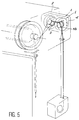
- la figure 5 est une vue en perspective d'un châssis de volet roulant pourvu du dispositif selon l'invention.
- Selon un mode préféré de réalisation du dispositif de guidage selon l'invention, il comporte principalement une embase 1 pourvue de pattes, obtenues par pliage ou emboutissage d'un feuillard métallique, ou par moulage d'une matière plastique. Cette embase 1 s'étend globalement sous la forme d'un U et elle est munie sur chacune de ces parois 3 latérales d'un orifice 4 qui est préférentiellement comblé par un palier 5. Ce palier est emprisonné en translation dans le logement, mais peut exécuter un mouvement de rotation avant/arrière, selon une amplitude de 360°.
- Selon un autre mode de réalisation, le dispositif de guidage est élaboré à partir d'un montage d'une pluralité de pattes 2 dont l'orientation des faces latérales est non parallèle et s'étend notamment en L, en T, en H, les paliers 5 étant disposés éventuellement sur chacune des faces 3 et selon des axes de rotation sécants.
- Suivant les applications visées, il est possible d'inclure dans le chemin de roulement du palier 5, des butées 6 radiales qui limiteront, entre deux positions angulaires, l'amplitude du mouvement de rotation.
- On prévoit également d'interposer dans la zone de roulement entre le palier 5 et la patte 2, une cage 7 pourvue d'organes de roulement à rouleaux ou à billes. Avantageusement, il est préférable, pour diminuer les coûts de fabrication et l'encombrement des pièces, de choisir comme matériau de construction de l'une des pièces en mouvement relatif (palier, logement dans la patte), une matière notamment plastique ("Teflon", "Delrin", ou de la famille chimique des polyoléfines...) qui favorise le glissement.
- Selon un autre mode de réalisation de l'invention, le dispositif de guidage comporte une liaison pivot 8 entre le palier 5 et la patte 2, cette liaison pouvant éventuellement être limitée en amplitude par des butées 6, le guidage du palier dans son logement est assuré de manière similaire, par une cage usinée dans le siège ou rapportée.
- Quel que soit le mode de réalisation, pivot ou rotation simple, le palier 5 dispose d'une ouverture 9, notamment de section droite rectangulaire ou carrée, destinée à recevoir un organe de roulement 10. L'organe de roulement 10 est conformé en rouleau de profil cylindrique ou tronconique, suivant l'orientation à communiquer à la sangle, et dispose en son centre d'un axe de rotation 11 longitudinal qui coopère au droit de deux faces latérales de ladite ouverture 9 du palier 5.
- On prévoit également de munir l'organe de roulement 10 à chaque extrémité d'un épaulement 12 qui limite le déplacement longitudinal de la sangle sur l'organe de roulement et évite qu'elle ne vienne "brouter" contre les parois latérales de l'ouverture, garantissant ainsi un rendement optimum au guidage.
- Selon une autre caractéristique avantageuse de l'invention, l'axe de rotation de l'organe de roulement 11 est décalé longitudinalement par rapport à l'axe médian 13 de l'ouverture, afin que l'organe de roulement soit placé dans une position asymétrique dans son logement, généralement l'axe de rotation se trouve en-dessous de l'axe médian, pour favoriser son autopositionnement quelle que soit l'orientation de la sangle.
- L'invention décrite ci-dessus offre de multiples avantages, en particulier elle permet un montage de l'enrouleur de sangle en dehors de la zone d'ouverture de l'ouvrant ou dans une zone décalée par rapport aux huisseries de la baie ainsi équipée.
- Il demeure bien entendu que la présente invention n'est pas limitée aux exemples de réalisation décrits et représentés ci-dessus, mais qu'elle en englobe toutes les variantes.
Claims (9)
Applications Claiming Priority (2)
| Application Number | Priority Date | Filing Date | Title |
|---|---|---|---|
| FR9407388A FR2721302B1 (fr) | 1994-06-16 | 1994-06-16 | Dispositif de déport de sangle. |
| FR9407388 | 1994-06-16 |
Publications (2)
| Publication Number | Publication Date |
|---|---|
| EP0687796A1 true EP0687796A1 (fr) | 1995-12-20 |
| EP0687796B1 EP0687796B1 (fr) | 1998-09-09 |
Family
ID=9464293
Family Applications (1)
| Application Number | Title | Priority Date | Filing Date |
|---|---|---|---|
| EP19950401389 Expired - Lifetime EP0687796B1 (fr) | 1994-06-16 | 1995-06-14 | Dispositif de déport de sangle |
Country Status (4)
| Country | Link |
|---|---|
| EP (1) | EP0687796B1 (fr) |
| DE (2) | DE69504578T2 (fr) |
| ES (1) | ES2081794T3 (fr) |
| FR (1) | FR2721302B1 (fr) |
Families Citing this family (2)
| Publication number | Priority date | Publication date | Assignee | Title |
|---|---|---|---|---|
| DE10250794B4 (de) * | 2002-10-30 | 2019-12-05 | Konrad Wetzstein | Gurtführungsvorrichtung |
| KR101957027B1 (ko) * | 2016-07-06 | 2019-03-11 | 데 요 컴퍼니 리미티드 | 창문 가리개 |
Citations (2)
| Publication number | Priority date | Publication date | Assignee | Title |
|---|---|---|---|---|
| DE8610444U1 (de) * | 1986-04-17 | 1986-05-28 | Karl Rau GmbH & Co, 7340 Geislingen | Gurtführungseinrichtung für Rolladen-Vorbauelemente |
| FR2624908A1 (fr) * | 1987-12-17 | 1989-06-23 | Heimerdinger Maurice | Deviateur de sangle pour volet roulant |
-
1994
- 1994-06-16 FR FR9407388A patent/FR2721302B1/fr not_active Expired - Fee Related
-
1995
- 1995-06-14 ES ES95401389T patent/ES2081794T3/es not_active Expired - Lifetime
- 1995-06-14 DE DE1995604578 patent/DE69504578T2/de not_active Expired - Lifetime
- 1995-06-14 EP EP19950401389 patent/EP0687796B1/fr not_active Expired - Lifetime
- 1995-06-14 DE DE1995401389 patent/DE687796T1/de active Pending
Patent Citations (2)
| Publication number | Priority date | Publication date | Assignee | Title |
|---|---|---|---|---|
| DE8610444U1 (de) * | 1986-04-17 | 1986-05-28 | Karl Rau GmbH & Co, 7340 Geislingen | Gurtführungseinrichtung für Rolladen-Vorbauelemente |
| FR2624908A1 (fr) * | 1987-12-17 | 1989-06-23 | Heimerdinger Maurice | Deviateur de sangle pour volet roulant |
Also Published As
| Publication number | Publication date |
|---|---|
| DE69504578T2 (de) | 1999-02-04 |
| FR2721302A1 (fr) | 1995-12-22 |
| ES2081794T3 (es) | 1998-11-01 |
| EP0687796B1 (fr) | 1998-09-09 |
| DE69504578D1 (de) | 1998-10-15 |
| DE687796T1 (de) | 1996-10-10 |
| FR2721302B1 (fr) | 1996-09-06 |
| ES2081794T1 (es) | 1996-03-16 |
Similar Documents
| Publication | Publication Date | Title |
|---|---|---|
| EP2042217B1 (fr) | Dispositif antichute destiné à coopérer avec un support d'assurage rigide | |
| EP0187729A1 (fr) | Vanne à obturateur sphérique | |
| FR3080422A1 (fr) | Dispositif de poulie pour galet tendeur ou enrouleur | |
| EP1080311B1 (fr) | Cable pour commande a distance | |
| EP0703395B1 (fr) | Système d'immobilisation axial d'un organe allongé | |
| EP2499712B1 (fr) | Support pour maintenir en position des objets allongés par rapport à une structure | |
| FR2482691A1 (fr) | Galet tendeur pour courroies | |
| EP0687796A1 (fr) | Dispositif de déport de sangle | |
| FR2747444A1 (fr) | Montage de roue libre | |
| FR2563176A1 (fr) | Dispositif de montage notamment de l'articulation du bras tendeur guide-chaine des changements de vitesse pour bicyclettes et vehicules similaires | |
| FR2541393A1 (fr) | Dispositif de serrage automatique de paliers obliques serres l'un vis-a-vis de l'autre par paires d'un ensemble de paliers lisses ou a roulement pour un arbre entraine | |
| EP3379105B1 (fr) | Élément d'engrenage à rouleaux | |
| FR2839125A1 (fr) | Mecanisme d'embrayage a cones | |
| FR2787152A1 (fr) | Dispositif a doigt pour le blocage d'une piece par rapport a une autre | |
| EP1590273A1 (fr) | Palette pour cha ne de convoyeur-------------------------- | |
| EP1700988B1 (fr) | Dispositif d'ouverture et de fermeture d'une structure mobile | |
| FR2867534A1 (fr) | Mecanisme d'embrayage a cones | |
| EP1757828B1 (fr) | Dispositif d'arrêt de système de roulement et procédé de montage | |
| FR2891603A1 (fr) | Poulie pour bateaux a voile de haute performance. | |
| FR2861763A1 (fr) | Dispositif d'assemblage d'elements de charpente et ensemble comportant un tel dispositif d'assemblage. | |
| FR3069293A1 (fr) | Palier a roulement | |
| FR2817305A1 (fr) | Articulation pour commande a billes | |
| FR2824614A1 (fr) | Dispositif de protection pour le passage d'une corde, d'un tuyau ou similaire | |
| FR2767165A1 (fr) | Perfectionnement pour dispositif de transmission de mouvement rotatif de type joint homocinetique et dispositif de commande d'un organe mobile muni de ce dispositif | |
| FR2577876A1 (fr) | Tete de support d'une poulie dans une installation de transport par cable |
Legal Events
| Date | Code | Title | Description |
|---|---|---|---|
| PUAI | Public reference made under article 153(3) epc to a published international application that has entered the european phase |
Free format text: ORIGINAL CODE: 0009012 |
|
| AK | Designated contracting states |
Kind code of ref document: A1 Designated state(s): BE DE ES IT NL |
|
| ITCL | It: translation for ep claims filed |
Representative=s name: BARZANO' E ZANARDO MILANO S.P.A. |
|
| 17P | Request for examination filed |
Effective date: 19960105 |
|
| REG | Reference to a national code |
Ref country code: ES Ref legal event code: BA2A Ref document number: 2081794 Country of ref document: ES Kind code of ref document: T1 |
|
| TCNL | Nl: translation of patent claims filed | ||
| DET | De: translation of patent claims | ||
| 17Q | First examination report despatched |
Effective date: 19970304 |
|
| GRAG | Despatch of communication of intention to grant |
Free format text: ORIGINAL CODE: EPIDOS AGRA |
|
| GRAG | Despatch of communication of intention to grant |
Free format text: ORIGINAL CODE: EPIDOS AGRA |
|
| GRAH | Despatch of communication of intention to grant a patent |
Free format text: ORIGINAL CODE: EPIDOS IGRA |
|
| GRAH | Despatch of communication of intention to grant a patent |
Free format text: ORIGINAL CODE: EPIDOS IGRA |
|
| GRAA | (expected) grant |
Free format text: ORIGINAL CODE: 0009210 |
|
| ITF | It: translation for a ep patent filed | ||
| AK | Designated contracting states |
Kind code of ref document: B1 Designated state(s): BE DE ES IT NL |
|
| PG25 | Lapsed in a contracting state [announced via postgrant information from national office to epo] |
Ref country code: NL Free format text: LAPSE BECAUSE OF FAILURE TO SUBMIT A TRANSLATION OF THE DESCRIPTION OR TO PAY THE FEE WITHIN THE PRESCRIBED TIME-LIMIT Effective date: 19980909 |
|
| RAP1 | Party data changed (applicant data changed or rights of an application transferred) |
Owner name: ZURFLUH-FELLER S.A. |
|
| REF | Corresponds to: |
Ref document number: 69504578 Country of ref document: DE Date of ref document: 19981015 |
|
| REG | Reference to a national code |
Ref country code: ES Ref legal event code: FG2A Ref document number: 2081794 Country of ref document: ES Kind code of ref document: T3 |
|
| NLV1 | Nl: lapsed or annulled due to failure to fulfill the requirements of art. 29p and 29m of the patents act | ||
| PLBE | No opposition filed within time limit |
Free format text: ORIGINAL CODE: 0009261 |
|
| STAA | Information on the status of an ep patent application or granted ep patent |
Free format text: STATUS: NO OPPOSITION FILED WITHIN TIME LIMIT |
|
| 26N | No opposition filed | ||
| PGFP | Annual fee paid to national office [announced via postgrant information from national office to epo] |
Ref country code: ES Payment date: 20110624 Year of fee payment: 17 |
|
| PGFP | Annual fee paid to national office [announced via postgrant information from national office to epo] |
Ref country code: BE Payment date: 20110614 Year of fee payment: 17 Ref country code: DE Payment date: 20110622 Year of fee payment: 17 |
|
| PGFP | Annual fee paid to national office [announced via postgrant information from national office to epo] |
Ref country code: IT Payment date: 20110625 Year of fee payment: 17 |
|
| BERE | Be: lapsed |
Owner name: S.A. *ZURFLUH-FELLER Effective date: 20120630 |
|
| PG25 | Lapsed in a contracting state [announced via postgrant information from national office to epo] |
Ref country code: IT Free format text: LAPSE BECAUSE OF NON-PAYMENT OF DUE FEES Effective date: 20120614 |
|
| REG | Reference to a national code |
Ref country code: DE Ref legal event code: R119 Ref document number: 69504578 Country of ref document: DE Effective date: 20130101 |
|
| PG25 | Lapsed in a contracting state [announced via postgrant information from national office to epo] |
Ref country code: DE Free format text: LAPSE BECAUSE OF NON-PAYMENT OF DUE FEES Effective date: 20130101 Ref country code: BE Free format text: LAPSE BECAUSE OF NON-PAYMENT OF DUE FEES Effective date: 20120630 |
|
| REG | Reference to a national code |
Ref country code: ES Ref legal event code: FD2A Effective date: 20131022 |
|
| PG25 | Lapsed in a contracting state [announced via postgrant information from national office to epo] |
Ref country code: ES Free format text: LAPSE BECAUSE OF NON-PAYMENT OF DUE FEES Effective date: 20120615 |