EP0687853A2 - Stufenweise Verbrennung zur Reduktion von Stickstoffoxiden - Google Patents
Stufenweise Verbrennung zur Reduktion von Stickstoffoxiden Download PDFInfo
- Publication number
- EP0687853A2 EP0687853A2 EP95109042A EP95109042A EP0687853A2 EP 0687853 A2 EP0687853 A2 EP 0687853A2 EP 95109042 A EP95109042 A EP 95109042A EP 95109042 A EP95109042 A EP 95109042A EP 0687853 A2 EP0687853 A2 EP 0687853A2
- Authority
- EP
- European Patent Office
- Prior art keywords
- stream
- oxidant
- fuel
- liquid fuel
- velocity
- Prior art date
- Legal status (The legal status is an assumption and is not a legal conclusion. Google has not performed a legal analysis and makes no representation as to the accuracy of the status listed.)
- Granted
Links
Images


Classifications
-
- F—MECHANICAL ENGINEERING; LIGHTING; HEATING; WEAPONS; BLASTING
- F23—COMBUSTION APPARATUS; COMBUSTION PROCESSES
- F23C—METHODS OR APPARATUS FOR COMBUSTION USING FLUID FUEL OR SOLID FUEL SUSPENDED IN A CARRIER GAS OR AIR
- F23C1/00—Combustion apparatus specially adapted for combustion of two or more kinds of fuel simultaneously or alternately, at least one kind of fuel being either a fluid fuel or a solid fuel suspended in a carrier gas or air
-
- F—MECHANICAL ENGINEERING; LIGHTING; HEATING; WEAPONS; BLASTING
- F23—COMBUSTION APPARATUS; COMBUSTION PROCESSES
- F23D—BURNERS
- F23D11/00—Burners using a direct spraying action of liquid droplets or vaporised liquid into the combustion space
- F23D11/10—Burners using a direct spraying action of liquid droplets or vaporised liquid into the combustion space the spraying being induced by a gaseous medium, e.g. water vapour
-
- F—MECHANICAL ENGINEERING; LIGHTING; HEATING; WEAPONS; BLASTING
- F23—COMBUSTION APPARATUS; COMBUSTION PROCESSES
- F23C—METHODS OR APPARATUS FOR COMBUSTION USING FLUID FUEL OR SOLID FUEL SUSPENDED IN A CARRIER GAS OR AIR
- F23C6/00—Combustion apparatus characterised by the combination of two or more combustion chambers or combustion zones, e.g. for staged combustion
- F23C6/04—Combustion apparatus characterised by the combination of two or more combustion chambers or combustion zones, e.g. for staged combustion in series connection
- F23C6/045—Combustion apparatus characterised by the combination of two or more combustion chambers or combustion zones, e.g. for staged combustion in series connection with staged combustion in a single enclosure
-
- F—MECHANICAL ENGINEERING; LIGHTING; HEATING; WEAPONS; BLASTING
- F23—COMBUSTION APPARATUS; COMBUSTION PROCESSES
- F23L—SUPPLYING AIR OR NON-COMBUSTIBLE LIQUIDS OR GASES TO COMBUSTION APPARATUS IN GENERAL ; VALVES OR DAMPERS SPECIALLY ADAPTED FOR CONTROLLING AIR SUPPLY OR DRAUGHT IN COMBUSTION APPARATUS; INDUCING DRAUGHT IN COMBUSTION APPARATUS; TOPS FOR CHIMNEYS OR VENTILATING SHAFTS; TERMINALS FOR FLUES
- F23L7/00—Supplying non-combustible liquids or gases, other than air, to the fire, e.g. oxygen, steam
- F23L7/007—Supplying oxygen or oxygen-enriched air
-
- F—MECHANICAL ENGINEERING; LIGHTING; HEATING; WEAPONS; BLASTING
- F23—COMBUSTION APPARATUS; COMBUSTION PROCESSES
- F23D—BURNERS
- F23D2900/00—Special features of, or arrangements for burners using fluid fuels or solid fuels suspended in a carrier gas
- F23D2900/00006—Liquid fuel burners using pure oxygen or oxygen-enriched air as oxidant
-
- Y—GENERAL TAGGING OF NEW TECHNOLOGICAL DEVELOPMENTS; GENERAL TAGGING OF CROSS-SECTIONAL TECHNOLOGIES SPANNING OVER SEVERAL SECTIONS OF THE IPC; TECHNICAL SUBJECTS COVERED BY FORMER USPC CROSS-REFERENCE ART COLLECTIONS [XRACs] AND DIGESTS
- Y02—TECHNOLOGIES OR APPLICATIONS FOR MITIGATION OR ADAPTATION AGAINST CLIMATE CHANGE
- Y02E—REDUCTION OF GREENHOUSE GAS [GHG] EMISSIONS, RELATED TO ENERGY GENERATION, TRANSMISSION OR DISTRIBUTION
- Y02E20/00—Combustion technologies with mitigation potential
- Y02E20/34—Indirect CO2mitigation, i.e. by acting on non CO2directly related matters of the process, e.g. pre-heating or heat recovery
Definitions
- the present invention relates generally to fluid fuel combustion and particularly to liquid fuel combustion useful for minimizing the formation of nitrogen oxides.
- Nitrogen oxides are generated in a significant amount in many combustion processes. Since nitrogen oxides are known pollutants, it is desirable to reduce their generation during the combustion. To reduce nitrogen oxides generation, an oxygen enriched air or technically pure oxygen has been used in lieu of air as the oxidant to reduce the amount of nitrogen introduced per an equivalent amount of oxygen into a combustion zone. However, the use of an oxygen enriched air or technically pure oxygen as the oxidant causes the combustion processes to be carried out at high temperature. High temperature combustion kinetically favors the formation of nitrogen oxides and adversely affects the structural life of burners, particularly non-water cooled burners.
- U.S. Patent Nos. 5,076,779 and 5,242,296 disclose combustion methods wherein the formation of nitrogen oxides is suppressed.
- the combustion methods include diluting an oxidant stream with furnace gases in an oxidant mixing zone to form a diluted stream and then combusting fuel in the presence of the diluted stream in a reaction zone to avoid the conditions which favor nitrogen oxide formation.
- the fuel may be initially subject to partial combustion in the presence of a substoichiometric amount of oxidant before it is completely combusted in the presence of the diluted stream.
- a process for combusting fluid fuel with reduced nitrogen oxides generation comprising:
- a process for combusting liquid fuel with reduced nitrogen oxides generation comprising:
- ambient gas means gases within a combustion zone, i.e., a furnace.
- partially combusted products means products of complete and incomplete combustion, including but not limited to CO2, CO, H2O, H2, hydrocarbon and unburned fuel.
- Figures 1 and 2 are cross-sectional views of various configurations relating to the introduction of primary oxidant, secondary oxidant and fuel, which are embodiments of the invention.
- Figure 3 is a cross-sectional view of an liquid fuel atomizing apparatus, which is another embodiment of the invention.
- Figures 4 is a cross-sectional view of liquid fuel burners having the atomizer of Figure 3, which is yet another embodiment of the invention.
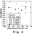
- Figures 5-6 are graphical representations illustrating the importance of using particular volume ratios of secondary oxidant stream to primary oxidant, which is an additional embodiment of the invention.
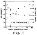
- Figures 7-8 are graphical representations illustrating the importance of ejecting secondary oxidant at particular velocities, which is a further embodiment of the invention.
- fluid fuel and primary oxidant are ejected from one or more burners (3) having at least one fuel passageway (5) and at least one primary oxidant passageway (7).
- the burners (3) may comprise a nozzle (9) and an enclosure (11) concentrically surrounding at least a portion of the length of a nozzle(9).
- the annular passageway formed between the exterior surface of the nozzle (9) and the interior surface of the enclosure (11) represents the primary oxidant passageway (7) while the passageway of the nozzle (9) represents the fuel passageway (5).
- At least one atomizing fluid passageway (13) is provided, when liquid fuel is employed.
- the desired atomizing fluid passageway (13) is appropriately designed and properly located to produce at least one liquid fuel stream in the form of a spreading spray having an outer periphery angle of less than 15°, preferably less than 10°, measured from the axis of said at least one liquid fuel stream.
- the atomizing fluid passageway (13) may be provided in the form of an intermediate annular passageway by concentrically surrounding at least a portion of the length of the nozzle (9) with an intermediate enclosure (15)(e.g., a fluid conduit placed between the nozzle and the enclosure (11)).
- the nozzle (9) useful for ejecting a liquid fuel spray having the desired narrow outer periphery angle has interior and exterior surfaces, with the interior surface defining the fuel passageway (5) which terminates with a fuel port (17).
- the fuel passageway (5) may comprise at least two lengths.
- the first length (5a) has a relatively large cross-sectional area or diameter while the second length (5b), which communicates with the first length (5a), has a cross-sectional area which decreases in the direction of the fuel port (17) (a radially decreasing taper), preferably in the form of a cone.
- the fuel port (17) has an inlet (19) for receiving fuel from the fuel passageway (5) and an outlet (21) for discharging fuel.
- the inlet (19) of the fuel port (17) is normally located at the end of the second length (5b) and has a cross-sectional area or diameter equal to or smaller than the cross-sectional area or diameter of the end opening of the second length (5b).
- the fuel port (17) may comprise at least three sections, with the first section (17a) having a diameter or a cross-sectional area equal to or smaller than the cross-sectional area or diameter at the end of the second length (5b) of the fuel passageway (5), the second section (17b) having a slightly decreasing cross-sectional area or diameter in the direction of the outlet (21) and the third section (17c) having a cross-sectional area or a diameter smaller than the cross-sectional area or diameter of the first section (17a).
- the fuel passageway (5) has a cross-sectional area or a diameter greater than the cross-sectional area or the diameter of the fuel port (17).
- the intermediate enclosure (15) useful for forming the atomizing fluid passageway (13) capable of promoting the formation of a fuel spray having the desired outer periphery angle has interior and exterior surfaces and concentrically surrounds at least a portion of the nozzle (9). Between the interior surface of the enclosure (15) and the exterior surface of the nozzle (9), the atomizing fluid passageway (13), e.g., an annular passageway, and an atomizing fluid port (23), e.g., an annular atomizing fluid port.
- the annular atomizing fluid passageway (13) terminates with the annular atomizing fluid port (23) having inlet and outlet openings (25 and 27) for receiving and discharging atomizing fluid from the annular passageway (13).
- the annular atomizing fluid passageway (13) normally has a cross-sectional area or a diameter greater or larger than the cross-sectional area or the diameter of the annular atomizing fluid port (23). At least a portion of the interior surface of the intermediate enclosure (15) and at least a portion of the exterior surface of the nozzle (9) defining the annular atomizing fluid port (13) are in the form of a cone having a diameter decreasing toward the outlet opening at an angle (A) in the range of about 5° to about 30°, preferably about 12° to about 18°, measured from the longitudinal axis (C) of the nozzle (9).
- additional enclosures are needed to form additional passageways (e.g., additional annular passageways) for injecting different fuel, such as a fluid containing solid fuel particles or gaseous fuel, and additional primary oxidant.
- the tip of at least one burners (3) may be recessed from at least one internal opening (28) of at least one refractory port (29) defined in at least one furnace wall (31) so that they may be used as non-water cooled burners.
- Each refractory port (29) has the internal opening (28) which faces a combustion zone (33) formed within the furnace wall (31).
- the diameter of the internal opening (28) is in the range of about 0.25 to about 10 inches. It was discovered that, by recessing the tip of each burner (3) from the internal opening (28) of the refractory port (29) by a distance of at least the diameter of the refractory port internal opening (28), each burner (3) can be employed without employing water cooling means. This recessed distance reduces the burner tip temperature.
- the burners (3) may be made with any materials which are compatible to combustion processes. Such materials include, among other things, stainless steel, metals, ceramics and plastics.
- the fluid fuel employed may be liquid fuel, gaseous fuel, fluid containing solid fuel or mixtures thereof.
- the fuel such as oils or coal, may contain chemically bound nitrogen.
- chemically bound nitrogen means nitrogen atom which is chemically attached to chemical compounds (excluding molecular nitrogen). Some of the chemical compounds having chemically bound nitrogen includes, among other things, amines, amides and heterocyclic compounds having nitrogen. If the liquid fuel employed has a high viscosity, it may be preheated before being delivered into the fuel passageway (5).
- the velocity of the fluid fuel is preferably greater than the velocity of the primary oxidant to promote stable partial combustion of the fluid fuel.
- atomizing fluid is used to disperse the liquid fuel for efficient and effective combustion.
- the preferred atomization technique is such that the atomizing fluid causes the resulting atomized liquid fuel stream to have the desired narrow outer periphery spray angle consistently even when the liquid fuel is ejected at a low velocity, e.g. a velocity less than 50 feet per second.
- the preferred atomization technique involves ejecting the atomizing fluid at a velocity of about 0.5 to 1.2 Mach and converging the liquid fuel at a converging angle (A) in the range of about 5° to about 30°, preferably about 12° to about 18°, measured from the longitudinal axis (C) of the nozzle (9).
- the atomizing fluid ejected from the annular atomizing fluid port (23) subsequently entrains at least a portion of the primary oxidant within the liquid fuel stream, thus causing partial combustion of the liquid fuel.
- Other atomization techniques may be employed as long as the desired narrow outer periphery spray angle can be obtained and as long as at least a portion of the primary oxidant is entrained within the liquid fuel stream. The obtention of this desired narrow outer periphery spray angle, not only promotes the use of a non-water cooled oil-fuel burner, but also enhances the effective and efficient combustion of the liquid fuel with reduced generation of nitrogen oxides.
- controlling or adjusting the rate of the atomizing fluid ejected to maintain the mass ratio of the atomizing fluid to the liquid fuel in the range of about 0.3 to about 0.7, preferably about 0.4 to 0.7 further promotes the reduction of the nitrogen oxides emission levels.
- the atomizing fluid employed can be any gaseous substance, including but not limited to steam, carbon dioxides, argon, nitrogen, air, oxygen enriched air and pure oxygen.
- the atomizing gas which does not contain nitrogen is generally preferred.
- the primary oxidant ejected from the primary oxidant passageway (7) shrouds and reacts with the fluid fuel.
- the primary oxidant ejected contains a substoichiometric amount of oxygen for reacting the fluid fuel, thus causing partial combustion of the fluid fuel.
- the desired substoichiometric amount of oxygen is about 10 to 30 percent of a stoichiometric amount of oxygen for reacting the fluid fuel stream.
- the velocity of the primary oxidant is normally maintained less than 200 feet per second, preferably less than 100 feet per second, to promote the stable partial combustion and reduce the formation of nitrogen oxides.
- the primary oxidant employed may be air, oxygen enriched air or technically pure oxygen.
- the desired primary oxidant contains an oxygen concentration of greater than 30 percent by volume.
- additional primary oxidant and fuel may be introduced through additional passageways, e.g., outer annular passageways, within the burners (3).
- additional primary oxidant and fuel e.g., different fuel
- the burners (3) for example, can be used as a dual fuel burner.
- a secondary oxidant stream is ejected from at least one lance (35).
- the lance (35) is placed within at least one second refractory port (37) of the furnace wall (31).
- the refractory port (37) has an internal opening (36) which faces the combustion zone (33).
- the tip of the lance (35) may be recessed from the internal opening (36) of the refractory port (37) by a distance equal to at least the diameter of the internal opening (36) of the refractory port (37). If the tip of lance (35) is made with ceramic materials, it need not be recessed. This lance design or recess allows the lance (35) to be operated without water cooling, thus avoiding corrosion associated with water cooling.
- the position of the lance (35) causes the secondary oxidant stream to be ejected from a point spaced from, angled away from, opposite to and/or adjacent to where the primary oxidant and fuel streams are being ejected.
- the spacing distance and/or the ejection angle is such that the ejected secondary oxidant stream entrains a large volume of ambient gas, that is, the gas within the combustion zone or furnace, before the secondary stream reacts with the partially combusted products.
- the point at which the secondary oxidant is ejected should be at least 3 inches spaced away from a point at which the fuel and primary oxidant streams are ejected.
- the lance (35) is located at least one wall opposite and/or adjacent to where the burners (3) is located, a point at which the partially combusted products and the secondary oxidant are intersected should be sufficiently far from a point where the secondary oxidant is ejected to cause the formation of the desired diluted stream before the secondary oxidant stream is mixed with the partially combusted products.
- the desired diluted stream has an oxygen concentration of about 1 to about 30 percent by volume, preferably about 2 to about 25 percent by volume.
- the desired dilute stream is formed by establishing an ambient gas circulation pattern with the secondary oxidant stream whereby the secondary oxidant stream entrains the ambient gas before it is used for combusting the partially combusted products.
- the ambient gas normally contains an oxygen concentration of about 0.5 to about 15 percent.
- the amount of the secondary oxidant introduced is regulated or adjusted based on the amount of the primary oxidant introduced to further reduce the formation of nitrogen oxides.
- Figures 5-6 illustrates a plot of NOx (the nitrogen oxides emission level) versus the secondary oxidant injection velocity using different ratios of the secondary oxidant to primary oxidant. The plot suggests that the mass of nitrogen oxides generated is decreased with the increased volume ratio of the secondary oxidant to the primary oxidant.
- the desired volume ratio of the primary oxidant to the secondary is greater than 1.5:1, preferably greater than or equal to 2.4:1, more preferably greater than 3:1 but less than 20:1.
- Figures 7-8 show a plot of NOx (the nitrogen oxides emission level) versus secondary oxidant back pressure and secondary oxidant injection velocity. The plot indicates that the mass of nitrogen oxides generated decreases with increasing the secondary oxidant injection velocity or the secondary oxidant back pressure.
- the desired velocity of the secondary oxidant is greater than 250 feet per second, preferably greater than 300 feet per second, more preferably greater than 400 feet per second.
- the secondary oxidant employed can be air, oxygen enriched air or technically pure oxygen. The desired secondary oxidant, however, contains an oxygen concentration of greater than 30 percent by volume.
- the secondary oxidant ejected at a high velocity from the desired locations as indicated above establishes ambient gas circulation pattern whereby the ambient gas and partially combusted products resulting from combusting fuel with the primary oxidant are entrained into the secondary oxidant stream due to the jet aspiration effects of the secondary oxidant stream. Since the velocity of the secondary oxidant stream is high and is ejected from a point sufficiently away from the fuel and primary oxidant streams, mixing of the secondary oxidant with the fuel and primary oxidant is delayed. This delay allows the secondary oxidant to be mixed with the ambient gas initially to form the desired diluted stream while forming partially combusted products through partial combustion of the fuel with the primary oxidant. The resulting diluted stream then entrains and combusts the partially combusted products.
- the oil was pumped at 140°F and the temperature at the burner inlet was kept at 180°F in order to keep the oil viscosity at 16 cSt (centistokes).
- the burner was fired at a firing rate of 1 MM Btu/h.
- Nitrogen was injected through three points in the furnace side wall in order to simulate air infiltration since this problem occurs in industrial furnaces.
- the furnace refractory wall average temperature was kept at 2800 °F during the NOx measurements.
- the NOx results are expressed based on NO measured by a chemiluminescent analyzer and expressed as lb (pound) of NO2 per million BTU of fuel fired.
- the tests were carried out with the burner shown in Figure 4.
- the burner was placed within refractory port defined in the furnace wall such that the tip of the burner was recessed from the internal opening of the port by about 4 inches (twice the diameter of the internal opening).
- An oxygen lance was placed within another refractory port defined in the furnace wall such that the tip of the lance is recessed from the internal opening of the port by about 2 inches (a distance equal to the diameter of the internal opening of another refractory port). Both the burner and the lance were installed parallel to each other and were about 6 inches apart from one another. While the lance was used to eject secondary oxidant, the burner was used to eject oil, atomizing fluid and primary oxidant to partially combust the oil.
- FIGs 7-8 the effect of the secondary oxidant injection velocity on the nitrogen oxides emission level is illustrated.
- the amount of the primary oxidant injected was such that oxygen introduced through the burner constitutes about 30% and 40% respectively for Figures 7 and 8 based on the total oxygen introduced.
- the atomizing fluid employed is steam for both Figures 7 and 8. According to the plots in Figures 7 and 8, increasing the velocity of the secondary oxidant decreases the nitrogen oxides emission level.
- the nitrogen oxide emission level is significantly reduced.
- the reduction of the nitrogen oxide level in the context of liquid fuel combustion is especially noteworthy because the reduction of the nitrogen oxide emission level provided by the invention using a liquid fuel stream having a very narrow spray angle would not have been contemplated by those skilled in the art due to the complexities associated with liquid fuel atomization and combustion.
- being able to use the liquid fuel stream having a very narrow spray angle with reduced nitrogen oxides generation allows the burner to be used without water cooling and without causing fouling and corrosion for a long period.
Landscapes
- Engineering & Computer Science (AREA)
- Chemical & Material Sciences (AREA)
- Combustion & Propulsion (AREA)
- Mechanical Engineering (AREA)
- General Engineering & Computer Science (AREA)
- Nozzles For Spraying Of Liquid Fuel (AREA)
- Spray-Type Burners (AREA)
- Air Supply (AREA)
Applications Claiming Priority (2)
| Application Number | Priority Date | Filing Date | Title |
|---|---|---|---|
| US259110 | 1994-06-13 | ||
| US08/259,110 US5601425A (en) | 1994-06-13 | 1994-06-13 | Staged combustion for reducing nitrogen oxides |
Publications (3)
| Publication Number | Publication Date |
|---|---|
| EP0687853A2 true EP0687853A2 (de) | 1995-12-20 |
| EP0687853A3 EP0687853A3 (de) | 1997-03-05 |
| EP0687853B1 EP0687853B1 (de) | 2000-09-27 |
Family
ID=22983576
Family Applications (1)
| Application Number | Title | Priority Date | Filing Date |
|---|---|---|---|
| EP95109042A Revoked EP0687853B1 (de) | 1994-06-13 | 1995-06-12 | Stufenweise Verbrennung zur Reduktion von Stickstoffoxiden |
Country Status (10)
| Country | Link |
|---|---|
| US (1) | US5601425A (de) |
| EP (1) | EP0687853B1 (de) |
| JP (1) | JP3017048B2 (de) |
| KR (1) | KR100234573B1 (de) |
| CN (1) | CN1171032C (de) |
| BR (1) | BR9502780A (de) |
| CA (1) | CA2151540C (de) |
| DE (1) | DE69518952T2 (de) |
| ES (1) | ES2151006T3 (de) |
| PT (1) | PT687853E (de) |
Cited By (7)
| Publication number | Priority date | Publication date | Assignee | Title |
|---|---|---|---|---|
| EP0877202A3 (de) * | 1997-05-07 | 1999-06-23 | The BOC Group plc | Drallbrenner für Sauerstoff und Heizöl |
| FR2853953A1 (fr) * | 2003-04-18 | 2004-10-22 | Air Liquide | Procede de combustion etagee d'un combustible liquide et d'un oxydant dans un four |
| EP1531303A1 (de) * | 2003-11-14 | 2005-05-18 | Air Products And Chemicals, Inc. | Verbesserte gestuffte Brennstoffversorgung für Betrieb mit niedrigem NOx-Ausstoss |
| WO2009038849A3 (en) * | 2007-06-29 | 2009-06-04 | Praxair Technology Inc | Low velocity staged combustion for furnace atmosphere control |
| WO2012092069A3 (en) * | 2010-12-30 | 2013-10-24 | L'air Liquide Societe Anonyme Pour L'etude Et L'exploitation Des Procedes Georges Claude | Distributed combustion process and burner |
| CN103429957A (zh) * | 2011-01-26 | 2013-12-04 | 大阳日酸株式会社 | 燃烧器的燃烧方法 |
| WO2015007252A1 (en) | 2013-07-15 | 2015-01-22 | Flammatec, Spol. S R.O. | The way of gas combustion in industrial furnaces and burner for realization of this method |
Families Citing this family (42)
| Publication number | Priority date | Publication date | Assignee | Title |
|---|---|---|---|---|
| FR2722272B1 (fr) * | 1994-07-08 | 1996-08-23 | Air Liquide | Ensemble de combustion pour un four et procede de mise en oeuvre |
| US5755818A (en) * | 1995-06-13 | 1998-05-26 | Praxair Technology, Inc. | Staged combustion method |
| US5924858A (en) * | 1995-06-13 | 1999-07-20 | Praxair Technology, Inc. | Staged combustion method |
| EP0754912B1 (de) * | 1995-07-17 | 2004-06-09 | L'air Liquide, S.A. à Directoire et Conseil de Surveillance pour l'Etude et l'Exploitation des Procédés Georges Claude | Verbrennungsverfahren und Vorrichtung dafür mit getrennter Einspritzung von Brennstoff und Oxydationsmittel |
| US5984667A (en) * | 1995-07-17 | 1999-11-16 | American Air Liquide, Inc. | Combustion process and apparatus therefore containing separate injection of fuel and oxidant streams |
| US5727480A (en) * | 1996-04-17 | 1998-03-17 | Foster Wheeler International, Inc. | Over-fire air control system for a pulverized solid fuel furnace |
| US5992337A (en) * | 1997-09-26 | 1999-11-30 | Air Liquide America Corporation | Methods of improving productivity of black liquor recovery boilers |
| US6126438A (en) * | 1999-06-23 | 2000-10-03 | American Air Liquide | Preheated fuel and oxidant combustion burner |
| US6241510B1 (en) * | 2000-02-02 | 2001-06-05 | Praxair Technology, Inc. | System for providing proximate turbulent and coherent gas jets |
| US6699031B2 (en) | 2001-01-11 | 2004-03-02 | Praxair Technology, Inc. | NOx reduction in combustion with concentrated coal streams and oxygen injection |
| US6699030B2 (en) | 2001-01-11 | 2004-03-02 | Praxair Technology, Inc. | Combustion in a multiburner furnace with selective flow of oxygen |
| US6702569B2 (en) | 2001-01-11 | 2004-03-09 | Praxair Technology, Inc. | Enhancing SNCR-aided combustion with oxygen addition |
| US6699029B2 (en) | 2001-01-11 | 2004-03-02 | Praxair Technology, Inc. | Oxygen enhanced switching to combustion of lower rank fuels |
| US20020127505A1 (en) | 2001-01-11 | 2002-09-12 | Hisashi Kobayashi | Oxygen enhanced low nox combustion |
| US6685464B2 (en) * | 2001-03-28 | 2004-02-03 | L'Air Liquide - Societe Anonyme à Directoire et Conseil de Surveillance pour l'Etude et l'Exploitation des Procedes Georges Claude | High velocity injection of enriched oxygen gas having low amount of oxygen enrichment |
| FR2823290B1 (fr) | 2001-04-06 | 2006-08-18 | Air Liquide | Procede de combustion comportant des injections separees de combustible et d oxydant et ensemble bruleur pour la mise en oeuvre de ce procede |
| KR20020011351A (ko) * | 2001-08-30 | 2002-02-08 | 정욱진 | 황화수소를 포함한 악취가스의 저감을 위한생물탈취장치의 담체 및 그 제조방법 |
| US7225746B2 (en) * | 2002-05-15 | 2007-06-05 | Praxair Technology, Inc. | Low NOx combustion |
| ES2601702T3 (es) * | 2002-05-15 | 2017-02-16 | Praxair Technology, Inc. | Combustión con reducido carbono en la ceniza |
| CN1321290C (zh) * | 2002-12-24 | 2007-06-13 | 北京新宇阳科技有限公司 | 垃圾煤粉复合燃烧焚烧炉 |
| US20070048679A1 (en) * | 2003-01-29 | 2007-03-01 | Joshi Mahendra L | Fuel dilution for reducing NOx production |
| SE0501840L (sv) * | 2005-08-19 | 2007-02-20 | Aga Ab | Förfarande jämte för övervakning av en brännare |
| US20070231761A1 (en) * | 2006-04-03 | 2007-10-04 | Lee Rosen | Integration of oxy-fuel and air-fuel combustion |
| US20080096146A1 (en) * | 2006-10-24 | 2008-04-24 | Xianming Jimmy Li | Low NOx staged fuel injection burner for creating plug flow |
| US20100104990A1 (en) * | 2008-10-23 | 2010-04-29 | Sarmiento-Darkin Wladimir Y | Wide flame burner |
| US8727767B2 (en) * | 2009-01-16 | 2014-05-20 | Air Products And Chemicals, Inc. | Multi-mode combustion device and method for using the device |
| SE533967C2 (sv) * | 2009-03-20 | 2011-03-15 | Aga Ab | Förfarande för att homogenisera värmefördelningen samt minska mängden NOx vid förbränning |
| EP2440501A2 (de) * | 2009-06-12 | 2012-04-18 | Air Products and Chemicals, Inc. | Ofen und verfahren zur steuerung des oxidationszustands schmelzflüssiger materialien |
| JP5421728B2 (ja) * | 2009-10-23 | 2014-02-19 | 大阪瓦斯株式会社 | 溶解炉用の燃焼装置及び溶解炉 |
| CN103175202A (zh) * | 2011-12-20 | 2013-06-26 | 西安航天远征流体控制股份有限公司 | 非预混式开工烧嘴 |
| US20130180290A1 (en) | 2011-12-21 | 2013-07-18 | Hisashi Kobayashi | Controlling glassmelting furnace gas circulation |
| KR101400223B1 (ko) * | 2013-05-20 | 2014-05-27 | 주식회사 포스코 | 가열로 버너 |
| CA2915241A1 (en) | 2013-06-20 | 2014-12-24 | Praxair Technology, Inc. | Controlling glassmelting furnace operation |
| JP6446456B2 (ja) * | 2013-12-04 | 2018-12-26 | キング アブドゥーラ ユニバーシティ オブ サイエンス アンド テクノロジー | 燃焼および材料合成のための装置および方法 |
| CN105980774A (zh) * | 2013-12-04 | 2016-09-28 | 阿卜杜拉国王科技大学 | 用于燃烧的设备和方法 |
| EP2993397A1 (de) * | 2014-09-02 | 2016-03-09 | Linde Aktiengesellschaft | Brenner mit niedrigem NOx-Austoß |
| KR102093002B1 (ko) | 2015-04-16 | 2020-03-24 | 프랙스에어 테크놀로지, 인코포레이티드 | 노에서 연소를 수행하는 방법 |
| CN106090894B (zh) * | 2016-08-23 | 2019-10-29 | 翼特新能源科技(上海)有限公司 | 一种低NOx的全氧燃烧装置及其燃烧方法和应用 |
| JP6482513B2 (ja) | 2016-09-16 | 2019-03-13 | 大陽日酸株式会社 | バーナ |
| US10859260B2 (en) * | 2017-10-13 | 2020-12-08 | Praxair Technology, Inc. | Reduced fouling in staged combustion |
| MX2021013199A (es) | 2019-05-20 | 2021-12-10 | Praxair Technology Inc | Metodo para llevar a cabo la combustion en un horno con regeneracion termoquimica. |
| US20230184427A1 (en) | 2020-05-19 | 2023-06-15 | Flammatec, Spol. S R.O. | Method and burner of hydrogen combustion in industrial furnace, especially in a glass furnace or a furnace for metal melting, by means of a multi nozzle burner |
Citations (2)
| Publication number | Priority date | Publication date | Assignee | Title |
|---|---|---|---|---|
| US5076779A (en) | 1991-04-12 | 1991-12-31 | Union Carbide Industrial Gases Technology Corporation | Segregated zoning combustion |
| US5242296A (en) | 1992-12-08 | 1993-09-07 | Praxair Technology, Inc. | Hybrid oxidant combustion method |
Family Cites Families (22)
| Publication number | Priority date | Publication date | Assignee | Title |
|---|---|---|---|---|
| US3685946A (en) * | 1970-11-12 | 1972-08-22 | Ecological Controls Inc | Combustion chamber supplemental air supply assembly and method |
| US4199024A (en) * | 1975-08-07 | 1980-04-22 | World Energy Systems | Multistage gas generator |
| US4541796A (en) * | 1980-04-10 | 1985-09-17 | Union Carbide Corporation | Oxygen aspirator burner for firing a furnace |
| GB2079439B (en) * | 1980-06-23 | 1983-11-30 | Kobe Steel Ltd | Method and apparatus for combustion of fuels with reduced nox emission |
| EP0124146A1 (de) * | 1983-03-30 | 1984-11-07 | Shell Internationale Researchmaatschappij B.V. | Verfahren und Gerät zum Verbrennen von Brennstoff mit niedriger NOx-, Russ- und Teilchenemission |
| US4642047A (en) * | 1984-08-17 | 1987-02-10 | American Combustion, Inc. | Method and apparatus for flame generation and utilization of the combustion products for heating, melting and refining |
| CN1007920B (zh) * | 1985-07-15 | 1990-05-09 | 美国氧化公司 | 烃类流体燃料燃烧、控制方法及装置 |
| US4693680A (en) * | 1986-08-14 | 1987-09-15 | Union Carbide Corporation | Flame stabilized post-mixed burner |
| SE455438B (sv) * | 1986-11-24 | 1988-07-11 | Aga Ab | Sett att senka en brennares flamtemperatur samt brennare med munstycken for oxygen resp brensle |
| US4907961A (en) * | 1988-05-05 | 1990-03-13 | Union Carbide Corporation | Oxygen jet burner and combustion method |
| US4863371A (en) * | 1988-06-03 | 1989-09-05 | Union Carbide Corporation | Low NOx high efficiency combustion process |
| US4969814A (en) * | 1989-05-08 | 1990-11-13 | Union Carbide Corporation | Multiple oxidant jet combustion method and apparatus |
| US4946382A (en) * | 1989-05-23 | 1990-08-07 | Union Carbide Corporation | Method for combusting fuel containing bound nitrogen |
| US4988285A (en) * | 1989-08-15 | 1991-01-29 | Union Carbide Corporation | Reduced Nox combustion method |
| US5186617A (en) * | 1991-11-06 | 1993-02-16 | Praxair Technology, Inc. | Recirculation and plug flow combustion method |
| DE4142401C2 (de) * | 1991-12-20 | 1999-01-21 | Linde Ag | Verfahren zum Betrieb einer auf einem oder mehreren Brennern basierenden Beheizung eines Ofens |
| US5308239A (en) * | 1992-02-04 | 1994-05-03 | Air Products And Chemicals, Inc. | Method for reducing NOx production during air-fuel combustion processes |
| US5203859A (en) * | 1992-04-22 | 1993-04-20 | Institute Of Gas Technology | Oxygen-enriched combustion method |
| US5413477A (en) * | 1992-10-16 | 1995-05-09 | Gas Research Institute | Staged air, low NOX burner with internal recuperative flue gas recirculation |
| US5267850A (en) * | 1992-06-04 | 1993-12-07 | Praxair Technology, Inc. | Fuel jet burner |
| US5439373A (en) * | 1993-09-13 | 1995-08-08 | Praxair Technology, Inc. | Luminous combustion system |
| JP6214048B2 (ja) | 2013-12-06 | 2017-10-18 | 日鐵住金溶接工業株式会社 | 複数電極の溶接トーチ |
-
1994
- 1994-06-13 US US08/259,110 patent/US5601425A/en not_active Expired - Lifetime
-
1995
- 1995-06-12 DE DE69518952T patent/DE69518952T2/de not_active Revoked
- 1995-06-12 BR BR9502780A patent/BR9502780A/pt not_active IP Right Cessation
- 1995-06-12 EP EP95109042A patent/EP0687853B1/de not_active Revoked
- 1995-06-12 CN CNB951071955A patent/CN1171032C/zh not_active Expired - Fee Related
- 1995-06-12 PT PT95109042T patent/PT687853E/pt unknown
- 1995-06-12 ES ES95109042T patent/ES2151006T3/es not_active Expired - Lifetime
- 1995-06-12 JP JP7167829A patent/JP3017048B2/ja not_active Expired - Fee Related
- 1995-06-12 KR KR1019950015343A patent/KR100234573B1/ko not_active Expired - Fee Related
- 1995-06-12 CA CA002151540A patent/CA2151540C/en not_active Expired - Lifetime
Patent Citations (2)
| Publication number | Priority date | Publication date | Assignee | Title |
|---|---|---|---|---|
| US5076779A (en) | 1991-04-12 | 1991-12-31 | Union Carbide Industrial Gases Technology Corporation | Segregated zoning combustion |
| US5242296A (en) | 1992-12-08 | 1993-09-07 | Praxair Technology, Inc. | Hybrid oxidant combustion method |
Cited By (11)
| Publication number | Priority date | Publication date | Assignee | Title |
|---|---|---|---|---|
| EP0877202A3 (de) * | 1997-05-07 | 1999-06-23 | The BOC Group plc | Drallbrenner für Sauerstoff und Heizöl |
| FR2853953A1 (fr) * | 2003-04-18 | 2004-10-22 | Air Liquide | Procede de combustion etagee d'un combustible liquide et d'un oxydant dans un four |
| WO2004094902A1 (fr) * | 2003-04-18 | 2004-11-04 | L'air Liquide Societe Anonyme A Directoire Et Conseil De Surveillance Pour L'etude Et L'exploitation Des Procedes Georges Claude | Procede de combustion etagee d'un combustible liquide et d'un oxydant dans un four |
| EP1531303A1 (de) * | 2003-11-14 | 2005-05-18 | Air Products And Chemicals, Inc. | Verbesserte gestuffte Brennstoffversorgung für Betrieb mit niedrigem NOx-Ausstoss |
| WO2009038849A3 (en) * | 2007-06-29 | 2009-06-04 | Praxair Technology Inc | Low velocity staged combustion for furnace atmosphere control |
| WO2012092069A3 (en) * | 2010-12-30 | 2013-10-24 | L'air Liquide Societe Anonyme Pour L'etude Et L'exploitation Des Procedes Georges Claude | Distributed combustion process and burner |
| US8915731B2 (en) | 2010-12-30 | 2014-12-23 | L'air Liquide Societe Anonyme Pour L'etude Et L'exploitation Des Procedes Georges Claude | Flameless combustion burner |
| US9285113B2 (en) | 2010-12-30 | 2016-03-15 | L'Air Liquide Société Anonyme Pour L'Étude Et L'Exploitation Des Procedes Georges Clause | Distributed combustion process and burner |
| CN103429957A (zh) * | 2011-01-26 | 2013-12-04 | 大阳日酸株式会社 | 燃烧器的燃烧方法 |
| US9261276B2 (en) | 2011-01-26 | 2016-02-16 | Taiyo Nippon Sanso Corporation | Burner combustion method |
| WO2015007252A1 (en) | 2013-07-15 | 2015-01-22 | Flammatec, Spol. S R.O. | The way of gas combustion in industrial furnaces and burner for realization of this method |
Also Published As
| Publication number | Publication date |
|---|---|
| DE69518952D1 (de) | 2000-11-02 |
| JPH07332616A (ja) | 1995-12-22 |
| EP0687853A3 (de) | 1997-03-05 |
| US5601425A (en) | 1997-02-11 |
| DE69518952T2 (de) | 2001-04-05 |
| CA2151540C (en) | 1998-12-08 |
| ES2151006T3 (es) | 2000-12-16 |
| JP3017048B2 (ja) | 2000-03-06 |
| KR100234573B1 (ko) | 1999-12-15 |
| CN1171032C (zh) | 2004-10-13 |
| KR960001595A (ko) | 1996-01-25 |
| PT687853E (pt) | 2001-01-31 |
| CA2151540A1 (en) | 1995-12-14 |
| CN1121156A (zh) | 1996-04-24 |
| BR9502780A (pt) | 1996-01-09 |
| EP0687853B1 (de) | 2000-09-27 |
Similar Documents
| Publication | Publication Date | Title |
|---|---|---|
| US5601425A (en) | Staged combustion for reducing nitrogen oxides | |
| US5617997A (en) | Narrow spray angle liquid fuel atomizers for combustion | |
| CA2017258C (en) | Method for combusting fuel containing bound nitrogen | |
| KR850000949B1 (ko) | 산소흡기기 버너의 용광로 발화공정 | |
| JP4976357B2 (ja) | 含酸素燃料バーナー用途のためのエマルジョン噴霧器ノズル、バーナー及び方法 | |
| EP0397088B1 (de) | Verfahren und Vorrichtung zur Verbrennung mit oxidierendem Mehrfachstrahl | |
| RU2570963C2 (ru) | Способ и горелка для рассредоточенного горения | |
| JP2002115809A (ja) | NOxを削減するための燃料の希釈方法及び装置 | |
| JPH01312311A (ja) | 燃料及び酸化体を燃焼させる方法及び酸化体として純粋酸素又は酸素富化空気を用いるバーナー | |
| CA2088659C (en) | Apparatus and process for control of nitric oxide emissions from combustion devices using vortex rings and the like | |
| JPH0135246B2 (de) | ||
| EP4022222B1 (de) | Brenner mit niedrigem nox-gehalt und verfahren | |
| US6394792B1 (en) | Low NoX burner apparatus | |
| EP0076036B1 (de) | Verfahren und Vorrichtung zum Verbrennen von Brennstoff in Stufen | |
| JP5074395B2 (ja) | 低いNOx放出を伴う、材料を焼く方法 | |
| RU2387924C2 (ru) | Способ ступенчатого сжигания топлива в кислородсодержащей атмосфере с использованием предварительно нагретых реагентов | |
| JPH11211010A (ja) | 微粉炭ボイラの燃焼方法 |
Legal Events
| Date | Code | Title | Description |
|---|---|---|---|
| PUAI | Public reference made under article 153(3) epc to a published international application that has entered the european phase |
Free format text: ORIGINAL CODE: 0009012 |
|
| AK | Designated contracting states |
Kind code of ref document: A2 Designated state(s): BE DE ES FR IT NL PT |
|
| PUAL | Search report despatched |
Free format text: ORIGINAL CODE: 0009013 |
|
| AK | Designated contracting states |
Kind code of ref document: A3 Designated state(s): BE DE ES FR IT NL PT |
|
| 17P | Request for examination filed |
Effective date: 19970313 |
|
| 17Q | First examination report despatched |
Effective date: 19990414 |
|
| GRAG | Despatch of communication of intention to grant |
Free format text: ORIGINAL CODE: EPIDOS AGRA |
|
| GRAG | Despatch of communication of intention to grant |
Free format text: ORIGINAL CODE: EPIDOS AGRA |
|
| 17Q | First examination report despatched |
Effective date: 19990414 |
|
| GRAG | Despatch of communication of intention to grant |
Free format text: ORIGINAL CODE: EPIDOS AGRA |
|
| GRAH | Despatch of communication of intention to grant a patent |
Free format text: ORIGINAL CODE: EPIDOS IGRA |
|
| GRAH | Despatch of communication of intention to grant a patent |
Free format text: ORIGINAL CODE: EPIDOS IGRA |
|
| GRAA | (expected) grant |
Free format text: ORIGINAL CODE: 0009210 |
|
| AK | Designated contracting states |
Kind code of ref document: B1 Designated state(s): BE DE ES FR IT NL PT |
|
| ITF | It: translation for a ep patent filed | ||
| REF | Corresponds to: |
Ref document number: 69518952 Country of ref document: DE Date of ref document: 20001102 |
|
| ET | Fr: translation filed | ||
| REG | Reference to a national code |
Ref country code: ES Ref legal event code: FG2A Ref document number: 2151006 Country of ref document: ES Kind code of ref document: T3 |
|
| REG | Reference to a national code |
Ref country code: PT Ref legal event code: SC4A Free format text: AVAILABILITY OF NATIONAL TRANSLATION Effective date: 20001026 |
|
| PLAV | Examination of admissibility of opposition |
Free format text: ORIGINAL CODE: EPIDOS OPEX |
|
| PLBI | Opposition filed |
Free format text: ORIGINAL CODE: 0009260 |
|
| PLBQ | Unpublished change to opponent data |
Free format text: ORIGINAL CODE: EPIDOS OPPO |
|
| PLAV | Examination of admissibility of opposition |
Free format text: ORIGINAL CODE: EPIDOS OPEX |
|
| PLBF | Reply of patent proprietor to notice(s) of opposition |
Free format text: ORIGINAL CODE: EPIDOS OBSO |
|
| 26 | Opposition filed |
Opponent name: L'AIR LIQUIDE S.A. Effective date: 20010626 |
|
| NLR1 | Nl: opposition has been filed with the epo |
Opponent name: L'AIR LIQUIDE S.A. |
|
| PLBF | Reply of patent proprietor to notice(s) of opposition |
Free format text: ORIGINAL CODE: EPIDOS OBSO |
|
| PLBF | Reply of patent proprietor to notice(s) of opposition |
Free format text: ORIGINAL CODE: EPIDOS OBSO |
|
| PLBO | Opposition rejected |
Free format text: ORIGINAL CODE: EPIDOS REJO |
|
| APAC | Appeal dossier modified |
Free format text: ORIGINAL CODE: EPIDOS NOAPO |
|
| APBQ | Date of receipt of statement of grounds of appeal recorded |
Free format text: ORIGINAL CODE: EPIDOSNNOA3O |
|
| PGFP | Annual fee paid to national office [announced via postgrant information from national office to epo] |
Ref country code: PT Payment date: 20040527 Year of fee payment: 10 |
|
| PGFP | Annual fee paid to national office [announced via postgrant information from national office to epo] |
Ref country code: FR Payment date: 20040618 Year of fee payment: 10 |
|
| PGFP | Annual fee paid to national office [announced via postgrant information from national office to epo] |
Ref country code: ES Payment date: 20040708 Year of fee payment: 10 |
|
| PGFP | Annual fee paid to national office [announced via postgrant information from national office to epo] |
Ref country code: BE Payment date: 20040715 Year of fee payment: 10 |
|
| PGFP | Annual fee paid to national office [announced via postgrant information from national office to epo] |
Ref country code: DE Payment date: 20040802 Year of fee payment: 10 |
|
| APAA | Appeal reference recorded |
Free format text: ORIGINAL CODE: EPIDOS REFN |
|
| APBU | Appeal procedure closed |
Free format text: ORIGINAL CODE: EPIDOSNNOA9O |
|
| RDAF | Communication despatched that patent is revoked |
Free format text: ORIGINAL CODE: EPIDOSNREV1 |
|
| RDAG | Patent revoked |
Free format text: ORIGINAL CODE: 0009271 |
|
| STAA | Information on the status of an ep patent application or granted ep patent |
Free format text: STATUS: PATENT REVOKED |
|
| PGFP | Annual fee paid to national office [announced via postgrant information from national office to epo] |
Ref country code: NL Payment date: 20050516 Year of fee payment: 11 |
|
| 27W | Patent revoked |
Effective date: 20050227 |
|
| NLR2 | Nl: decision of opposition |
Effective date: 20050227 |
|
| REG | Reference to a national code |
Ref country code: PT Ref legal event code: MP4A Effective date: 20050608 |
|
| APAH | Appeal reference modified |
Free format text: ORIGINAL CODE: EPIDOSCREFNO |
|
| PLAB | Opposition data, opponent's data or that of the opponent's representative modified |
Free format text: ORIGINAL CODE: 0009299OPPO |