EP0687888B1 - Abfeuervorrichtung für eine pyrotechnische Ladung mit einem Zünderkopf, insbesondere für Handgranateur, mit drei Funktionsweisen - Google Patents
Abfeuervorrichtung für eine pyrotechnische Ladung mit einem Zünderkopf, insbesondere für Handgranateur, mit drei Funktionsweisen Download PDFInfo
- Publication number
- EP0687888B1 EP0687888B1 EP95401323A EP95401323A EP0687888B1 EP 0687888 B1 EP0687888 B1 EP 0687888B1 EP 95401323 A EP95401323 A EP 95401323A EP 95401323 A EP95401323 A EP 95401323A EP 0687888 B1 EP0687888 B1 EP 0687888B1
- Authority
- EP
- European Patent Office
- Prior art keywords
- firing
- firing pin
- modulus
- selector
- chain
- Prior art date
- Legal status (The legal status is an assumption and is not a legal conclusion. Google has not performed a legal analysis and makes no representation as to the accuracy of the status listed.)
- Expired - Lifetime
Links
Images




Classifications
-
- F—MECHANICAL ENGINEERING; LIGHTING; HEATING; WEAPONS; BLASTING
- F42—AMMUNITION; BLASTING
- F42C—AMMUNITION FUZES; ARMING OR SAFETY MEANS THEREFOR
- F42C14/00—Mechanical fuzes characterised by the ammunition class or type
- F42C14/02—Mechanical fuzes characterised by the ammunition class or type for hand grenades
-
- F—MECHANICAL ENGINEERING; LIGHTING; HEATING; WEAPONS; BLASTING
- F42—AMMUNITION; BLASTING
- F42C—AMMUNITION FUZES; ARMING OR SAFETY MEANS THEREFOR
- F42C15/00—Arming-means in fuzes; Safety means for preventing premature detonation of fuzes or charges
- F42C15/28—Arming-means in fuzes; Safety means for preventing premature detonation of fuzes or charges operated by flow of fluent material, e.g. shot, fluids
- F42C15/31—Arming-means in fuzes; Safety means for preventing premature detonation of fuzes or charges operated by flow of fluent material, e.g. shot, fluids generated by the combustion of a pyrotechnic or explosive charge within the fuze
Definitions
- the technical sector of the present invention is that of devices for igniting a pyrotechnic charge of the type igniter plug, in particular for hand grenade, comprising a pyrotechnic chain initiated in a conventional manner by a striker controlled by the movement of a spoon associated with a pin.
- This firing device must incorporate the requirements of safety, reliability and low cost. Especially, storage and transport security must be ensured by interruption of the pyrotechnic chain.
- This device must also allow the operator to select one of the three load operating modes following pyrotechnics: fusing or percussive mode, or hard-hitting mode.
- Patent FR 2,517,048 describes an igniter plug for hand grenade having three modes of operation and one safe storage and operation by interrupting the pyrotechnic chain and blocking of strikers.
- This cap has two pyrotechnic chains having a common part, one being associated with a first striker specific to fused operation and the other chain cooperating with a second striker for impactful operation.
- the selection of selected operation of the grenade is carried out from a outer ring provided with a lug on which a stop comes plate animated by a movement with a timer rotation.
- This tray also conditions the alignment of the pyrotechnic train which is obtained after removing the pin and after a delay determined by the timer.
- This igniter plug has several drawbacks. In particular, it has two non-aligned main strikers between them cooperating with two pyrotechnic chains, which leads to complexities of manufacturing and operation.
- Another disadvantage lies in the association of the alignment of the pyrotechnic train and the arming of the modes operating with a timer, which may affect the safety and functional reliability of such a plug igniter.
- a fire, kinetic impact, or near explosion, may cause accidental tearing of the pin followed by the rotation of the plate, causing a pyrotechnic alignment irreversible of the chain.
- the striking-fusing function corresponds to self-destruction of the grenade in the event of absence of percussion, and not to a fusing function triggered by the function impactful.
- the fusing function is not triggered by the percussive function.
- Patent FR 2,465,189 according to the preamble of claim 1, also shows an igniter plug for grenade comprising a pyrotechnic chain interruption by a rotary member controlled by a delay mechanism by escapement of glass beads, allowing alignment definitive of the chain after a predetermined time after priming the chain.
- the object of the present invention is to remedy the disadvantages mentioned above, by proposing a device for ignition of a pyrotechnic charge, of the igniter plug type applicable in particular, but not exclusively, to grenades hand, offering increased safety during storage, transport and shooting, high functional reliability, low manufacturing and assembly costs perfectly within the framework of an industrial manufacturing of series.
- Another object of the invention is to ensure the security of storage and transport in primed strikes, by interruption of the pyrotechnic chain.
- the invention also aims to provide a plug igniter directly adaptable to different types of gear pyrotechnics and more particularly on several models of hand grenades (offensive, defensive, smoke tear or exercise), while retaining conventional means of placing implemented, such as the spoon and pin combination.
- Another purpose is to allow the user to select one of the three modes from the igniter plug operating modes of the following pyrotechnic charge: mode fusant, or percussive, or percussive-fusant.
- the invention relates to a device for ignition of a pyrotechnic charge, of the igniter plug type in particular for hand grenade, comprising, housed in a bore axial in the body of the cap, a chain pyrotechnic in two parts upstream and downstream, the downstream part being fired by an axial striker placed between the two parts of the chain and associated with control means cooperating with a locking means.
- This device includes mechanical means for controlling the striker, which are inserted between the upstream part of the chain and this one for drive the striker in an axial and rotary movement around its axis, under the pressure of the gases generated by the initiation of the upstream part.
- the mechanical means for controlling the striker cooperate with a guide member engaged in a ramp at the bore of the plug body.
- the striker control means cylindrical hollow consist of a spring and a piston sliding axially with respect to the central bore, housed in a fixed cylindrical internal body containing the upstream part of the pyrotechnic chain, this body being partially fitted in the striker.
- the means of locking the striker with the internal body may consist of a ball protruding into a housing of the body and allowing the striker to move from a position safety initial, where the piston keeps the ball in engagement in an internal circular groove of the striker, at a position armed, after axial displacement of the piston, in which the ball positioned opposite an external circular groove of the piston comes out of the internal circular groove of the striker and releases it.
- the guide member consists of a ball protruding into the central bore engaged in the ramp produced on the external wall of the striker, this ramp comprising a longitudinal part extended by a part helical, so as to make a first axial movement the striker followed by a second movement, both rotary and axial of the same striker.
- the device may include a module for neutralizing the striker, arranged between the latter and the downstream part of the pyrotechnic chain.
- This cylindrical neutralization module can present three sets of lights of different lengths distributed around the periphery of the module, for housing at minus a lug of the striker.
- the striker can have three distributed external pins at 120 ° on its periphery and placed opposite one of the three series of lights equally distributed on the module for carry out either neutralization of storage and transport safety position of the striker, i.e. neutralization functional in its armed position, i.e. firing of the downstream part of the chain.
- the device comprises a module self-destructing comprising a gas generating composition contained in the piston and initiated by the upstream part of the chain, an exhaust vent made in the piston and placed, after displacement of the piston, opposite a fixed axial scroll to the striker, to drive under the effect of the control means a rotary and axial movement of the latter followed by the setting fire in the downstream part of the chain.
- a module self-destructing comprising a gas generating composition contained in the piston and initiated by the upstream part of the chain, an exhaust vent made in the piston and placed, after displacement of the piston, opposite a fixed axial scroll to the striker, to drive under the effect of the control means a rotary and axial movement of the latter followed by the setting fire in the downstream part of the chain.
- the gas-generating composition contained in the piston may consist of a delayed composition associated with a reinforcing composition.
- the setting device comprising an axial element of interruption of the pyrotechnic chain placed in the part downstream of the chain housed in a cylindrical case, includes mechanical means for driving the axial element of interruption activated by the only rotation of the head of the igniter plug, allowing alignment and manual misalignment of the chain.
- This interrupting element may consist of a cylinder drilled with an axial hole, fixed to an alignment barrel rotated by mechanical means from a position radial to an axial position of the cylinder and vice versa.
- Mechanical means for rotating the barrel may consist of a movable cylindrical internal part in rotation partially housed in the case and connected by its lower end of the barrel, its upper end being driven by the rotation of the body and the head of the cap.
- the barrel is provided of a post engaged in a helical groove made in the cylindrical case, ensuring a 90 ° rotation of the cylinder.
- the barrel comprises teeth engaged in a rack of the case to ensure a 90 ° rotation of the cylinder.
- the downstream part of the pyrotechnic chain successively comprises a percussion primer, a charge in lead azide, a hexogen ignition relay, the element interruption cylinder then a main relay in hexogen.
- the cylinder also contains a relay load intermediate in secondary explosive of the hexogenic type.
- the device for igniting a pyrotechnic charge according to the invention applied to a three-function igniter plug allowing a fusing, percussive, or percussive-fusing operation of the load, of the type comprising a mode selector of operation, an impact detector module and a module timer, is preferably provided with a selector consisting by the cylindrical outer wall of the cap head, mobile rotating around the cylindrical body of the plug pierced by the central bore.
- the timer module secured to the selector can include a mechanical oscillator regulating the rotation of at least one toothed wheel meshed in at least one rack axial fixed on the external wall of the striker, to produce a percussion delay in percussive-fusing mode.
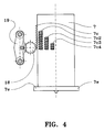
- the external wall of the striker has four parallel length racks each corresponding to percussion delays of one second, seven tenths, four tenths and one tenth of second.
- an impact detector module will be used omnidirectional with adjustable sensitivity, for impactful mode and the striking-fusing mode, housed in an axial bore of the body cylindrical of the cap, comprising a master cylinder associated with a first spring, a counter-cylinder associated with a second spring, a transverse detection ball inserted between the master cylinder and counter cylinder, two balls of locking and unlocking of the module controlled by the axial movement of the striker and another ball of functional locking and unlocking of the module preventing or authorizing its operation by the action of the selector.
- the module's transverse detection ball impact detector consists of a dense material of the type tungsten.
- the selector has in the safety position means prohibiting the extraction of a locking pin a spoon and an upstream striker controlling the firing of the upstream part of the chain.
- the selector being in striking-fusing position, three additional rotations successive in the same direction of the selector causing alignment of the timing module gear wheel with respectively, the second rack of the striker corresponding to a percussion delay of seven tenths, the third striker rack corresponding to a delay of percussion of four tenths and the fourth rack of the striker corresponding to a percussion delay of one tenth second.
- the module of self-destruction associated with the striker control means cause the ignition of the downstream part of the chain followed of the explosion of the object.
- An advantage of an igniter plug according to the invention resides in the compactness of its structure and the modularity of its constituent elements, significantly simplifying the conditions of shooting and the manufacturing stages encountered during a largely automated production.
- This igniter plug has several operating modes offers optimized shooting and storage security.
- the interruption element of the pyrotechnic chain judiciously arranged within the downstream part thereof is independent of the environment for better efficiency in case of accidental initiation of the upstream part of the chain, during transport or storage of the associated plug to the pyrotechnic charge.
- This interrupt element can only be moved by voluntary operator intervention. It follows that purely manual train alignment and misalignment pyrotechnic, cannot result from the conjunction of elements aggressive exteriors.
- Another advantage is the positioning in the center of the main load of the main initiation relay, ensuring thus an isotropic detonation of the pyrotechnic charge.
- an igniter plug three functions of substantially cylindrical shape comprising at its lower part a case 26 provided with an external thread to adapt the cap on a hand grenade for example, no represented. On this lower part, is mounted mobile in rotation the main part of the cap surmounted by the head of the plug comprising conventional means for initiating a pyrotechnic chain such as a pin 34 and a spoon 22 controlling an upstream striker 29.
- the present invention does not relate not on these known conventional means.
- the main part of the cap includes three pieces hollow cylindrical 23, 24 and 25 superimposed coaxial and movable in rotation with respect to each other. She has two axial bores 2 and 37. Central bore 2 is extends into the fixed case 26 screwed into the grenade.
- This bore 2 communicates with a coaxial bore of the fixed case 26, containing the downstream part 4 of the pyrotechnic chain.
- the lower part of the striker 7 has three lugs 7e exteriors distributed at 120 ° on its periphery, suitable for housing in the three sets of lights 20a, 20b and 20c of the module neutralization.
- On the inner face of this lower part of the striker 7 is fixed an axial scroll 7d communicating with the exhaust vent 5c of the piston 5 in the low position and driving the striker in rotation under the effect of gases produced by the combustion of the pyrotechnic composition 5a and 5b contained in the piston 5.
- This neutralization module also includes a lug 21 axial neutralization indication, protruding at the outside of the module through a recess 26a of this last when one of the three pins 7e of the striker is in support on its upper part. In the extended position, this lug 21 constitutes a stop preventing the relative rotation of the module 20 and the selector 23 relative to the fixed case 26, and indicating to the operator the neutralization position occupied by the striker.
- a ramp 7a, 7b ( Figure 3) is dug in the wall cylindrical external of the striker 7. It comprises a part longitudinal 7a extended by a helical part 7b in which is engaged a guide member consisting of a ball 9 movable in rotation in an open housing made in the body 24 of the plug and protruding into the bore central 2 of the plug.
- FIG. 3 there is shown in broken lines, the different positions taken by the ball 9 in the ramp longitudinal 7a and helical 7b during the movement of the striker.
- This ball successively occupies positions 9a, 9b, 9c and 9d after respectively a first axial displacement of the striker, a second rotary and axial movement corresponding to the armed position of the striker, a third displacement caused by the action of the self-destruct module, a fourth displacement leading to percussion of self-destruction or of the fused operating mode.
- a timer module is placed, through a manhole made in the body 24 of the plug, in the external part cylindrical 23 forming the head of the plug used for select the different operating modes of the machine pyrotechnic.
- This timer module integral with the selector 23 by any known means, is rotated by the latter around the striker, to align with one of the four axial racks of the striker in striking-fusing mode.
- This purely mechanical timer module includes a oscillator 19 regulating the rotation of one or more wheels teeth 18 that can mesh in one of the four racks, depending on the duration of the percussion delay chosen by the operator from selector 23.
- An omnidirectional sensitive impact detector module adjustable is mounted in the second axial bore 37 which can have a diameter equal or not to that of the central bore 2.
- This second bore 37 is formed in the body 24 of the plug short distance from the central bore 2.
- the locks of these two elements of the module are provided by the striker which keeps each of the balls 15 and 16 engaged in the groove master cylinder and counter cylinder.
- the master cylinder 10 is in contact with ball 9 and maintains engagement in the ramp 7a, 7b of the striker.
- This master cylinder has two notches 10a allowing, after axial displacement of the latter caused by a shock longitudinal or transverse, the exit of the ball 9 from the ramp releasing the striker.
- the selector 23 constituted by the cylindrical head of the plug has at its lower part an elastic lock 23a which just snaps into a circular notch in the fixed case 26.
- On the periphery of the upper part of the selector 23 (FIG. 8A) are arranged four marks principal correspondents for security positions, Fusing, impactful and impactful-fusing operation. The operator accesses each of these four marks by rotation successive 90 °.
- the selector In the striking-fusing position, the selector has three secondary references, accessible by rotation successive 20 ° for example, corresponding to the different percussion delays described above.
- An external element around the upper part of the case 26 has a circular rib 26e ( Figures 5 and 8) trapping, using the elastic lock 23a of the selector safety position, part of a ring 34a connected to the pin 34, to prevent the extraction of the latter only when the selector is in the safety position.
- This part downstream 4 comprises from top to bottom: a percussion primer 4a, a charge 4b in lead azide, a priming relay 4c in hexogen, a cylinder element 27 for interrupting the chain then a main 4d hexogen relay ( Figures 5 to 7).
- This element 27 of interruption or misalignment of the train pyrotechnic consists of a cylinder pierced with an orifice axial and preferably containing an intermediate relay load as a secondary explosive of the hexogenic type. It is fixed by everything known means on a cylindrical barrel 28 driven in rotation by mechanical means from a radial position to a position axial of the element and vice versa.
- These mechanical means activated by rotation only manual of the selector 23 constituted by the head of the plug, have an internal cylindrical part 25 the part of which lower 25a is housed in the case 26 and the upper part containing the neutralization module is rotated by the body 24 of the cap covered by the selector 23.
- these means mechanical include a helical groove 31 made in the case 26 associated with a pin 30 of the movable barrel 28 in rotation in the lower end 25a of the internal part 25, so as to rotate the element 90 ° 27 by a joint 45 ° rotation of the body 24 and the selector, in the initial safety position.
- the upper part of part 25 is locked with the case fixed 26, in order to keep the alignment of the pyrotechnic train for the three operating modes.
- the return to position of safety of selector 23 unlocks part 25 of case 26 and causes the pyrotechnic train to be misaligned by returning to radial position of the element 27.
- the assembly helical groove 31 associated with the tenon 30 is replaced by a gear wheel 32 of barrel 28 geared into a rack 33 case 26 circular to ensure alignment and misalignment of the pyrotechnic train by 90 ° rotation of the interrupting element 27.
- the operation of the firing device according to the invention is as follows.
- the igniter plug being mounted in the safety position on a hand grenade type pyrotechnic device for example, the operator chooses one of the three operating modes in turning the head 23 of the cap by hand around the case fixed 26 screwed on the machine.
- the operator can rotate the selector 23 in one direction only by exerting pressure on the elastic lock 23a snapped into the circular notch of the fixed case 26, to select the desired operating mode.
- the three cylindrical parts 23, 24 and 25 can rotate simultaneously with respect to the fixed case 26, thanks to two cams 23d and 24b, forming part of the respective ends of the parts 23 and 24, provided with two tenons 23c and 24a sliding in corresponding grooves 26b and 26c of the case ( Figures 9 at 9B).
- misalignment of the pyrotechnic train can again be done by reverse rotation and back in safety position.
- striker 7 is linked in rotation with the cylindrical part 24 by the ball 9 engaged in the ramp 7a, 7b thereof.
- the operator can extract the pin 34 by pulling on the ring 34a released by the erasure of the circular groove 26e of the case 26, the part cylindrical 24 being locked with the upper part of the internal part 25 by snap-fastening at the rib 26c and of the elastic cam 24b associated with its stud 24a.
- the functional locking ball 17 comes out of the groove of the master cylinder 10 and is housed in the internal circular groove 23b of the selector to activate the impact detector module.
- the timer module stays away from the racks 7c of the striker.
- the part 24 is locked on the case 26 by a lug 24c in the groove 26f of the case.
- the selector 23, associated with the timer module revolves around the body 24 of the plug.
- the gear wheel 18 of the module timer is aligned with the first rack 7c of the striker corresponding to a percussion delay of one second, and the functional locking ball 17 remains free for leave the impact detector module active.
- the other angular positions of the selector which can for example be 300 °, 320 ° and 340 ° correspond respectively to the alignment of the toothed wheel 18 with the racks 7v2, 7v3, and 7v4 for percussion delays of seven tenths, four tenths and one tenth of a second. In these last three positions, the impact detector module also remains active. Each of these four positions is indexed by cam 23c.
- the operator extracts pin 34 and launches the grenade.
- the spoon 22 releases the upstream striker 29 which strikes the primer 3a of the upstream part 3 of the pyrotechnic chain ( Figure 11). The following actions follow one another.
- the combustion of the pyrotechnic delay 3b ignites the charge reinforcer 3c which generates gases causing displacement axial of the piston 5 compressing the spring 6.
- the striker 7 forced by the part helical ramp with one rotation, allows the three 7th pins of the striker to move away from the three lights 20b long functional neutralization of the module neutralization, to position itself next to the three lights 20c outlets, thus authorizing effective arming of the device.
- This original trick allows you to both control the presence of the ball 9 guiding the striker, as well as the triggering of the percussion, and the integrity of the impact detector module. If one had failed, the striker would have dived into neutralization lights functional 20b.
- a longitudinal impact, producing an axial displacement of the master cylinder 10, ball 14 and counter cylinder 12 assembly, or transverse, radially moving the ball 14, drives necessarily the axial displacement of the master cylinder 10 of which one of the two notches 10a allows the ball 9 to come out of the helical part 7b of the ramp causing the release of the striker ( Figure 12).
- the striker In its movement towards the downstream part 4 of the chain pyrotechnic, the striker is delayed by the module timer. Indeed, the rack 7c of the striker (or one of the shorter racks 7v2, 7v3 and 7v4, depending on the selected impact delay) comes into contact with the wheel toothed 18 which strongly brakes the striker ( Figures 11B and 12).
- the striker After a delay, depending on the length of the rack, the striker is finally released and will ignite the downstream part 4 of the chain by striking the primer 4a.
- the propellant charge 3c ignited the composition delay 5a.
- the composition reinforcer 5b generates gases, the flow of which through the volute 7d forces the striker to a new rotation.
- the upper end of the helical part 7b of the ramp then presents itself to the ball 9 which disappears (FIG. 3).
- This additional striker rotation has misaligned the rack 7c with the toothed wheel 18 of the timer module so that the percussion of self-destruction is instantaneous.
Landscapes
- Engineering & Computer Science (AREA)
- General Engineering & Computer Science (AREA)
- Automotive Seat Belt Assembly (AREA)
- Air Bags (AREA)
- Arrangements Of Lighting Devices For Vehicle Interiors, Mounting And Supporting Thereof, Circuits Therefore (AREA)
- Steering Devices For Bicycles And Motorcycles (AREA)
Claims (27)
- Zündvorrichtung einer pyrotechnischen Ladung, vom Typ Zünder, insbesondere für Handgranaten, welche eine aus einer zweiteiligen, d.h. einem vorderen und einem hinteren Teil (3, 4) bestehende, in einer im Zünderkörper (24) angebrachten axialen Bohrung (2) gelagerte pyrotechnische Kette enthält, wobei der hintere Teil (4) durch einen zwischen den beiden Teilen der Kette angebrachten, mit Steuerelementen, welche mit einer Verriegelvorrichtung zusammenwirken, verbundenen axialen Zündnadel (7) gezündet wird, dadurch gekennzeichnet, daß die mechanischen Steuerelemente (5, 6) der Zündnadel zwischen dem vorderen Teil der Kette und der Zündnadel angebracht sind, um die Zündnadel (7) in einer axialen und sich um ihre Achse drehenden Bewegung anzutreiben, unter dem Druck der von der Initiation des vorderen Teils (3) der pyrotechnischen Kette erzeugten Gase.
- Vorrichtung gemäß Patentanspruch 1, dadurch gekennzeichnet, daß die mechanischen Steuermittel (5,6) der Zündnadel mit einem Führungsorgan (9) zusammenwirken, welches auf Ebene der Bohrung (2) des Zünderkörpers (24) in einer Rampe (7a, 7b) liegt ist.
- Vorrichtung gemäß Patentanspruch 2, dadurch gekennzeichnet, daß die Steuerelemente der zylinderförmigen, hohlen Zündnadel (7) aus einer Feder (6) und einem axial zur mittleren Bohrung (2) gleitenden Kolben (5) bestehen, welche in einem festen, zylinderförmigen, den vorderen Teil der pyrotechnischen Kette enthaltenden inneren Körper (1) liegen, wobei dieser Körper zum Teil in die Zündnadel (7) eingepaßt ist.
- Vorrichtung gemäß Patentanspruch 3, dadurch gekennzeichnet, daß das Verriegelungselement der Zündnadel (7) mit dem inneren Körper (1) aus einer Kugel (8) besteht, welche in einer Lagerung des Körpers (1) herausragt und es dem Zünder ermöglicht, von einer ursprünglichen gesicherten Position, in welcher der Kolben (5) die Kugel in eine innere kreisförmige Nute (7f) des Zünders gedrückt hält, nach Axialverschiebung des Kolbens in eine entsicherte Position überzugehen, in welcher die geradlinig mit einer kreisförmigen Nute (5d) des Kolbens positionierte Kugel (8) aus der inneren kreisförmigen Nute (7f) des Zünders heraustritt und diesen freigibt.
- Vorrichtung gemäß Patentanspruch 4, dadurch gekennzeichnet, daß das Führungsorgan aus einer Kugel (9) besteht, welche in der mittleren Bohrung (2) in der an der Außenseite des Zünders angebrachten Rampe herausragt; die Rampe umfaßt einen geradlinigen (7a), durch einen schneckenförmige Abschnitt verlängerten Abschnitt, so daß eine erste Axialverschiebung durchgeführt wird, gefolgt von einer zweiten gleichzeitig rotativen und axialen Verschieben desselben Zünders bewirkt wird.
- Vorrichtung gemäß Patentanspruch 5, dadurch gekennzeichnet, daß sie einen Neutralisierungssatz (20) des Zünders (7) enthält, welcher zwischen dem Zünder und dem hinteren Abschnitt (4) der pyrotechnischen Kette angeordnet ist.
- Vorrichtung gemäß Patentanspruch 6, dadurch gekennzeichnet, daß der zylinderförmige Neutralisierungssatz (20) drei Öffnungsserien (20a, 20b, 20c) mit unterschiedlichen Längen, welche auf der Peripherie des Satzes angeordnet sind und als Lagerung für mindestens eine Nocke (7e) des Zünders (7) dienen, aufweist.
- Vorrichtung gemäß Patentanspruch 7, dadurch gekennzeichnet, daß der Zünder drei äußere Nocken (7e), bei 120° auf seiner Peripherie und geradlinig mit einer der drei ebenfalls auf dem Satz verteilten Öffnungsserien angeordnet, enthält, um entweder eine Lagerungs- und Transportneutralisierung bei gesicherter Position des Zünders, eine funktionelle Neutralisierung in entsicherter Position des Zünders, oder das Zünden des hinteren Abschnitts (4) der Kette zu gewährleisten.
- Vorrichtung gemäß Patentanspruch 8, dadurch gekennzeichnet, daß sie einen Selbstzerlegesatz umfaßt, welcher eine gaserzeugende, durch den vorderen Abschnitt der Kette initiierte Komposition (5a, 5b) im Kolben (5), einen im Kolben angebrachten Auslaß (5), der nach Verschieben des Kolbens geradlinig mit einer am Zünder befestigten Axialspirale (7d) liegt, enthält, um unter Einwirkung der Steuerelemente eine rotative und axiale Verschiebung des Zünders, gefolgt von der Zündung des hinteren Abschnitts (4) der Kette, zu verursachen.
- Vorrichtung gemäß Patentanspruch 9, dadurch gekennzeichnet, daß die im Kolben (5) enthaltene gaserzeugende Komposition aus einer Verzögerungskomposition (5a) in Verbindung mit einer Verstärkungskomposition (5b) besteht.
- Vorrichtung gemäß irgendeinem der vorstehenden Patentansprüche, einschließ lich einem axialen Unterbrechungselement der pyrotechnischen Kette, angebracht im hinteren Abschnitt der in einem zylinderförmigen Etui (26) gelagerten Kette und von mechanischen Hilfsmitteln in Drehung versetzt, dadurch gekennzeichnet, daß die mechanischen Antriebshilfsmittel des Elementes von der alleinigen Drehung des Zünderkopfes (23) aktiviert werden, wodurch ein manuelles Ausrichten und Fluchtabweichen der Kette ermöglicht werden.
- Vorrichtung gemäß Patentanspruch 11, dadurch gekennzeichnet, daß das Unterbrechungselement aus einem mit einer axialen Öffnung versehenen Zylinder (27) besteht, welcher an einer Ausrichtungshülse (28) befestigt ist, die in Rotation von den mechanischen Hilfsmitteln von einer Radialposition in eine Axialposition des Zylinders und umgekehrt versetzt wird.
- Vorrichtung gemäß Patentanspruch 12, dadurch gekennzeichnet, daß die mechanischen Drehantriebshilfsmittel der Hülse (28) aus einem zylinderförmigen, drehbaren inneren Teil (25) besteht, welcher teilweise im Etui (26) gelagert und über sein unteres Ende (25a) mit der Hülse verbunden ist, und dessen oberer Teil von der Drehung des Körpers (24) unddes Kopfes (23) des Zünders angetrieben wird.
- Vorrichtung gemäß Patentanspruch 13, dadurch gekennzeichnet, daß die Hülse mit einem Zapfen (30) ausgestattet ist, welcher in einer im zylinderförmigen Etui (26) ausgeführten schneckenförmigen Nute (31) rastet und eine Drehung des Zylinders um 90° gewährleistet.
- Vorrichtung gemäß Patentanspruch 13, dadurch gekennzeichnet, daß die Hülse (28) mit Zähnen (32) ausgestattet ist, welche in eine Zahnstange (33) des Etuis eingreifen, um eine Drehung des Zylinders um 90° zu gewährleisten.
- Vorrichtung gemäß irgendeinem der vorstehenden Patentansprüche, dadurch gekennzeichnet, daß der hintere Abschnitt (4) der pyrotechnischen Kette nacheinander eine Aufschlagzündung (4a), eine Ladung (4b) aus Bleinitrid, ein Zündrelais (4c) aus Hexogen, das Unterbrechungszylinderelement (27) und schließlich ein Hauptrelais (4d) aus Hexogen enthält.
- Vorrichtung gemäß Patentanspruch 16, dadurch gekennzeichnet, daß der Unterbrechungszylinder (27) ebenfalls eine Relaiszwischenladung aus untergeordnetem Sprengstoff vom Typ Hexogen enthält.
- Anwendung der Zündvorrichtung einer pyrotechnischen Ladung gemäß irgendeinem der vorstehenden Patentansprüche, an einem Zünder mit drei Funktionen, welcher die Betriebsarten Brennzündung, Aufschlagzündung oder Aufschlag-/Brennzündung der Ladung ermöglicht, z.B. mit einem Wähler der Betriebsarten, einen Aufschlagdetektionssatz und einem Verzögerungssatz, dadurch gekennzeichnet, daß der Wähler aus der äußeren zylindrischen Wand (23) des Zünderkopfes besteht, rotativ beweglich um den die mittlere Bohrung (2) enthaltenen zylinderförmigen Körper (24) des Zünders.
- Zünder gemäß Patentanspruch 18, dadurch gekennzeichnet, daß der mit dem Wähler (23) fest verbundene Verzögerungssatz einen mechanischen Oszillator (19) enthält, welcher die Drehung von mindestens einem Zahnrad (18), eingreifend in mindestens eine axiale, an der Außenwand des Zünders befestigte Zahnstange (7) steuert, um in der Betriebsart Aufschlag-/Brennzündung eine Aufschlagverzögerung zu erreichen.
- Zünder gemäß Patentanspruch 19, dadurch gekennzeichnet, daß die Auß enwand des Zünders (7) vier parallele, unterschiedlich lange Zahnstangen (7c, 7c2, 7c3, 7c4) enthält, welche jeweils einer Aufschlagverzögerung von einer Sekunde, sieben Zehntel, vier Zehntel und ein Zehntel Sekunde entsprechen.
- Zünder gemäß Patentanspruch 20, dadurch gekennzeichnet, daß der omnidirektionale Aufschlagdetektionssatz mit einstellbarer Empfindlichkeit, angewandt für die Betriebsarten Aufschlagzündung und Aufschlag-/Brennzündung, gelagert in einer axialen Bohrung (37) des zylinderförmigen Körpers (24) des Zünders, einen mit einer ersten Feder (11) verbundenen Hauptzylinder (10), einen mit einer zweiten Feder (13) verbundenen Gegenzylinder (12), eine zwischen dem Hauptzylinder und dem Gegenzylinder positionierte Transversaldetektionskugel (14), zwei Kugeln (15) und (16) zur Verriegelung und Entriegelung des Satzes, gesteuert von der Axialverschiebung der Zündnadel (7), und eine Kugel zur funktionellen Verriegelung und Entriegelung (17) des Satzes, welche seine Funktion durch Betätigung des Wählers (23) sperrt oder freigibt, enthält.
- Zünder gemäß Patentanspruch 21, dadurch gekennzeichnet, daß die Transversaldetektionskugel (14) des Aufschlagdetektionssatzes aus einem dichten Material vom Typ Wolfram besteht.
- Zünder gemäß Patentanspruch 22, ausgestattet mit einem mit einem Sperrstift (34) verbundenen Ring (34a) zum Verriegeln des Löffels (22) und einem vorderen Zünder (29), welcher die Zündung des vorderen Abschnitts (3) der Kette steuert, dadurch gekennzeichnet, daß er in der gesicherten Position des Wählers (23) Hilfsmittel enthält, welche das Herausziehen des Sperrstifts (34) verbieten.
- Zünder gemäß Patentanspruch 23, dadurch gekennzeichnet, daß die Hilfsmittel, welche das Herausziehen des Sperrstifts (34) in gesicherter Position des Wählers verbieten, aus einer kreisförmigen Rippe (26e) des Etuis (26) und einem elastischen Riegel (23a) des Wählers, welcher einen Teil des Ringes (34a) einsperrt, bestehen.
- Zünder gemäß Patentanspruch 24, dadurch gekennzeichnet, daß der rotative Wähler (23) eine ursprüngliche gesicherte Position und durch aufeinanderfolgende Drehungen um 90° mindestens drei verschiedene Positionen einnimmt, wobei jede einer der Betriebsarten entspricht:in gesicherter Position ist der Sperrstift (34) verriegelt, der pyrotechnische Zug ist von dem in Radialposition gehaltenen Element (27) unterbrochen, der Zünder (7), dessen drei Nocken (7e) sich geradlinig mit den drei kurzen Sicherheitsöffnungen (20a) befinden, ist von der in der inneren kreisförmigen Nute (7f) des Zünders rastenden Kugel (8) verriegelt, das Zahnrad (18) des Verzögerungssatzes befindet sich in Abstand zu den Zahnstangen (7c) des Zünders, und der Aufschlagdetektionssatz ist von den beiden Kugeln (15) und (16) verriegelt, welche jeweils den Hauptzylinder (10) und den Gegenzylinder (12) unter der Aktion des Zünders (7) in der ursprünglichen Position blockiert, außerdem blockiert die vom Wähler (23) festgehaltene Kugel für die funktionelle Verriegelung (17) ebenfalls den Hauptzylinder (10),eine erste Drehung des Wählers um 90°, welche der Brennzündungsfunktion der Ladung entspricht, verursacht nacheinander das Entriegeln des Sperrstifts (34), um dessen Herausziehen zu ermöglichen, das Ausrichten des pyrotechnischen Zuges durch Drehung des Unterbrechungselementes (27) um 90°, und die relative Drehung des Zünders (7) im Verhältnis zum Neutralisierungssatz (20) unter Positionierung der drei Nocken (7e) des Zünders geradlinig mit den drei längeren Öffnungen (20b) des Satzes, welches der funktionellen Neutralisierungsposition des Zünders entspricht, während der Verzögerungssatz und der Aufschlagdetektionssatz unwirksam bleiben,eine zweite Drehung des Wählers um 90°, welche der Betriebsart Aufschlagzündung entspricht, verursacht zusätzlich das Freisetzen der Kugel zum funktionellen Verriegeln (17) des Aufschlagdetektionssatzes, indem sie sich in die innere kreisförmige Nute (23b) des Wählers lagert, um den Satz zu aktivieren,eine dritte Drehung des Wählers um 90°, welche der Betriebsart Aufschlag-/Brennzündung entspricht, verursacht zusätzlich das Ausrichten des Zahnrads (18) des Verzögerungssatzes mit der ersten Zahnstange (7c) des Zünders, welches einer Aufschlagverzögerung von einer Sekunde entspricht, während der Aufschlagdetektionssatz aktiv bleibt.
- Zünder gemäß Patentanspruch 25, dadurch gekennzeichnet, daß der Wähler (23) in der Position Aufschlag-/Brennzündung steht, drei zusätzliche, aufeinanderfolgende Drehungen des Wählers in gleicher Richtung das Ausrichten des Zahnrads (18) des Verzögerungssatzes verursacht, wobei jeweils die zweite Zahnstange (7c2) des Zünders einer Aufschlagverzögerung von sieben Zehntel, die dritte Zahnstange (7c3) des Zünders einer Aufschlagverzögerung von vier Zehntel Sekunde und die vierte Zahnstange (7c4) des Zünders einer Aufschlagverzögerung von ein Zehntel Sekunde entspricht.
- Zünder gemäß irgendeinem der Patentansprüche 21 bis 26, dadurch gekennzeichnet, daß, wenn der Wähler (23) in der Position Aufschlagzündung und Aufschlag-/Brennzündung steht und der Aufschlagdetektionssatz unwirksam ist, der mit den Steuerelementen (5,6) des Zünders verbundene Selbstzerlegesatz (5a, 5b, 5c, 7d) das Zünden des hinteren Abschnitts (4) der Kette, gefolgt von der Explosion des Geschosses, verursacht.
Applications Claiming Priority (2)
| Application Number | Priority Date | Filing Date | Title |
|---|---|---|---|
| FR9407381 | 1994-06-16 | ||
| FR9407381A FR2721394B1 (fr) | 1994-06-16 | 1994-06-16 | Dispositif de mise à feu d'une charge pyrotechnique du type bouchon allumeur notamment pour grenade à main ayant trois modes de fonctionnement. |
Publications (2)
| Publication Number | Publication Date |
|---|---|
| EP0687888A1 EP0687888A1 (de) | 1995-12-20 |
| EP0687888B1 true EP0687888B1 (de) | 1998-12-09 |
Family
ID=9464289
Family Applications (1)
| Application Number | Title | Priority Date | Filing Date |
|---|---|---|---|
| EP95401323A Expired - Lifetime EP0687888B1 (de) | 1994-06-16 | 1995-06-08 | Abfeuervorrichtung für eine pyrotechnische Ladung mit einem Zünderkopf, insbesondere für Handgranateur, mit drei Funktionsweisen |
Country Status (8)
| Country | Link |
|---|---|
| US (1) | US5635667A (de) |
| EP (1) | EP0687888B1 (de) |
| CA (1) | CA2151873A1 (de) |
| DE (1) | DE69511906T2 (de) |
| DK (1) | DK0687888T3 (de) |
| ES (1) | ES2126846T3 (de) |
| FR (1) | FR2721394B1 (de) |
| NO (1) | NO317317B1 (de) |
Families Citing this family (19)
| Publication number | Priority date | Publication date | Assignee | Title |
|---|---|---|---|---|
| WO1997017587A1 (de) * | 1995-11-08 | 1997-05-15 | Oregon Etablissement Für Patentverwertung | Zünder, insbesondere für handgranaten |
| ES2136485B1 (es) * | 1995-12-29 | 2000-05-16 | Instalaza Sa | Espoleta mecano-electronica para granada de mano. |
| US6272995B1 (en) * | 1999-09-14 | 2001-08-14 | Kdi Precision Products, Inc. | High precision fuze for a munition |
| US6631667B1 (en) | 2000-10-25 | 2003-10-14 | Lockheed Martin Corporation | Explosive-bolt-activated spring-loaded actuation device |
| FR2816401B1 (fr) | 2000-11-09 | 2002-12-20 | France Etat Armement | Moyens d'initiation pyrotechnique retardateurs |
| US7213518B2 (en) * | 2003-02-21 | 2007-05-08 | Engel Ballistic Research, Inc. | Modular electronic fuze |
| DE10316875B4 (de) * | 2003-04-11 | 2005-07-21 | Diehl Bgt Defence Gmbh & Co. Kg | Mechano-elektrischer Zünder für eine Handgranate |
| KR100616471B1 (ko) | 2004-12-30 | 2006-08-29 | 국방과학연구소 | 신호인가 잠금장치 |
| US7191707B1 (en) * | 2005-11-15 | 2007-03-20 | Davis Russell J | Spherical rolling explosive ordinance |
| DE102009059951B4 (de) * | 2009-12-22 | 2012-05-03 | Diehl Bgt Defence Gmbh & Co. Kg | Handgranatenzünder |
| CN102278917B (zh) * | 2010-05-17 | 2015-08-19 | 义高潮 | 一种手榴弹引信的勤务保险机构 |
| US9140528B1 (en) | 2010-11-16 | 2015-09-22 | Lockheed Martin Corporation | Covert taggant dispersing grenade |
| US10054410B2 (en) | 2011-08-04 | 2018-08-21 | James Y. Menefee, III | Cartridge for handheld payload launcher system |
| WO2013020025A2 (en) | 2011-08-04 | 2013-02-07 | Polywad, Inc. | Handheld payload launcher system |
| US9423222B1 (en) | 2013-03-14 | 2016-08-23 | Lockheed Martin Corporation | Less-than-lethal cartridge |
| US9200876B1 (en) * | 2014-03-06 | 2015-12-01 | Lockheed Martin Corporation | Multiple-charge cartridge |
| RU203366U1 (ru) * | 2020-07-09 | 2021-04-01 | Федеральное государственное казенное военное образовательное учреждение высшего образования "ВОЕННАЯ АКАДЕМИЯ МАТЕРИАЛЬНО-ТЕХНИЧЕСКОГО ОБЕСПЕЧЕНИЯ имени генерала армии А.В. Хрулева" Министерства обороны Российской Федерации | Взрыватель дистанционного подрыва для ручных гранат |
| US11598618B1 (en) | 2021-10-07 | 2023-03-07 | Goodrich Corporation | Time delay systems, methods, and devices |
| US12017750B2 (en) * | 2022-07-08 | 2024-06-25 | The Boeing Company | Pyrotechnic devices and firing mechanisms for aircraft canopy jettison |
Family Cites Families (18)
| Publication number | Priority date | Publication date | Assignee | Title |
|---|---|---|---|---|
| US2763212A (en) * | 1950-01-24 | 1956-09-18 | James F Mccaslin | Selective time-impact fuze for hand grenades |
| BE532090A (de) * | 1953-09-25 | |||
| US3148621A (en) * | 1958-06-14 | 1964-09-15 | Industrial Holding Ets | Projectile fuze |
| CH368076A (fr) * | 1961-02-24 | 1963-03-15 | Mefina Sa | Fusée pour projectile |
| DE1428801A1 (de) * | 1964-03-19 | 1969-04-30 | Prb Nv | Zuender |
| CH426556A (de) * | 1965-02-18 | 1966-12-15 | Stamag Ag | Aufschlagzünder-Handgranate |
| NL6901794A (de) * | 1969-02-05 | 1970-08-07 | ||
| US3823669A (en) * | 1973-01-29 | 1974-07-16 | Us Army | Fail-safe hand grenade |
| CH607792A5 (de) * | 1976-05-28 | 1978-10-31 | Sarmac Sa | |
| US4078496A (en) * | 1976-11-05 | 1978-03-14 | The United States Of America As Represented By The Secretary Of The Army | Antirunaway device for hand grenade fuze |
| FR2458790A1 (fr) * | 1979-06-08 | 1981-01-02 | Alsetex | Bouchon allumeur de grenade polyvalent a securite de lancement |
| FR2465189A1 (fr) * | 1979-09-17 | 1981-03-20 | Ruggieri Ets | Bouchon allumeur pour grenade |
| FR2500619A1 (fr) * | 1981-02-20 | 1982-08-27 | France Etat | Bouchon allumeur pour grenade a temporisateur pyrotechnique |
| FR2517048A1 (fr) | 1981-11-23 | 1983-05-27 | Luchaire Sa | Bouchon allumeur pour grenade a main |
| WO1987001193A1 (fr) * | 1985-08-22 | 1987-02-26 | Oregon Etablissement Für Patentverwertung | Fusee a double effet pour projectiles |
| IL81198A0 (en) * | 1987-01-08 | 1987-08-31 | Israel State | Safetied demolition charge fuse |
| FR2682471B1 (fr) | 1991-10-15 | 1995-05-24 | Alsetex Armement Etudes | Bouchon allumeur a securite de stockage par interruption de chaine pyrotechnique. |
| US5335803A (en) * | 1992-09-09 | 1994-08-09 | Brien Diana A O | Rotatable food tray for outdoor patio furniture |
-
1994
- 1994-06-16 FR FR9407381A patent/FR2721394B1/fr not_active Expired - Fee Related
-
1995
- 1995-06-08 DK DK95401323T patent/DK0687888T3/da active
- 1995-06-08 DE DE69511906T patent/DE69511906T2/de not_active Expired - Fee Related
- 1995-06-08 ES ES95401323T patent/ES2126846T3/es not_active Expired - Lifetime
- 1995-06-08 EP EP95401323A patent/EP0687888B1/de not_active Expired - Lifetime
- 1995-06-15 NO NO19952371A patent/NO317317B1/no not_active IP Right Cessation
- 1995-06-15 CA CA002151873A patent/CA2151873A1/fr not_active Abandoned
- 1995-06-15 US US08/490,813 patent/US5635667A/en not_active Expired - Lifetime
Also Published As
| Publication number | Publication date |
|---|---|
| DK0687888T3 (da) | 1999-08-16 |
| DE69511906T2 (de) | 1999-12-02 |
| NO952371L (no) | 1995-12-18 |
| CA2151873A1 (fr) | 1995-12-17 |
| FR2721394A1 (fr) | 1995-12-22 |
| NO317317B1 (no) | 2004-10-11 |
| NO952371D0 (no) | 1995-06-15 |
| FR2721394B1 (fr) | 1996-08-09 |
| ES2126846T3 (es) | 1999-04-01 |
| DE69511906D1 (de) | 1999-10-07 |
| EP0687888A1 (de) | 1995-12-20 |
| US5635667A (en) | 1997-06-03 |
Similar Documents
| Publication | Publication Date | Title |
|---|---|---|
| CA2151873A1 (fr) | Dispositif de mise a feu d'une charge pyrotechnique du type bouchon allumeur notamment pour grenade a main ayant trois modes de fonctionnement | |
| EP0411996B1 (de) | Zündvorrichtung einer Zündkette für Submunitionskörpern | |
| WO2001077608A1 (fr) | Verrou pour levier de bouchon allumeur | |
| CH628422A5 (fr) | Subprojectile destine a etre expulse d'un projectile. | |
| FR2458790A1 (fr) | Bouchon allumeur de grenade polyvalent a securite de lancement | |
| FR2465189A1 (fr) | Bouchon allumeur pour grenade | |
| WO2023046327A1 (fr) | Fusee mecanique auto-percutante pour une munition non girante | |
| EP0230196B1 (de) | Geschoss mit pyrotechnischer Ladung | |
| EP0234159B1 (de) | Geschoss mit pyrotechnischer Ladung und Mittel zu deren verzögerten Zündung | |
| FR2501360A1 (fr) | Cartouche a actionnement pyrotechnique de charge utile explosant apres le rebond | |
| EP1500902B1 (de) | Selbst-Zerlegerzünder für drallstabilisierte Geschosse | |
| EP0233431B1 (de) | Patrone mit einem eine pyrotechnische Ladung tragenden Geschosskörper | |
| EP4176225B1 (de) | Zünder mit selbstzerstörungsvorrichtung für ein kreiselgeschoss | |
| FR2500619A1 (fr) | Bouchon allumeur pour grenade a temporisateur pyrotechnique | |
| FR2726359A1 (fr) | Fusee d'impact a double securite | |
| CH642167A5 (fr) | Projectile d'exercice. | |
| EP0206978B1 (de) | Geschossaufschlagzünder | |
| FR2699660A1 (fr) | Système d'amorçage et d'auto-destruction d'une munition, en particulier d'une sous-munition destinée à être éjectée d'un obus cargo avec un mouvement de rotation propre autour d'un axe. | |
| FR2500621A1 (fr) | Bouchon allumeur pour grenade, a securite amelioree | |
| EP0075496A1 (de) | Vorkehrungen zum Sichern und Schärfen an Unterwasserzündern | |
| EP0278837B1 (de) | Zeitzünder für beliebige Aufschlagrichtung für Munition zum Abschuss aus Feuerwaffen, insbesondere für Granaten | |
| FR2670280A1 (fr) | Arme legere automatique. | |
| FR2599135A1 (fr) | Munition largable a positionnement automatique, notamment mine dispersable antipersonnel bondissante | |
| FR2669106A1 (fr) | Bouchon allumeur de grenade a main polyvalent, a securite de lancement et a fonctions percutante et fusante. | |
| FR2500620A1 (fr) | Bouchon allumeur pour grenade a fonctionnement fusant ou fusant-percutant |
Legal Events
| Date | Code | Title | Description |
|---|---|---|---|
| PUAI | Public reference made under article 153(3) epc to a published international application that has entered the european phase |
Free format text: ORIGINAL CODE: 0009012 |
|
| AK | Designated contracting states |
Kind code of ref document: A1 Designated state(s): BE DE DK ES GB IT LU NL PT SE |
|
| 17P | Request for examination filed |
Effective date: 19950627 |
|
| 18D | Application deemed to be withdrawn |
Effective date: 19960621 |
|
| D18D | Application deemed to be withdrawn (deleted) | ||
| GRAG | Despatch of communication of intention to grant |
Free format text: ORIGINAL CODE: EPIDOS AGRA |
|
| GRAG | Despatch of communication of intention to grant |
Free format text: ORIGINAL CODE: EPIDOS AGRA |
|
| GRAH | Despatch of communication of intention to grant a patent |
Free format text: ORIGINAL CODE: EPIDOS IGRA |
|
| 17Q | First examination report despatched |
Effective date: 19971211 |
|
| GRAH | Despatch of communication of intention to grant a patent |
Free format text: ORIGINAL CODE: EPIDOS IGRA |
|
| GRAA | (expected) grant |
Free format text: ORIGINAL CODE: 0009210 |
|
| AK | Designated contracting states |
Kind code of ref document: B1 Designated state(s): BE DE DK ES GB IT LU NL PT SE |
|
| GBT | Gb: translation of ep patent filed (gb section 77(6)(a)/1977) |
Effective date: 19981229 |
|
| REG | Reference to a national code |
Ref country code: ES Ref legal event code: FG2A Ref document number: 2126846 Country of ref document: ES Kind code of ref document: T3 |
|
| REG | Reference to a national code |
Ref country code: PT Ref legal event code: SC4A Free format text: AVAILABILITY OF NATIONAL TRANSLATION Effective date: 19990128 |
|
| REG | Reference to a national code |
Ref country code: DK Ref legal event code: T3 |
|
| REG | Reference to a national code |
Ref country code: DE Ref legal event code: 8570 |
|
| REF | Corresponds to: |
Ref document number: 69511906 Country of ref document: DE Date of ref document: 19991007 |
|
| PLBE | No opposition filed within time limit |
Free format text: ORIGINAL CODE: 0009261 |
|
| STAA | Information on the status of an ep patent application or granted ep patent |
Free format text: STATUS: NO OPPOSITION FILED WITHIN TIME LIMIT |
|
| 26N | No opposition filed | ||
| REG | Reference to a national code |
Ref country code: GB Ref legal event code: IF02 |
|
| PGFP | Annual fee paid to national office [announced via postgrant information from national office to epo] |
Ref country code: PT Payment date: 20040507 Year of fee payment: 10 |
|
| PGFP | Annual fee paid to national office [announced via postgrant information from national office to epo] |
Ref country code: DK Payment date: 20040525 Year of fee payment: 10 |
|
| PGFP | Annual fee paid to national office [announced via postgrant information from national office to epo] |
Ref country code: LU Payment date: 20040602 Year of fee payment: 10 |
|
| PG25 | Lapsed in a contracting state [announced via postgrant information from national office to epo] |
Ref country code: LU Free format text: LAPSE BECAUSE OF NON-PAYMENT OF DUE FEES Effective date: 20050608 |
|
| PG25 | Lapsed in a contracting state [announced via postgrant information from national office to epo] |
Ref country code: DK Free format text: LAPSE BECAUSE OF NON-PAYMENT OF DUE FEES Effective date: 20050630 |
|
| PG25 | Lapsed in a contracting state [announced via postgrant information from national office to epo] |
Ref country code: PT Free format text: LAPSE BECAUSE OF NON-PAYMENT OF DUE FEES Effective date: 20051209 |
|
| REG | Reference to a national code |
Ref country code: DK Ref legal event code: EBP |
|
| PGFP | Annual fee paid to national office [announced via postgrant information from national office to epo] |
Ref country code: NL Payment date: 20090629 Year of fee payment: 15 Ref country code: ES Payment date: 20090623 Year of fee payment: 15 |
|
| PGFP | Annual fee paid to national office [announced via postgrant information from national office to epo] |
Ref country code: SE Payment date: 20090625 Year of fee payment: 15 Ref country code: IT Payment date: 20090617 Year of fee payment: 15 |
|
| PGFP | Annual fee paid to national office [announced via postgrant information from national office to epo] |
Ref country code: GB Payment date: 20090625 Year of fee payment: 15 Ref country code: DE Payment date: 20090717 Year of fee payment: 15 |
|
| PGFP | Annual fee paid to national office [announced via postgrant information from national office to epo] |
Ref country code: BE Payment date: 20090814 Year of fee payment: 15 |
|
| BERE | Be: lapsed |
Owner name: S.A. *JASON ENGINEERING Effective date: 20100630 Owner name: ETAT FRANCAIS REPRESENTE PAR LE DELEGUE GENERAL PO Effective date: 20100630 |
|
| REG | Reference to a national code |
Ref country code: NL Ref legal event code: V1 Effective date: 20110101 |
|
| EUG | Se: european patent has lapsed | ||
| GBPC | Gb: european patent ceased through non-payment of renewal fee |
Effective date: 20100608 |
|
| PG25 | Lapsed in a contracting state [announced via postgrant information from national office to epo] |
Ref country code: IT Free format text: LAPSE BECAUSE OF NON-PAYMENT OF DUE FEES Effective date: 20100608 |
|
| PG25 | Lapsed in a contracting state [announced via postgrant information from national office to epo] |
Ref country code: DE Free format text: LAPSE BECAUSE OF NON-PAYMENT OF DUE FEES Effective date: 20110101 |
|
| PG25 | Lapsed in a contracting state [announced via postgrant information from national office to epo] |
Ref country code: NL Free format text: LAPSE BECAUSE OF NON-PAYMENT OF DUE FEES Effective date: 20110101 |
|
| PG25 | Lapsed in a contracting state [announced via postgrant information from national office to epo] |
Ref country code: BE Free format text: LAPSE BECAUSE OF NON-PAYMENT OF DUE FEES Effective date: 20100630 |
|
| REG | Reference to a national code |
Ref country code: ES Ref legal event code: FD2A Effective date: 20110715 |
|
| PG25 | Lapsed in a contracting state [announced via postgrant information from national office to epo] |
Ref country code: GB Free format text: LAPSE BECAUSE OF NON-PAYMENT OF DUE FEES Effective date: 20100608 Ref country code: ES Free format text: LAPSE BECAUSE OF NON-PAYMENT OF DUE FEES Effective date: 20110705 |
|
| PG25 | Lapsed in a contracting state [announced via postgrant information from national office to epo] |
Ref country code: ES Free format text: LAPSE BECAUSE OF NON-PAYMENT OF DUE FEES Effective date: 20100609 |
|
| PG25 | Lapsed in a contracting state [announced via postgrant information from national office to epo] |
Ref country code: SE Free format text: LAPSE BECAUSE OF NON-PAYMENT OF DUE FEES Effective date: 20100609 |