EP0687943A2 - Ecran de projection par transparence pour des conditions de lumière ambiante élevées - Google Patents
Ecran de projection par transparence pour des conditions de lumière ambiante élevées Download PDFInfo
- Publication number
- EP0687943A2 EP0687943A2 EP95303518A EP95303518A EP0687943A2 EP 0687943 A2 EP0687943 A2 EP 0687943A2 EP 95303518 A EP95303518 A EP 95303518A EP 95303518 A EP95303518 A EP 95303518A EP 0687943 A2 EP0687943 A2 EP 0687943A2
- Authority
- EP
- European Patent Office
- Prior art keywords
- light
- pdlc
- display system
- cells
- lamp
- Prior art date
- Legal status (The legal status is an assumption and is not a legal conclusion. Google has not performed a legal analysis and makes no representation as to the accuracy of the status listed.)
- Withdrawn
Links
- 239000004983 Polymer Dispersed Liquid Crystal Substances 0.000 claims abstract description 34
- 239000011159 matrix material Substances 0.000 claims abstract description 12
- 238000000149 argon plasma sintering Methods 0.000 claims description 15
- 230000003213 activating effect Effects 0.000 claims description 2
- 239000004973 liquid crystal related substance Substances 0.000 description 9
- 230000010287 polarization Effects 0.000 description 5
- 239000003990 capacitor Substances 0.000 description 4
- 239000000463 material Substances 0.000 description 4
- 238000010586 diagram Methods 0.000 description 3
- 230000003287 optical effect Effects 0.000 description 3
- 229920002799 BoPET Polymers 0.000 description 2
- 239000005041 Mylar™ Substances 0.000 description 2
- 230000008901 benefit Effects 0.000 description 2
- 230000005684 electric field Effects 0.000 description 2
- 238000001746 injection moulding Methods 0.000 description 2
- 230000004913 activation Effects 0.000 description 1
- 230000007423 decrease Effects 0.000 description 1
- 238000012423 maintenance Methods 0.000 description 1
- 229910001507 metal halide Inorganic materials 0.000 description 1
- 150000005309 metal halides Chemical class 0.000 description 1
- 238000000034 method Methods 0.000 description 1
- 239000002985 plastic film Substances 0.000 description 1
- 238000000926 separation method Methods 0.000 description 1
- 238000001228 spectrum Methods 0.000 description 1
- 229910052724 xenon Inorganic materials 0.000 description 1
- FHNFHKCVQCLJFQ-UHFFFAOYSA-N xenon atom Chemical compound [Xe] FHNFHKCVQCLJFQ-UHFFFAOYSA-N 0.000 description 1
Images

Classifications
-
- H—ELECTRICITY
- H04—ELECTRIC COMMUNICATION TECHNIQUE
- H04N—PICTORIAL COMMUNICATION, e.g. TELEVISION
- H04N5/00—Details of television systems
- H04N5/74—Projection arrangements for image reproduction, e.g. using eidophor
-
- G—PHYSICS
- G03—PHOTOGRAPHY; CINEMATOGRAPHY; ANALOGOUS TECHNIQUES USING WAVES OTHER THAN OPTICAL WAVES; ELECTROGRAPHY; HOLOGRAPHY
- G03B—APPARATUS OR ARRANGEMENTS FOR TAKING PHOTOGRAPHS OR FOR PROJECTING OR VIEWING THEM; APPARATUS OR ARRANGEMENTS EMPLOYING ANALOGOUS TECHNIQUES USING WAVES OTHER THAN OPTICAL WAVES; ACCESSORIES THEREFOR
- G03B21/00—Projectors or projection-type viewers; Accessories therefor
- G03B21/54—Accessories
- G03B21/56—Projection screens
- G03B21/60—Projection screens characterised by the nature of the surface
- G03B21/62—Translucent screens
-
- H—ELECTRICITY
- H04—ELECTRIC COMMUNICATION TECHNIQUE
- H04N—PICTORIAL COMMUNICATION, e.g. TELEVISION
- H04N5/00—Details of television systems
- H04N5/74—Projection arrangements for image reproduction, e.g. using eidophor
- H04N5/7416—Projection arrangements for image reproduction, e.g. using eidophor involving the use of a spatial light modulator, e.g. a light valve, controlled by a video signal
- H04N5/7441—Projection arrangements for image reproduction, e.g. using eidophor involving the use of a spatial light modulator, e.g. a light valve, controlled by a video signal the modulator being an array of liquid crystal cells
-
- G—PHYSICS
- G02—OPTICS
- G02F—OPTICAL DEVICES OR ARRANGEMENTS FOR THE CONTROL OF LIGHT BY MODIFICATION OF THE OPTICAL PROPERTIES OF THE MEDIA OF THE ELEMENTS INVOLVED THEREIN; NON-LINEAR OPTICS; FREQUENCY-CHANGING OF LIGHT; OPTICAL LOGIC ELEMENTS; OPTICAL ANALOGUE/DIGITAL CONVERTERS
- G02F1/00—Devices or arrangements for the control of the intensity, colour, phase, polarisation or direction of light arriving from an independent light source, e.g. switching, gating or modulating; Non-linear optics
- G02F1/01—Devices or arrangements for the control of the intensity, colour, phase, polarisation or direction of light arriving from an independent light source, e.g. switching, gating or modulating; Non-linear optics for the control of the intensity, phase, polarisation or colour
- G02F1/13—Devices or arrangements for the control of the intensity, colour, phase, polarisation or direction of light arriving from an independent light source, e.g. switching, gating or modulating; Non-linear optics for the control of the intensity, phase, polarisation or colour based on liquid crystals, e.g. single liquid crystal display cells
- G02F1/133—Constructional arrangements; Operation of liquid crystal cells; Circuit arrangements
- G02F1/1333—Constructional arrangements; Manufacturing methods
- G02F1/1334—Constructional arrangements; Manufacturing methods based on polymer dispersed liquid crystals, e.g. microencapsulated liquid crystals
-
- G—PHYSICS
- G02—OPTICS
- G02F—OPTICAL DEVICES OR ARRANGEMENTS FOR THE CONTROL OF LIGHT BY MODIFICATION OF THE OPTICAL PROPERTIES OF THE MEDIA OF THE ELEMENTS INVOLVED THEREIN; NON-LINEAR OPTICS; FREQUENCY-CHANGING OF LIGHT; OPTICAL LOGIC ELEMENTS; OPTICAL ANALOGUE/DIGITAL CONVERTERS
- G02F1/00—Devices or arrangements for the control of the intensity, colour, phase, polarisation or direction of light arriving from an independent light source, e.g. switching, gating or modulating; Non-linear optics
- G02F1/01—Devices or arrangements for the control of the intensity, colour, phase, polarisation or direction of light arriving from an independent light source, e.g. switching, gating or modulating; Non-linear optics for the control of the intensity, phase, polarisation or colour
- G02F1/13—Devices or arrangements for the control of the intensity, colour, phase, polarisation or direction of light arriving from an independent light source, e.g. switching, gating or modulating; Non-linear optics for the control of the intensity, phase, polarisation or colour based on liquid crystals, e.g. single liquid crystal display cells
- G02F1/133—Constructional arrangements; Operation of liquid crystal cells; Circuit arrangements
- G02F1/1333—Constructional arrangements; Manufacturing methods
- G02F1/1335—Structural association of cells with optical devices, e.g. polarisers or reflectors
- G02F1/133526—Lenses, e.g. microlenses or Fresnel lenses
Definitions
- This invention relates to video displays, and more particularly to an improved high brightness electronic display for high ambient light environments.
- a conventional display consists of a projector and a screen.
- the problem with conventional projectors is that they are not bright enough. Typically, only about 5% of the light from the projector lamp reaches the screen. The other 95% of the light is lost inside the projector.
- liquid crystal light valve projector One exemplary type of conventional projector used for high ambient light environments is the liquid crystal light valve projector.
- Light from the projector lamp is collimated and linearly polarized prior to illuminating the liquid crystal video display.
- the light passes through a second polarizer (called an analyzer).
- the analyzer polarization axis is rotated 90 degrees with respect to the light polarization axis. Thus, the light is blocked.
- activating the liquid crystal causes the light polarization axis to rotate which allows some of the light to pass through the analyzer.
- the greater the activation of the liquid crystal the greater the rotation of the polarization axis of the light and the greater the percentage of light that passes through the analyzer.
- the liquid crystal is not activated in the regions of the video display that are black.
- the liquid crystal is activated to its maximum in the regions of the video display that are white.
- Most of the 95% light loss occurs in the collimation optics and two polarizers. A high degree of collimation is required; otherwise the liquid crystal does not function properly.
- the brightest liquid crystal light valve projectors output approximately 3,500 lumens. For a 9 x 12 foot display with a screen gain of five, the display brightness is only 160 foot Lamberts. This is too low for high ambient light environments (10,000 foot Lamberts).
- CTRs cathode ray tubes
- a rear projection display system which is suitable for use in high ambient light environments.
- the display system includes a light source such as a lamp, and means for directing light generated by the light source toward a display screen.
- the display screen comprises a matrix of tiny cells.
- Each cell includes an electrically activated light scattering element. The element, when electrically activated, scatters light incident thereon from the light source in many directions, and passes light therethrough without scattering when not electrically activated.
- Each cell further includes a lens element for focussing non-scattered light passing through the light scattering element at a focus point within a focal plane, and an opaque screen surface having a pinhole aperture located at the lens focus point.
- a driver system selectively electrically activates the light scattering elements of the matrix of cells, wherein light passing through the electrically activated light scattering elements is scattered in many directions and very little light passes through the pinhole to a viewer, and light passing through light scattering elements which are not electrically activated is not scattered and focused through the pinhole, so as to form a desired image.
- the screen provides a means for modulating the light at video rates.
- the light scattering elements each comprise a polymer dispersed liquid crystal (PDLC) element
- the light source comprises a lamp element
- the means for directing light from the light source onto the screen includes a light reflector element.
- PDLC polymer dispersed liquid crystal
- the means for directing light from the light source onto the screen includes a light collimator for collimating light from the light source into a collimated beam to be directed onto the screen.
- a light collimator for collimating light from the light source into a collimated beam to be directed onto the screen.
- all of the cells comprising the matrix are identical.
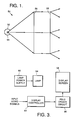
- FIG. 1 is a schematic diagram showing components of a display system embodying the invention.
- FIG. 2A illustrates an exemplary cell comprising the display screen of the system of FIG. 1, with the PDLC element in the non-scattering mode.
- FIG. 2B illustrate the exemplary cell with the PDLC element in the scattering mode.
- FIG. 3 is a block diagram of the display system of FIG. 1.
- FIG. 4 shows the desired scatter distribution when the PDLC element is fully scattering.
- FIG. 5 shows the scatter distribution when the PDLC is partially scattering, i.e., when the voltage applied to the PDLC is less than the maximum (minimum).
- a lamp is used simply as a light source to illuminate a display screen, which is a matrix of tiny cells that modulate the light at video rates.
- Each cell includes an electrically activated light scattering element, such as polymer dispersed liquid crystal (PDLC) material, a focusing lens and a pinhole aperture.
- PDLC polymer dispersed liquid crystal
- the PDLC is electrically activated, light passing through the PDLC is scattered in many directions, and very little light passes through the pinhole aperture and is seen by the viewer.
- the PDLC is not electrically activated, light passing through the PDLC is not scattered.
- the lens of each cell focuses the light through the pinhole aperture and the viewer sees a bright spot of light.
- FIG. 1 shows a display system 50 embodying the invention.
- a reflector 52 surrounding most of the lamp 54 directs the light toward a collimator 56, which collimates the light from the lamp 54 into a beam directed onto a screen 58.
- a xenon lamp preferably one having a small spherical luminous area on the order of 0.5-1 mm, is suitable for the lamp 54.
- a metal halide lamp could also be used; however, the luminous area is larger (2-8 mm)).
- the size of the pinhole is a function of the size of the luminous area of the lamp 54. The larger the luminous area, the larger the pinhole must be. The larger the pinhole, the more scattered light that escapes through the pinhole and, hence, the contrast ratio will be lower. Also, more ambient light will enter the larger pinhole and it will be reflected back to the viewer. If the luminous area of the lamp is elongated or tubular, the pinhole will also be elongated or tubular.
- Preferred collimators suitable for the purpose include Fresnel, kinoform, binary optic or diffractive/holographic collimators. It should be noted that use of a collimator is optional in the practice of this invention. The benefit of the collimator is that all cells in the screen matrix are identical if a collimator is used.
- the lens spacing between lens in adjacent cells comprising the screen can be constant, and the spacing of the pinholes should increase from the center of the screen to the perimeter. Conversely, the pinhole spacing can be constant while the lens spacing decreases from the center of the screen to the perimeter.
- the angle that the light enters each lens is a function of the lens location. The angle is zero degrees at the center of the screen. The angle increases with increasing distance from the center of the screen. Light that enters a lens at an angle other than zero degrees will focus to a point that is located some distance from the optical axis of the lens. Only light that enters the lens at zero degrees angle focuses on the optical axis. The pinhole should be placed at the focus point of the lens.
- the screen 58 is a matrix of tiny cells.
- FIGS. 2A and 2B illustrate the operation of one exemplary cell 60 comprising the screen 58.
- Each cell 60 has three components in this embodiment, an electrically activated light scattering element, in this embodiment a polymer dispersed liquid crystal (PDLC) 62, a focusing microlens 64, and a pinhole aperture 66 in an opaque (preferably black) surface 68.
- PDLC polymer dispersed liquid crystal
- the colliminated light from the lamp 54 is passed through lens 64, which focuses the light to a point at the pinhole 66, and the light passes through the pinhole 66 and is seen by the viewer.
- the diameter of the point is a function of the size of the luminous area of lamp 54, the focal length of the collimator 56, the focal length of the microlens 64 and the wavelength of the light.
- the area of the pinhole 66 is typically less than 1% as large as the cell area of the opaque surface 68. Thus, if the opaque surface is painted black, very little ambient light is reflected back toward the viewer.
- the PDLC 62 When the PDLC 62 is in the scattering state, as illustrated in FIG. 2B, light is scattered in many directions. Most of the light is blocked by the opaque surface 68. Very little light passes through the pinhole 66.
- the design goal in this exemplary application is to allow less than 1% of the light to pass through the pinhole 66 when the PDLC 62 is in the scattering state. Therefore, the contrast ratio of the display will be approximately 100:1.
- FIG. 3 is a block diagram of electrically operated elements of the display system 50.
- the lamp 54 is powered by a lamp power supply 80.
- the cells of the display screen 58 are electrically actuated by a PDLC driver circuit 86, under control of the display controller 90.
- the controller 90 acts in response to input video signals to actuate the matrix of cells to display the image defined by the input video signals.
- Driver circuits for PDLC materials are well known in the art. Such driver circuits conventionally include a transistor and capacitor located at each cell, and an X-Y grid of electrodes used to electrically activate the transistor by storing a charge on the capacitor. The amount of charge that is placed on the capacitor affects the degree that the transistor is "turned on.” If the transistor is fully turned on, the PDLC is subjected to maximum electric field and becomes fully scattering. If the transistor is not turned on, the PDLC is subjected to minimum electric field and does not scatter.
- the X-Y grid is silk screened onto a plastic sheet, such as a Mylar sheet.
- the transistors and capacitors are wire bonded onto the X-Y grid.
- the lens and pinhole array can be made by injection molding. The Mylar sheet and lens/pinhole array will be laminated together to form the finished screen.
- PDLCs There are various kinds of PDLCs. Some scatter light when excited by electrical voltage. Some scatter light when electrical voltage is removed. Either type can be used in the practice of this invention.
- each cell 60 will be .288 x .288 inches. This size of the cell 60 will provide eye limiting resolution at a viewing distance of 82.5 feet or greater. The total number of cells will be 187,500.
- the focal length of the lens 64 is a function of the desired viewing angle. For a viewing angle of +/- 30 degrees, the focal length of the lens will be .2494 inches, for this example.
- the microlens 64 is simply a small lens. The preferred manner of constructing the lens is injection molding.
- each cell in this exemplary 9 x 12 foot screen will be .096 x .288 inches.
- the viewing angle in the vertical direction will be +/- 10.9 degrees.
- the total number of cells will be 562,500.
- the color display system increases the number of cells by a factor of three for the same resolution, with one sub-cell for red, one sub-cell for green, and one sub-cell for blue.
- filters could be used to ensure that the respective sub-cells pass only the desired light color, using a filter is inefficient. Two-thirds of the light is absorbed/reflected by the filter. It is preferred to use a prism (or hologram) preceding each cell to spread the light into a spectrum so that the red light passes through the red cell, the green light passes through the green cell and the blue light passes through the blue cell.
- FIG. 4 shows the desired scatter distribution when the PDLC 62 is fully scattering.
- FIG. 5 shows the scatter distribution when the PDLC 62 is partially scattering.
- the voltage applied to the PDLC is less than maximum (minimum). This is how grey scale is obtained.
- the applied voltage changes the scatter distribution (angle) which affects the percentage of light that passes through the pinhole.
Landscapes
- Engineering & Computer Science (AREA)
- Multimedia (AREA)
- Signal Processing (AREA)
- Physics & Mathematics (AREA)
- General Physics & Mathematics (AREA)
- Chemical & Material Sciences (AREA)
- Crystallography & Structural Chemistry (AREA)
- Liquid Crystal (AREA)
- Projection Apparatus (AREA)
- Transforming Electric Information Into Light Information (AREA)
Applications Claiming Priority (2)
| Application Number | Priority Date | Filing Date | Title |
|---|---|---|---|
| US261520 | 1994-06-17 | ||
| US08/261,520 US5546202A (en) | 1994-06-17 | 1994-06-17 | Rear projection screen for high ambient light environments having a pinhole area substantially equal to luminous area of the light source |
Publications (2)
| Publication Number | Publication Date |
|---|---|
| EP0687943A2 true EP0687943A2 (fr) | 1995-12-20 |
| EP0687943A3 EP0687943A3 (fr) | 1997-03-05 |
Family
ID=22993679
Family Applications (1)
| Application Number | Title | Priority Date | Filing Date |
|---|---|---|---|
| EP95303518A Withdrawn EP0687943A3 (fr) | 1994-06-17 | 1995-05-24 | Ecran de projection par transparence pour des conditions de lumière ambiante élevées |
Country Status (6)
| Country | Link |
|---|---|
| US (1) | US5546202A (fr) |
| EP (1) | EP0687943A3 (fr) |
| JP (1) | JP2802050B2 (fr) |
| KR (1) | KR960003367A (fr) |
| CA (1) | CA2149552C (fr) |
| IL (1) | IL113759A (fr) |
Families Citing this family (7)
| Publication number | Priority date | Publication date | Assignee | Title |
|---|---|---|---|---|
| US5610735A (en) * | 1993-06-04 | 1997-03-11 | Matsushita Electric Industrial Co., Ltd. | Light scattering light valve projection apparatus |
| GB9409707D0 (en) * | 1994-05-14 | 1994-07-06 | Philips Electronics Uk Ltd | Liquid crystal projection display systems |
| JPH0950081A (ja) * | 1995-08-08 | 1997-02-18 | Sony Corp | 透過型表示装置 |
| US6814443B2 (en) | 2001-09-26 | 2004-11-09 | Digital Advertising Network Inc | Image projection system and its method of use |
| US20070247715A1 (en) * | 2006-04-21 | 2007-10-25 | Melvin Francis | Projection illumination systems lenses with diffractive optical elements |
| WO2007115664A1 (fr) * | 2006-04-06 | 2007-10-18 | Oc Oerlikon Balzers Ag | Système de projection et d'éclairage dans lequel sont utilisées des lentilles avec eléments optiques diffractifs |
| CN108351546B (zh) | 2015-06-30 | 2024-09-10 | 哥兹有限公司 | 用于显示投影屏幕的改进的聚合物分散液晶(pdlc) |
Citations (1)
| Publication number | Priority date | Publication date | Assignee | Title |
|---|---|---|---|---|
| EP0421855A1 (fr) * | 1989-10-03 | 1991-04-10 | Thomson-Csf | Système optique de reproduction d'images vidéo en couleurs |
Family Cites Families (20)
| Publication number | Priority date | Publication date | Assignee | Title |
|---|---|---|---|---|
| US2738706A (en) * | 1952-04-04 | 1956-03-20 | Jr Harvey A Thompson | Back-lighted projection screens |
| US3191495A (en) * | 1963-03-14 | 1965-06-29 | Wendell S Miller | Projection screen |
| US3523717A (en) * | 1967-02-01 | 1970-08-11 | Gen Electric | Composite back projection screen |
| JPS5251538Y2 (fr) * | 1972-04-25 | 1977-11-22 | ||
| DE2511390C2 (de) * | 1975-03-15 | 1984-03-15 | Agfa-Gevaert Ag, 5090 Leverkusen | Verfahren und Vorrichtung zur Herstellung von Tageslichtprojektionsschirmen sowie nach diesem Verfahren hergestellter Tageslichtprojektionsschirm |
| US4003080A (en) * | 1975-06-02 | 1977-01-11 | Laser Video, Inc. | Large screen video display systems and methods therefor |
| JPS5564228A (en) * | 1978-11-08 | 1980-05-14 | Mitsubishi Electric Corp | Reflection type projecting screen |
| US4613207A (en) * | 1984-05-08 | 1986-09-23 | Manchester R & D Partnership | Liquid crystal projector and method |
| AU4117585A (en) * | 1984-03-19 | 1985-10-11 | Kent State University | Light modulating material comprising a liquid crystal dispersion in a synthetic resin matrix |
| NL8503526A (nl) * | 1985-12-20 | 1987-07-16 | Philips Nv | Doorzichtprojektiescherm. |
| NL8600184A (nl) * | 1986-01-28 | 1987-08-17 | Philips Nv | Doorzichtprojektiesysteem. |
| US4964695A (en) * | 1987-10-06 | 1990-10-23 | North American Philips Corporation | Lenticular arrays for front projection screens and contrast improving method and device |
| JPH0387722A (ja) * | 1989-08-31 | 1991-04-12 | Asahi Glass Co Ltd | 背面投射型液晶表示装置 |
| JPH03126982A (ja) * | 1989-10-13 | 1991-05-30 | Omron Corp | 表示装置 |
| JPH07107594B2 (ja) * | 1990-02-26 | 1995-11-15 | シャープ株式会社 | 投影型画像表示装置 |
| DE69132253T2 (de) * | 1990-11-28 | 2001-01-04 | Canon K.K., Tokio/Tokyo | Lichtstreuende Flüssigkristallvorrichtung |
| JPH05196925A (ja) * | 1991-04-17 | 1993-08-06 | Asahi Glass Co Ltd | 投射型液晶表示装置 |
| JP2849492B2 (ja) * | 1991-05-31 | 1999-01-20 | シャープ株式会社 | 投影型液晶表示装置 |
| WO1993011452A1 (fr) * | 1991-11-25 | 1993-06-10 | Magnascreen Corporation | Systeme d'affichage a microprojection avec dispositif d'eclairage a fibre optique, et procede d'affichage et d'eclairage |
| JPH06167697A (ja) * | 1992-11-27 | 1994-06-14 | Teijin Ltd | 画像表示装置 |
-
1994
- 1994-06-17 US US08/261,520 patent/US5546202A/en not_active Expired - Lifetime
-
1995
- 1995-05-16 CA CA002149552A patent/CA2149552C/fr not_active Expired - Fee Related
- 1995-05-17 IL IL11375995A patent/IL113759A/xx not_active IP Right Cessation
- 1995-05-24 EP EP95303518A patent/EP0687943A3/fr not_active Withdrawn
- 1995-06-16 JP JP7150479A patent/JP2802050B2/ja not_active Expired - Fee Related
- 1995-06-16 KR KR1019950015964A patent/KR960003367A/ko not_active Ceased
Patent Citations (1)
| Publication number | Priority date | Publication date | Assignee | Title |
|---|---|---|---|---|
| EP0421855A1 (fr) * | 1989-10-03 | 1991-04-10 | Thomson-Csf | Système optique de reproduction d'images vidéo en couleurs |
Also Published As
| Publication number | Publication date |
|---|---|
| IL113759A0 (en) | 1995-08-31 |
| US5546202A (en) | 1996-08-13 |
| CA2149552C (fr) | 1999-02-23 |
| CA2149552A1 (fr) | 1995-12-18 |
| KR960003367A (ko) | 1996-01-26 |
| JPH08179261A (ja) | 1996-07-12 |
| EP0687943A3 (fr) | 1997-03-05 |
| JP2802050B2 (ja) | 1998-09-21 |
| IL113759A (en) | 1999-04-11 |
Similar Documents
| Publication | Publication Date | Title |
|---|---|---|
| US5760849A (en) | Liquid crystal display device and liquid crystal projection display device including means for controlling direction of light beams | |
| US10261405B2 (en) | Projection displays | |
| US5517278A (en) | Viewfinder for video cameras | |
| KR0130057B1 (ko) | 투사형 액정 표시장치(Projection type inage display apparatus) | |
| JPH0756158A (ja) | 背面投影スクリーンを使用する平坦なパネル表示装置 | |
| US6351295B2 (en) | Projection type liquid crystal display device | |
| US5546202A (en) | Rear projection screen for high ambient light environments having a pinhole area substantially equal to luminous area of the light source | |
| US20060274287A1 (en) | Light source array for lcd applications | |
| KR930005545B1 (ko) | 피디엘씨 이미지모듈을 이용한 프로젝션 광학계 | |
| US6151086A (en) | Method and apparatus for controllably scattering light using birefringent liquid crystal | |
| CA2161840A1 (fr) | Restituteur d'images, du type a projetction | |
| JP3323231B2 (ja) | ビューファインダおよびそれを具備するカメラ | |
| US6917355B1 (en) | Display device for projector and method of making and using a display device | |
| JPH0792443A (ja) | ビューファインダおよびそれを用いたビデオカメラ | |
| JPH07193735A (ja) | ビューファインダおよびそれを用いたビデオカメラ | |
| HK1104354B (en) | High dynamic range display devices | |
| HK1112292A (en) | High dynamic range display devices | |
| HK1069212B (en) | High dynamic range display devices |
Legal Events
| Date | Code | Title | Description |
|---|---|---|---|
| PUAI | Public reference made under article 153(3) epc to a published international application that has entered the european phase |
Free format text: ORIGINAL CODE: 0009012 |
|
| AK | Designated contracting states |
Kind code of ref document: A2 Designated state(s): DE FR GB |
|
| PUAL | Search report despatched |
Free format text: ORIGINAL CODE: 0009013 |
|
| RHK1 | Main classification (correction) |
Ipc: H04N 9/31 |
|
| AK | Designated contracting states |
Kind code of ref document: A3 Designated state(s): DE FR GB |
|
| 17P | Request for examination filed |
Effective date: 19970811 |
|
| 17Q | First examination report despatched |
Effective date: 19970903 |
|
| RAP1 | Party data changed (applicant data changed or rights of an application transferred) |
Owner name: RAYTHEON COMPANY |
|
| STAA | Information on the status of an ep patent application or granted ep patent |
Free format text: STATUS: THE APPLICATION IS DEEMED TO BE WITHDRAWN |
|
| 18D | Application deemed to be withdrawn |
Effective date: 20000725 |