EP0687965A2 - Appareil chauffé au gaz - Google Patents
Appareil chauffé au gaz Download PDFInfo
- Publication number
- EP0687965A2 EP0687965A2 EP95108868A EP95108868A EP0687965A2 EP 0687965 A2 EP0687965 A2 EP 0687965A2 EP 95108868 A EP95108868 A EP 95108868A EP 95108868 A EP95108868 A EP 95108868A EP 0687965 A2 EP0687965 A2 EP 0687965A2
- Authority
- EP
- European Patent Office
- Prior art keywords
- gas
- safety
- signal
- consumer
- path
- Prior art date
- Legal status (The legal status is an assumption and is not a legal conclusion. Google has not performed a legal analysis and makes no representation as to the accuracy of the status listed.)
- Granted
Links
- 239000002241 glass-ceramic Substances 0.000 claims abstract description 10
- 238000010411 cooking Methods 0.000 claims abstract description 5
- 238000012544 monitoring process Methods 0.000 claims description 3
- 230000005855 radiation Effects 0.000 claims description 3
- 239000007789 gas Substances 0.000 description 17
- 238000010586 diagram Methods 0.000 description 3
- 238000010438 heat treatment Methods 0.000 description 3
- 230000015572 biosynthetic process Effects 0.000 description 2
- 239000003990 capacitor Substances 0.000 description 2
- 230000007257 malfunction Effects 0.000 description 2
- QVGXLLKOCUKJST-UHFFFAOYSA-N atomic oxygen Chemical compound [O] QVGXLLKOCUKJST-UHFFFAOYSA-N 0.000 description 1
- 238000010276 construction Methods 0.000 description 1
- 238000001816 cooling Methods 0.000 description 1
- 238000009499 grossing Methods 0.000 description 1
- 238000012806 monitoring device Methods 0.000 description 1
- 239000001301 oxygen Substances 0.000 description 1
- 229910052760 oxygen Inorganic materials 0.000 description 1
- 238000002360 preparation method Methods 0.000 description 1
Images

Classifications
-
- F—MECHANICAL ENGINEERING; LIGHTING; HEATING; WEAPONS; BLASTING
- F24—HEATING; RANGES; VENTILATING
- F24C—DOMESTIC STOVES OR RANGES ; DETAILS OF DOMESTIC STOVES OR RANGES, OF GENERAL APPLICATION
- F24C3/00—Stoves or ranges for gaseous fuels
- F24C3/12—Arrangement or mounting of control or safety devices
- F24C3/126—Arrangement or mounting of control or safety devices on ranges
-
- F—MECHANICAL ENGINEERING; LIGHTING; HEATING; WEAPONS; BLASTING
- F23—COMBUSTION APPARATUS; COMBUSTION PROCESSES
- F23N—REGULATING OR CONTROLLING COMBUSTION
- F23N5/00—Systems for controlling combustion
- F23N5/24—Preventing development of abnormal or undesired conditions, i.e. safety arrangements
- F23N5/242—Preventing development of abnormal or undesired conditions, i.e. safety arrangements using electronic means
-
- G—PHYSICS
- G05—CONTROLLING; REGULATING
- G05D—SYSTEMS FOR CONTROLLING OR REGULATING NON-ELECTRIC VARIABLES
- G05D23/00—Control of temperature
- G05D23/19—Control of temperature characterised by the use of electric means
- G05D23/1906—Control of temperature characterised by the use of electric means using an analogue comparing device
- G05D23/1909—Control of temperature characterised by the use of electric means using an analogue comparing device whose output amplitude can only take two discrete values
-
- F—MECHANICAL ENGINEERING; LIGHTING; HEATING; WEAPONS; BLASTING
- F23—COMBUSTION APPARATUS; COMBUSTION PROCESSES
- F23N—REGULATING OR CONTROLLING COMBUSTION
- F23N2223/00—Signal processing; Details thereof
- F23N2223/08—Microprocessor; Microcomputer
Definitions
- the invention relates to a gas-heated device, in particular a cooking apparatus with at least one glass ceramic hob, the device having a gas radiation burner, a safety relay and a solenoid valve monitored by the latter in the gas supply device, and an electrical control device for operating the device including two independent ones Has safety paths for monitoring safety-sensitive consumers, such as solenoid valves or burners.
- the invention is suitable for use in gas stoves, gas heating systems, gas boilers, but preferably in glass ceramic hobs with gas heating.
- Glass ceramic hobs can be heated electrically or with gas.
- gas heating special precautions are required for the safe operation of the cooking apparatus in order to avoid accidents caused by escaping gas as far as possible.
- the construction of a glass ceramic cooktop using gas radiation burners, solenoid valves, glow igniters and temperature monitoring devices is known and is not the subject of the present invention.
- the electronic control device for the operation of the burners, glow igniter and solenoid valves, temperature monitoring and the like must have two mutually independent safety paths in order to ensure the proper functioning of the electronics with regard to the control of the burners or solenoid valves.
- a signal of a predetermined frequency (such as 1 kHz) output from the microprocessor in the control device is checked for presence and fault tolerance and component failure by an intrinsically safe circuit.
- the second safety path contains the switch of the safety relay which is closed during normal operation, the consumer, a triac for actuating it and a measuring element for determining the current flow through this safety path.
- a triac a relay or a transistor can in principle also be used as a controllable electrical switch in the sense of the invention.
- the safety relay is common to all solenoid valves
- the first and second safety path can either be individually assigned to each consumer (hob) or - preferably - the first safety path can be common to all consumers, while the second safety path can be separate for each consumer.
- the invention is further developed with regard to the formation of the first security path in such a way that an AND gate is used to check the presence and a bandpass filter is used to check the frequency tolerance of the signal.
- the AND element should generally mean an AND logic function.
- the invention can be developed in such a way that the measuring element is an ohmic resistor (shunt resistor), at which the presence of a voltage drop is determined.
- the measuring element is an ohmic resistor (shunt resistor), at which the presence of a voltage drop is determined.
- the essential component in the electronic control device is a microprocessor 1, which controls the operation of all devices in the glass ceramic cooktop. Its failure is therefore important to check. It is also important to check that the solenoid valves or gas burners are switched on. If there is no proper function, the gas supply must be switched off immediately.
- the microprocessor 1 is followed by an AND gate 2, the input of which has a microprocessor frequency, in the present case 1 kHz.
- An overvoltage signal from a power supply unit 3 is present at the other input of the AND gate 2, the latter ensuring the power supply of the electronic control device.
- the output signal of the power supply 3 is negated by an inverter 4.
- the first security path 5 contains a bandpass filter 6, a amplifier circuit 7, which is intrinsically safe, and a safety relay 8 with its associated switch contact 9.
- This switch contact 9 is part of a circuit 10, which is controlled by the second safety path 11.
- Part of the circuit 10 is a solenoid valve 12 or alternatively a gas burner, ie generally speaking, a safety-sensitive consumer.
- the second safety path 11 contains a triac 13 and a measuring resistor 14.
- the triac under the control of the microprocessor 1, is used to switch through the circuit 10 when the solenoid valve or the gas burner supplies power, i.e. to be put into operation.
- the measuring resistor 14 serves to determine whether a current is flowing in the circuit 10 or not.
- a malfunction indicator 15 is finally connected to the microprocessor 1, which can be designed as a lamp or acoustic signal generator or as a display.
- the mode of operation of the control device according to FIG. 1 is as follows.
- the microprocessor 1 When operating correctly, the microprocessor 1 outputs a square-wave signal with a frequency of 1 kHz to the AND gate 2.
- the power supply unit does not emit an overvoltage signal in normal operation, a signal is generated at the output of the inverter 4, which, together with the 1 kHz signal at the other input of the AND gate, switches it through at a clock rate of 1 kHz.
- the downstream band pass 6 which is a commercially available component and is therefore not described in more detail here, both the presence of a 1 kHz signal and compliance with an error tolerance of 10% are ascertained for this signal.
- the output signal at the amplifier 7 is a DC voltage signal.
- the microprocessor 1 when it receives the command from the outside that a cooktop is to be heated, gives a switching pulse to the triac 13 which switches the circuit 10 through in order to energize the solenoid valve 12 - or a gas burner.
- the switch contact 9 When the control device is operating properly, the switch contact 9 is already closed in preparation, so that in this case current flows through the solenoid valve when the triac 13 is switched through.
- the microprocessor In the event of an error, for example if the microprocessor is not working properly, it can be assumed that the 1 kHz signal is not present or is not present properly. In this case, the AND gate 2 is not switched through, the signal at its output disappears, there are no signals at the output of the bandpass 6 and the amplifier 7, the signal on line 16 thus disappears and the microprocessor receives feedback. The processing of this signal must be such that the microprocessor can also operate the fault display 15 in the event of an error. Regardless, is because the de-energization of the safety relay 8, the switch contact 9 has dropped and the circuit 10 has been opened. The solenoid valve - or the gas burner - receives no more current, the gas flow is interrupted. The same function results if the power supply unit 3 emits an overvoltage. In this case, a signal is output, which is negated in the inverter 4, whereby the signal at the input of the AND gate 2 disappears.
- Another error can be that the triac 13 switches through and, because the switch contact 9 is closed, a current flows in the circuit 10, although the triac 13 has not received a control signal.
- the measuring resistor 14 determines the current flow
- the microprocessor 1 recognizes that a current flows in the circuit 10 without a corresponding command. In this case, it switches off the 1 kHz signal and simultaneously sends a signal to the fault display.
- the microprocessor 1 Checking the failure of the microprocessor 1 is also important because it also controls a fan wheel, not shown in the drawing, which serves in the cooking apparatus for cooling and supplying oxygen to the burners. Even if this fan wheel does not rotate properly, be it because the microprocessor is faulty or because its speed does not have the required values due to other interferences, the 1 kHz signal is switched off by the microprocessor and the fault indicator 15 is switched on.
- FIG. 7 A possible embodiment of the amplifier circuit 7 is shown in FIG. Via an input transistor 21, the incoming square-wave signal is amplified via push-pull amplifiers 22a and 22b and passed to a rectifier bridge 24 via filter capacitors 23. The latter is followed by a smoothing capacitor 25 and the safety relay 8 already described. If the signal at transistor 21 disappears, the voltage at the output of rectifier bridge 24 and thus at safety relay 8 also disappears. If one of the components of this circuit according to FIG. 2 fails, the voltage disappears at the output of the rectifier bridge 24 with the sequence just described for the safety relay 8.
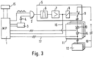
- FIG. 3 the possibility is shown in a block diagram of controlling several, in this case 3, glass ceramic cooktops 12.
- the security path 5 is provided once, the security path 5 is provided once, the security path 11 is tripled.
- the corresponding lines, which also exist several times, are identified by a corresponding number of dashes.
- the principle of operation of the circuit arrangement corresponds to that of FIG. 1.
Landscapes
- Engineering & Computer Science (AREA)
- Chemical & Material Sciences (AREA)
- Combustion & Propulsion (AREA)
- Mechanical Engineering (AREA)
- General Engineering & Computer Science (AREA)
- Physics & Mathematics (AREA)
- General Physics & Mathematics (AREA)
- Automation & Control Theory (AREA)
- Regulation And Control Of Combustion (AREA)
Applications Claiming Priority (2)
| Application Number | Priority Date | Filing Date | Title |
|---|---|---|---|
| DE4421361A DE4421361A1 (de) | 1994-06-18 | 1994-06-18 | Gasbeheiztes Gerät |
| DE4421361 | 1994-06-18 |
Publications (3)
| Publication Number | Publication Date |
|---|---|
| EP0687965A2 true EP0687965A2 (fr) | 1995-12-20 |
| EP0687965A3 EP0687965A3 (fr) | 1996-04-03 |
| EP0687965B1 EP0687965B1 (fr) | 1999-09-08 |
Family
ID=6520924
Family Applications (1)
| Application Number | Title | Priority Date | Filing Date |
|---|---|---|---|
| EP95108868A Expired - Lifetime EP0687965B1 (fr) | 1994-06-18 | 1995-06-08 | Appareil chauffé au gaz |
Country Status (5)
| Country | Link |
|---|---|
| US (1) | US5673680A (fr) |
| EP (1) | EP0687965B1 (fr) |
| AU (1) | AU696614B2 (fr) |
| BR (1) | BR9502817A (fr) |
| DE (2) | DE4421361A1 (fr) |
Families Citing this family (7)
| Publication number | Priority date | Publication date | Assignee | Title |
|---|---|---|---|---|
| IT1313950B1 (it) * | 1999-12-16 | 2002-09-26 | Whirlpool Co | Dispositivo per ottenere la rapida accensione di un bruciatore a gasdi un piano di cottura alimentato attraverso un condotto del gas |
| DE10163197A1 (de) * | 2001-12-21 | 2003-07-03 | Bsh Bosch Siemens Hausgeraete | Verfahren zur Überprüfung der elektrischen Sicherheit eines Haushaltgeräts und entsprechendes Haushaltgerät |
| US7467639B2 (en) * | 2003-03-28 | 2008-12-23 | General Electric Company | Systems and methods for controlling gas flow |
| DE102004013971B4 (de) * | 2004-03-19 | 2008-07-17 | Rational Ag | Brennereinrichtung für ein Gargerät und Gargerät mit solch einer Brennereinrichtung |
| US20090241935A1 (en) * | 2008-03-26 | 2009-10-01 | Athir Jaaz | Gas cooking appliance |
| US10655891B2 (en) * | 2017-12-14 | 2020-05-19 | Emerson Electric Co. | Gas valve control system for a water heater |
| JP6950564B2 (ja) * | 2018-02-19 | 2021-10-13 | 株式会社ノーリツ | 燃焼装置 |
Family Cites Families (10)
| Publication number | Priority date | Publication date | Assignee | Title |
|---|---|---|---|---|
| DE1529070C3 (de) * | 1966-07-28 | 1979-06-07 | Imperial-Werke Gmbh, 4980 Buende | Einrichtung zur Offenhaltung von Gassicherheitsschaltern zugeordneten Gasventilen bei Gasbrennern mit thermoelektrischer Sicherung |
| DE2700025A1 (de) * | 1977-01-03 | 1978-07-13 | Jenaer Glaswerk Schott & Gen | Steuerungs- und ueberwachungssystem fuer gasstrahlungsbrenner zur beheizung von glaskeramik-kochflaechen |
| JPS5743135A (en) * | 1980-08-29 | 1982-03-11 | Matsushita Electric Ind Co Ltd | High frequency heating device |
| US4663710A (en) * | 1981-05-15 | 1987-05-05 | The Frymaster Corporation | Intelligent cooking appliance |
| DE3815984A1 (de) * | 1988-05-10 | 1989-11-23 | Diehl Gmbh & Co | Sicherheitsschaltung fuer einen elektrischen kochherd |
| ATE111587T1 (de) * | 1988-07-20 | 1994-09-15 | Vaillant Gmbh | Verfahren zum steuern und überwachen eines brennstoffbeheizten gerätes unter verwendung zumindest eines mikrocomputersystems und vorrichtung zur durchführung des verfahrens. |
| DE3844082A1 (de) * | 1988-12-28 | 1990-07-05 | Cramer Gmbh & Co Kg | Kochapparat mit zumindest einem glaskeramik-kochfeld |
| DE59007264D1 (de) * | 1990-02-06 | 1994-10-27 | Honeywell Bv | Zünd- und Sicherheitsschaltung für Gasbrenner. |
| DE4003799C1 (fr) * | 1990-02-08 | 1991-04-18 | Cramer Gmbh & Co Kg, 5750 Menden, De | |
| US5575638A (en) * | 1994-03-29 | 1996-11-19 | Thermador Corporation | Stove burner simmer control |
-
1994
- 1994-06-18 DE DE4421361A patent/DE4421361A1/de not_active Withdrawn
-
1995
- 1995-06-08 EP EP95108868A patent/EP0687965B1/fr not_active Expired - Lifetime
- 1995-06-08 DE DE59506758T patent/DE59506758D1/de not_active Expired - Fee Related
- 1995-06-14 BR BR9502817A patent/BR9502817A/pt not_active Application Discontinuation
- 1995-06-15 US US08/490,835 patent/US5673680A/en not_active Expired - Fee Related
- 1995-06-16 AU AU21732/95A patent/AU696614B2/en not_active Ceased
Also Published As
| Publication number | Publication date |
|---|---|
| EP0687965A3 (fr) | 1996-04-03 |
| US5673680A (en) | 1997-10-07 |
| AU696614B2 (en) | 1998-09-17 |
| AU2173295A (en) | 1996-01-04 |
| BR9502817A (pt) | 1996-02-27 |
| DE4421361A1 (de) | 1995-12-21 |
| EP0687965B1 (fr) | 1999-09-08 |
| DE59506758D1 (de) | 1999-10-14 |
Similar Documents
| Publication | Publication Date | Title |
|---|---|---|
| DE3880772T2 (de) | Flammendetektorsignal-verarbeitungssystem. | |
| DE2444455C3 (de) | Steuersystem für eine Brenneranlage | |
| DE102005055325B3 (de) | Sicherheitsschaltvorrichtung zum fehlersicheren Abschalten eines elektrischen Verbrauchers | |
| EP0687965B1 (fr) | Appareil chauffé au gaz | |
| DE10351873B4 (de) | Vorrichtung und Verfahren zum fehlersicheren Abschalten eines induktiven Verbrauchers | |
| EP0525345B1 (fr) | Dispositif et procédé de surveillance d'une flamme | |
| DE3101747C2 (fr) | ||
| DE1551954A1 (de) | Steuereinrichtung fuer eine Feuerungsanlage | |
| DE1673960A1 (de) | Schaltungsanordnung zur UEberwachung eines physikalischen Zustandes | |
| EP1843645B1 (fr) | Circuit pour lampes à décharge haute pression | |
| DE2222258B1 (de) | Steuerschaltung fuer eine brenneranlage | |
| EP1081431B1 (fr) | Appareil de commande pour installations thermiques | |
| DE2809993B2 (de) | Flammenwächterschaltung zur Überwachung einer Brennerflamme | |
| EP0855557B1 (fr) | Circuit de commande d'une soupape à gaz avec contrÔle de l'alimentation d'air comburant | |
| EP3106753B1 (fr) | Surveillance de flammes | |
| EP3742466A1 (fr) | Ensemble de circuit permettant de commuter de manière sécurisée un consommateur électrique selon une mesure de sécurité | |
| EP0470043B1 (fr) | Dispositif circuit électrique | |
| DE2733798C3 (de) | Verfahren und Anordnung zur Rotlampenüberwachung von Signalgebern | |
| DE19504473C2 (de) | Sicherheitsschaltung für eine Kochmuldenelektronik | |
| DE3532017A1 (de) | Sicherheitsschaltung zum steuern kritischer lasten von gas- oder oelbrennern | |
| AT400755B (de) | Einrichtung zur ansteuerung eines feuerungsautomaten | |
| EP0315055A1 (fr) | Méthode pour vérifier une soupape à gaz et dispositif de réalisation de la méthode | |
| DE19752323C1 (de) | Wechselstromgespeiste Steuerschaltung für Gasmagnetventile | |
| DE102007002060A1 (de) | Vorrichtung zum Schalten eines Kochfeldes und Verfahren zum Beurteilen eines fehlerhaften Betriebs eines Kochfeldes | |
| AT396636B (de) | Einrichtung zur ansteuerung |
Legal Events
| Date | Code | Title | Description |
|---|---|---|---|
| PUAI | Public reference made under article 153(3) epc to a published international application that has entered the european phase |
Free format text: ORIGINAL CODE: 0009012 |
|
| AK | Designated contracting states |
Kind code of ref document: A2 Designated state(s): DE ES FR GB IT NL |
|
| PUAL | Search report despatched |
Free format text: ORIGINAL CODE: 0009013 |
|
| AK | Designated contracting states |
Kind code of ref document: A3 Designated state(s): DE ES FR GB IT NL |
|
| 17P | Request for examination filed |
Effective date: 19960302 |
|
| 17Q | First examination report despatched |
Effective date: 19971209 |
|
| RAP1 | Party data changed (applicant data changed or rights of an application transferred) |
Owner name: DIEHL STIFTUNG & CO. |
|
| GRAG | Despatch of communication of intention to grant |
Free format text: ORIGINAL CODE: EPIDOS AGRA |
|
| GRAG | Despatch of communication of intention to grant |
Free format text: ORIGINAL CODE: EPIDOS AGRA |
|
| GRAH | Despatch of communication of intention to grant a patent |
Free format text: ORIGINAL CODE: EPIDOS IGRA |
|
| GRAH | Despatch of communication of intention to grant a patent |
Free format text: ORIGINAL CODE: EPIDOS IGRA |
|
| GRAA | (expected) grant |
Free format text: ORIGINAL CODE: 0009210 |
|
| AK | Designated contracting states |
Kind code of ref document: B1 Designated state(s): DE ES FR GB IT NL |
|
| PG25 | Lapsed in a contracting state [announced via postgrant information from national office to epo] |
Ref country code: IT Free format text: LAPSE BECAUSE OF FAILURE TO SUBMIT A TRANSLATION OF THE DESCRIPTION OR TO PAY THE FEE WITHIN THE PRE;WARNING: LAPSES OF ITALIAN PATENTS WITH EFFECTIVE DATE BEFORE 2007 MAY HAVE OCCURRED AT ANY TIME BEFORE 2007. THE CORRECT EFFECTIVE DATE MAY BE DIFFERENT FROM THE ONE RECORDED.SCRIBED TIME-LIMIT Effective date: 19990908 Ref country code: GB Free format text: LAPSE BECAUSE OF FAILURE TO SUBMIT A TRANSLATION OF THE DESCRIPTION OR TO PAY THE FEE WITHIN THE PRESCRIBED TIME-LIMIT Effective date: 19990908 Ref country code: FR Free format text: LAPSE BECAUSE OF FAILURE TO SUBMIT A TRANSLATION OF THE DESCRIPTION OR TO PAY THE FEE WITHIN THE PRESCRIBED TIME-LIMIT Effective date: 19990908 Ref country code: ES Free format text: THE PATENT HAS BEEN ANNULLED BY A DECISION OF A NATIONAL AUTHORITY Effective date: 19990908 |
|
| REF | Corresponds to: |
Ref document number: 59506758 Country of ref document: DE Date of ref document: 19991014 |
|
| EN | Fr: translation not filed | ||
| GBV | Gb: ep patent (uk) treated as always having been void in accordance with gb section 77(7)/1977 [no translation filed] |
Effective date: 19990908 |
|
| PLBE | No opposition filed within time limit |
Free format text: ORIGINAL CODE: 0009261 |
|
| STAA | Information on the status of an ep patent application or granted ep patent |
Free format text: STATUS: NO OPPOSITION FILED WITHIN TIME LIMIT |
|
| 26N | No opposition filed | ||
| PGFP | Annual fee paid to national office [announced via postgrant information from national office to epo] |
Ref country code: NL Payment date: 20010630 Year of fee payment: 7 |
|
| PGFP | Annual fee paid to national office [announced via postgrant information from national office to epo] |
Ref country code: DE Payment date: 20010822 Year of fee payment: 7 |
|
| PG25 | Lapsed in a contracting state [announced via postgrant information from national office to epo] |
Ref country code: NL Free format text: LAPSE BECAUSE OF NON-PAYMENT OF DUE FEES Effective date: 20030101 Ref country code: DE Free format text: LAPSE BECAUSE OF NON-PAYMENT OF DUE FEES Effective date: 20030101 |
|
| NLV4 | Nl: lapsed or anulled due to non-payment of the annual fee |
Effective date: 20030101 |