EP0688084A2 - Système de charge pour un véhicule - Google Patents
Système de charge pour un véhicule Download PDFInfo
- Publication number
- EP0688084A2 EP0688084A2 EP95108999A EP95108999A EP0688084A2 EP 0688084 A2 EP0688084 A2 EP 0688084A2 EP 95108999 A EP95108999 A EP 95108999A EP 95108999 A EP95108999 A EP 95108999A EP 0688084 A2 EP0688084 A2 EP 0688084A2
- Authority
- EP
- European Patent Office
- Prior art keywords
- additional
- generator
- wiring
- battery
- controller
- Prior art date
- Legal status (The legal status is an assumption and is not a legal conclusion. Google has not performed a legal analysis and makes no representation as to the accuracy of the status listed.)
- Withdrawn
Links
Images
Classifications
-
- H—ELECTRICITY
- H02—GENERATION; CONVERSION OR DISTRIBUTION OF ELECTRIC POWER
- H02J—ELECTRIC POWER NETWORKS; CIRCUIT ARRANGEMENTS OR SYSTEMS FOR SUPPLYING OR DISTRIBUTING ELECTRIC POWER; SYSTEMS FOR STORING ELECTRIC ENERGY
- H02J7/00—Circuit arrangements for charging or discharging batteries or for supplying loads from batteries
- H02J7/14—Circuit arrangements for charging or discharging batteries or for supplying loads from batteries for charging batteries from dynamo-electric generators driven at varying speed, e.g. on vehicle
- H02J7/1423—Circuit arrangements for charging or discharging batteries or for supplying loads from batteries for charging batteries from dynamo-electric generators driven at varying speed, e.g. on vehicle with multiple batteries
Definitions
- the invention relates to a charging current system for a vehicle, in particular a commercial vehicle, having a battery, an internal combustion engine, a generator, a regulator for the generator and with a wiring which connects the generator to the battery and to the regulator.
- Vehicles such as commercial vehicles or work vehicles, for example tractors, have a charging current system which is provided for charging the battery and for generating electricity during operation.
- Such charging current systems are characterized by the generator power, and as a rule a generator is selected which performs 10 to 20% more than is necessary at full load.
- High generator outputs can also be required if additional consumers are installed that were not intended by the manufacturer or if closed generators have to be used in the presence of a lot of moisture and dirt.
- high temperatures around the generator can lead to great heat development in the generator and thus to a drop in performance.
- the generator is not operated at too high a speed because this could generate a voltage that would damage the controller.
- the originally intended generator can be replaced by one with a higher output, but this also requires the wiring to be reinforced. In addition, such a replacement is costly and time-consuming.
- the invention therefore provides that the wiring has a first wiring section and a second wiring section, which can be connected to one another via a plug connector with a first and a second plug part, and that an additional charging current system is provided which connects one from the internal combustion engine driven additional generator having an output and an additional wiring connected to the additional generator with a third and a fourth connector part, the third and fourth connector part can be plugged into the connector when the first and the second connector part are separated. In this way, the additional system is integrated into the original system.
- the total capacity of the system can easily be increased and, for example, if one subsystem fails, the other can maintain its function. Only minor interventions need to be carried out in the originally intended charging circuit. To increase the capacity, only the plug connector needs to be disconnected and connected to the plug parts of the additional wiring after the additional generator has been installed. If one system fails, the other system can take over the power supply.
- the additional wiring is designed such that the additional generator is connected in parallel or substantially in parallel with the generator when the third and fourth plug parts with the first and the second connector part are connected.
- the total capacity can be almost doubled and if one generator fails, the other can take over and the operation is not impaired too much.
- an electrical part such as a diode, can also be provided between the positive lines or the negative lines.
- the additional charging current system has an additional controller and that the controller and the additional controller have monitoring inputs and regulated outputs, the additional wiring having a line which connects the monitoring inputs. The last feature coordinates the voltage monitoring.
- the additional wiring can have two lines which connect the regulated outputs of the controllers to one another, the additional wiring having a common line connected to the controller and the additional controller.
- the power lines of the original system leading to the battery can in principle continue to be used.
- the additional wiring has a positive and a negative high-performance line, which are connected to the battery and create a current connection from the controller and the additional controller to the battery. It is therefore not necessary to reinforce the wiring of the original system.
- Another aspect of the invention provides that an auxiliary generator with an output which is driven from and connected to the internal combustion engine, and that additional wiring is provided which extends between the output of the auxiliary generator and the battery and the auxiliary generator in parallel or connects substantially parallel to the generator.
- This integrated system can also be easily retrofitted if the first wiring has a first and a second wiring section, which can be connected to one another via a plug connector with a first and a second plug part, and in that the additional wiring has a plug connection that is connected in the first and the second plug part is pluggable and connects the generator to the additional generator in parallel.
- the additional wiring has a positive and a negative line, which connects the output of the generator and the output of the additional generator to the battery, the plug connection being designed such that it has a line leading to the battery in the turns off the first wiring when the connector is connected to the first and to the second connector part.
- an additional controller is connected to the additional generator, the controller and the additional controller having monitoring inputs which are connected to one another and to the battery.
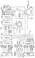
- an internal combustion engine 10 for a work vehicle which can be an agricultural tractor or also a small tractor that can be used in property maintenance, is only indicated.
- a conventional three-phase generator 12 is assigned to the motor 10 and supplies a battery 14 with wiring sections 20a and 20b via wiring. Further circuits lead from the battery to the consumers.
- the section 20a is provided with a plug part 22a with 6 cable connections and a corresponding number of contacts or contact pins, which can be plugged into a plug part 22b with a single generator in a charging circuit, which also has 6 cable connections with a corresponding number of contacts or contact sleeves.
- the connector parts 22a and 22b form a connector.
- the wiring section 20a is provided with two leads 24a and 26a connected to terminals 24 and 26 on the generator 12, a lead 28a connected to the output of an ignition switch 30, and a discharge indicator lead 32a provided with a terminal a discharge indicator 34 is connected.
- the input of the ignition switch 30 is connected to the positive terminal of the battery 14 and the other terminal of the discharge indicator 34 is connected to the negative terminal of the battery 14.
- Two further lines 36a and 38a of the wiring section 20a are still connected to the battery 14, namely the line 36a to the positive terminal and the line 38a to the negative terminal.
- the six lines of the wiring section 20b are designated 24b, 26b, 28b, 32b, 36b and 38b. These lines are connected to the input terminals of a regulator 42 for the generator 12.
- the lines 24b and 26b are input lines that come from the generator 12.
- Line 28b is a voltage monitor line that monitors the voltage on battery 14.
- Line 32b is a discharge indicator line and lines 36b and 38b are positive and negative output lines leading from controller 42 to battery 14.
- the plug part 22a of the wiring section 20a is inserted into the plug part 22b of the wiring section 20b, so that the Lines 24a, 26a, 28a, 32a, 36a and 38a are connected directly to lines 24b, 26b, 28b, 32b, 36b and 38b.
- the three-phase generator 12 generates a charging current flowing through the lines 36a, 36b and 38a, 38b up to a maximum strength, which can be in the range between 10A to 20A in typical work vehicles.
- another circuit or additional circuit for an additional three-phase generator is designated by 50.
- This is intended for systems that require high generator outputs for longer periods, possibly at low engine speeds.
- Such a circuit is used when a charging power is required which is higher than the generator power of the alternator 12, which can be the case, for example, when the current-carrying accessories and auxiliary devices each require up to 25 A or more. If this circuit 50 is now combined with the original charging circuit, a total charging capacity is obtained which is sufficient even with the engine idling in systems which require a high charging capacity.
- the additional circuit 50 is equipped with an additional three-phase generator or additional generator 52, which is likewise arranged on the internal combustion engine 10 and preferably with one Pulley 54 is equipped, which can be driven by a drive belt provided on the motor and driven by it, but not shown in the drawing, via a corresponding belt.
- the wiring of the additional circuit 50 is designated 60.
- Two generator lines 64a and 66a can be seen, which can be connected to terminals 64 and 66 on the additional generator 52 via a coupling element 68.
- the generator lines 64a and 66a lead to a further coupling element 70, which connects the generator lines 64a and 66a to input lines 64b and 66b, which belong to an additional regulator 72. In principle, this is identical to the controller 42.
- a voltage monitoring line 78b, a discharge indicator line 82b and a positive and a negative terminal line 86b and 88b are also provided.
- the wiring 50 of the additional circuit 50 also includes lines 78a, 82a, 86a and 88a, which via the further coupling element 70 to the voltage monitoring line 78b, the discharge indicator line 82b and to the positive and negative terminal lines 86b and 88b on the additional controller 72 keep in touch.
- the lines 78a, 82a are additionally connected to two plug parts 92a and 92b, while the lines 86a and 88a are only connected to the plug part 92a. If the plug parts 22a and 22b are not plugged into one another, the plug part 92a can be plugged into the plug part 22b and the plug part 92b into the plug part 22a, for which purpose corresponding contacts or contact pins or contact sleeves are provided on the plug parts 22a and 22b.
- the plug parts 92a and 92b of the additional circuit 50 are connected to one another via generator through lines 94 and 96, which connect the lines 24a and 24b of the wiring section 20a to the lines 24b and 26b of the wiring section 20b, and via a voltage monitoring line 98, to which the Line 82a is connected and which connects the line 32a of the wiring section 20a with the line 32b of the wiring section 20b, and still connected via a discharge indicator line 102 to which the line 82a is connected and which connects the line 32a of the wiring section 20a with the line 32a of the wiring section 20a with the line 32b of the wiring section 20b when the additional circuit 50 is switched on or when the plug parts 92a and 92b of the additional circuit 50 into the plug parts 22b and 22a of the original charging circuit composed of the wiring sections 20a and 20b are plugged.
- the auxiliary circuit 50 is switched on, the same voltage is thus monitored by the monitoring lines 28b and 78b. The same applies to the discharge indicator.
- lines 106 and 108 are connected to lines 86a and 88a, so that a high-performance connection is created between the outputs of the regulators and the positive and negative terminal of the battery 14, which connects the entire capacity of the alternators 12 and 52 processed, the total capacity essentially corresponds to the sum of the individual three-phase generators.
- lines 36a and 38a could also be designed as heavy-duty lines and corresponding connecting lines could be provided between plug parts 92a and 92b, as a result of which lines 106 and 108 could be omitted.
- a connection of the controllers to the battery via lines 106 and 108 is preferred, however, because they create a more reliable circuit and because the connector parts would also have to absorb the cumulative output current.
- the charging circuit it is possible to design the charging circuit to operate in a conventional manner.
- the additional circuit 50 is not required and the two plug parts 22a and 22b are plugged directly into one another.
- the power supply takes place exclusively via the generator 12.
- the auxiliary generator 52 is connected to the internal combustion engine 10 in a conventional manner and the auxiliary controller 72 is connected to the vehicle.
- the wiring 60 is installed by inserting the coupling members 68 and 70.
- the connector parts 22a and 22b are separated from each other, and the connector part 92a is inserted into the connector part 22b and the connector part 92b is inserted into the connector part 22a.
- lines 106 and 108 are to be connected to the positive and negative terminals of battery 14 and the additional system is installed.
- the combined charging current system allows the original charging circuit with its wiring sections 20a and 20b to be reused. By connecting the additional circuit, the total capacity can be increased in a simple manner if this becomes necessary.
- the additional circuit is easy to install and remove due to the provided connector parts and coupling elements in case of troubleshooting. If one circuit fails, the other circuit can maintain the functionality of the vehicle.
Landscapes
- Engineering & Computer Science (AREA)
- Power Engineering (AREA)
- Control Of Charge By Means Of Generators (AREA)
Applications Claiming Priority (2)
| Application Number | Priority Date | Filing Date | Title |
|---|---|---|---|
| US261521 | 1994-06-17 | ||
| US08/261,521 US5600232A (en) | 1994-06-17 | 1994-06-17 | Alternator system for a vehicle |
Publications (2)
| Publication Number | Publication Date |
|---|---|
| EP0688084A2 true EP0688084A2 (fr) | 1995-12-20 |
| EP0688084A3 EP0688084A3 (fr) | 1996-11-13 |
Family
ID=22993683
Family Applications (1)
| Application Number | Title | Priority Date | Filing Date |
|---|---|---|---|
| EP95108999A Withdrawn EP0688084A3 (fr) | 1994-06-17 | 1995-06-12 | Système de charge pour un véhicule |
Country Status (3)
| Country | Link |
|---|---|
| US (1) | US5600232A (fr) |
| EP (1) | EP0688084A3 (fr) |
| CA (1) | CA2140515C (fr) |
Families Citing this family (10)
| Publication number | Priority date | Publication date | Assignee | Title |
|---|---|---|---|---|
| US5739676A (en) * | 1996-11-04 | 1998-04-14 | Ford Motor Company | Multiple-alternator electrical system |
| US6369549B1 (en) | 1998-10-05 | 2002-04-09 | Ford Global Tech., Inc. | Motor vehicle electrical system with multiple generators |
| US6314918B1 (en) | 1999-06-10 | 2001-11-13 | Mcfarland Steve | Renewable fuel generating system |
| US7019495B2 (en) * | 2003-08-28 | 2006-03-28 | C.E. Neihoff & Co. | Inter-regulator control of multiple electric power sources |
| WO2005050332A2 (fr) * | 2003-11-17 | 2005-06-02 | Ballard Commercial Industries, Inc. | Systeme de regulateur ameliore pour alternateur |
| US7365519B2 (en) * | 2005-04-06 | 2008-04-29 | Basler Electric Company | Excitation system having inner loop voltage regulator with by-pass capability |
| US20090237038A1 (en) * | 2007-04-11 | 2009-09-24 | Ron Heidebrink | Double alternator and electrical system |
| US7291933B1 (en) * | 2007-04-11 | 2007-11-06 | Ron Heidebrink | Double alternator and electrical system for a vehicle |
| CN109154337B (zh) * | 2016-05-27 | 2021-06-29 | 卡明斯公司 | 包括多附件驱动装置的原动机系统及其控制方法 |
| JP6761398B2 (ja) * | 2017-09-20 | 2020-09-23 | 株式会社オートネットワーク技術研究所 | ワイヤーハーネス及びワイヤーハーネスの接続構造 |
Family Cites Families (12)
| Publication number | Priority date | Publication date | Assignee | Title |
|---|---|---|---|---|
| US3793544A (en) * | 1972-02-10 | 1974-02-19 | Caterpillar Tractor Co | Multiple winding, multiple voltage, alternator system |
| GB1596508A (en) * | 1976-12-18 | 1981-08-26 | Lucas Industries Ltd | Battery charging system for road vehicles |
| US4336485A (en) * | 1979-04-26 | 1982-06-22 | Stroud Lebern W | Dual alternator feedback system |
| US4347473A (en) * | 1979-04-26 | 1982-08-31 | Stroud Lebern W | Dual alternator power system for motor vehicle |
| US4567756A (en) * | 1984-03-23 | 1986-02-04 | Colborn Nicol S | Electronic engine control systems analyzer |
| EP0171737B1 (fr) * | 1984-08-07 | 1990-12-27 | Sumitomo Wiring Systems, Ltd. | Dispositif de connection pour le branchement de fils électriques |
| JPH0643175B2 (ja) * | 1986-08-22 | 1994-06-08 | マツダ株式会社 | 自動車の電動シ−ト装置 |
| US4842524A (en) * | 1987-11-03 | 1989-06-27 | Hopkins Manufacturing Corporation | Trailer light connection systems |
| US4829228A (en) * | 1988-05-06 | 1989-05-09 | General Motors Corporation | Dual generator electrical system |
| FR2675644B1 (fr) * | 1991-04-19 | 1993-08-27 | Valeo Equip Electr Moteur | Circuit electrique bi-tension a signalisation de defaut perfectionnee, notamment pour vehicule automobile. |
| FR2691021B1 (fr) * | 1992-05-07 | 1994-06-24 | Valeo Equip Electr Moteur | Dispositif d'alimentation electrique sous tension elevee d'un circuit auxiliaire d'un vehicule automobile. |
| US5254936A (en) * | 1992-09-14 | 1993-10-19 | General Motors Corporation | Dual generator electrical system |
-
1994
- 1994-06-17 US US08/261,521 patent/US5600232A/en not_active Expired - Lifetime
-
1995
- 1995-01-18 CA CA002140515A patent/CA2140515C/fr not_active Expired - Fee Related
- 1995-06-12 EP EP95108999A patent/EP0688084A3/fr not_active Withdrawn
Non-Patent Citations (1)
| Title |
|---|
| None |
Also Published As
| Publication number | Publication date |
|---|---|
| CA2140515A1 (fr) | 1995-12-18 |
| CA2140515C (fr) | 1997-01-14 |
| EP0688084A3 (fr) | 1996-11-13 |
| US5600232A (en) | 1997-02-04 |
Similar Documents
| Publication | Publication Date | Title |
|---|---|---|
| DE102008022776B4 (de) | Vereinfachte automatische Entladefunktion für Fahrzeuge | |
| EP0850506B1 (fr) | Dispositif d'alimentation en courant dans un vehicule automobile | |
| EP1593188B1 (fr) | Dispositif pour alimenter en energie un systeme electrique bitension d'un vehicule | |
| DE10326294B4 (de) | Stromversorgungssystem für ein Fahrzeug | |
| DE19855245B4 (de) | Redundante Spannungsversorgung für elektrische Verbraucher | |
| DE112017006219B4 (de) | Fahrzeugmontierte Energieversorgungsvorrichtung | |
| DE102009033185B4 (de) | Ladesystem und Ladeverfahren zum Laden einer Batterie eines Fahrzeugs und Fahrzeug mit einem solchen Ladesystem | |
| DE102019201068B4 (de) | Stromversorgungssystem | |
| DE4302809A1 (en) | Control of voltage drop in vehicle electrical supply - requires two separate batteries charged up in parallel, one for starter motor, one for remainder of circuit | |
| DE102005004330A1 (de) | Bordnetz für sicherheitsrelevante Verbraucher | |
| EP3022433A1 (fr) | Montage de contacteur dans un circuit de bord de véhicule à moteur | |
| DE102014105106A1 (de) | Intelligente Leistungsverteilungseinheit | |
| DE102020209673A1 (de) | Ladesäule zum Laden eines Stromspeichers eines Elektrofahrzeugs | |
| DE10236020A1 (de) | Energieverteileinrichtung | |
| WO2016113298A1 (fr) | Batterie haute tension destinée à un véhicule automobile et véhicule automobile | |
| EP0688084A2 (fr) | Système de charge pour un véhicule | |
| EP2877366A2 (fr) | Ensemble circuit électrique pour un véhicule électrique, véhicule et procédé correspondant | |
| DE10317362B4 (de) | Fahrzeugbordnetz und Verfahren zum Betreiben eines Fahrzeugbordnetzes | |
| DE2648372A1 (de) | Stromversorgungseinrichtung fuer eine zweispannungsanlage in einem kraftfahrzeug | |
| DE10301954A1 (de) | In einem Fahrzeug eingebaute elektrische Leistungsversorgungsvorrichtung | |
| DE102019209654A1 (de) | Fahrzeugbordnetz | |
| DE102006002985A1 (de) | Energiespeichersystem für ein Kraftfahrzeug | |
| DE112018004777T5 (de) | Verbindungseinheit und Stromversorgungssystem | |
| DE102016204534A1 (de) | Schaltungsanordnung zur Spannungsversorgung elektrischer Verbraucher mittels eines Energiespeichersystems | |
| DE102004052019B4 (de) | Leistungssteuerungsvorrichtung für ein Fahrzeug |
Legal Events
| Date | Code | Title | Description |
|---|---|---|---|
| PUAI | Public reference made under article 153(3) epc to a published international application that has entered the european phase |
Free format text: ORIGINAL CODE: 0009012 |
|
| AK | Designated contracting states |
Kind code of ref document: A2 Designated state(s): DE FR GB IT NL |
|
| PUAL | Search report despatched |
Free format text: ORIGINAL CODE: 0009013 |
|
| AK | Designated contracting states |
Kind code of ref document: A3 Designated state(s): DE FR GB IT NL |
|
| 17P | Request for examination filed |
Effective date: 19961029 |
|
| STAA | Information on the status of an ep patent application or granted ep patent |
Free format text: STATUS: THE APPLICATION HAS BEEN WITHDRAWN |
|
| 17Q | First examination report despatched |
Effective date: 19970217 |
|
| 18W | Application withdrawn |
Withdrawal date: 19970208 |