EP0688400B1 - Schaufelspitzeneinrichtung zum schutz gegen strömungsablösung - Google Patents
Schaufelspitzeneinrichtung zum schutz gegen strömungsablösung Download PDFInfo
- Publication number
- EP0688400B1 EP0688400B1 EP94909187A EP94909187A EP0688400B1 EP 0688400 B1 EP0688400 B1 EP 0688400B1 EP 94909187 A EP94909187 A EP 94909187A EP 94909187 A EP94909187 A EP 94909187A EP 0688400 B1 EP0688400 B1 EP 0688400B1
- Authority
- EP
- European Patent Office
- Prior art keywords
- ribs
- compressor
- flow
- blades
- axial
- Prior art date
- Legal status (The legal status is an assumption and is not a legal conclusion. Google has not performed a legal analysis and makes no representation as to the accuracy of the status listed.)
- Expired - Lifetime
Links
- 230000004323 axial length Effects 0.000 claims abstract description 10
- 238000003491 array Methods 0.000 claims abstract description 6
- 238000011144 upstream manufacturing Methods 0.000 claims description 16
- 238000004891 communication Methods 0.000 abstract description 2
- 238000010276 construction Methods 0.000 description 4
- 230000000694 effects Effects 0.000 description 3
- 238000000034 method Methods 0.000 description 2
- 230000002411 adverse Effects 0.000 description 1
- 230000015572 biosynthetic process Effects 0.000 description 1
- 150000001875 compounds Chemical class 0.000 description 1
- 230000006835 compression Effects 0.000 description 1
- 238000007906 compression Methods 0.000 description 1
- 230000001010 compromised effect Effects 0.000 description 1
- 230000001419 dependent effect Effects 0.000 description 1
- 238000006073 displacement reaction Methods 0.000 description 1
- 230000000737 periodic effect Effects 0.000 description 1
- 230000002441 reversible effect Effects 0.000 description 1
Images
Classifications
-
- F—MECHANICAL ENGINEERING; LIGHTING; HEATING; WEAPONS; BLASTING
- F04—POSITIVE - DISPLACEMENT MACHINES FOR LIQUIDS; PUMPS FOR LIQUIDS OR ELASTIC FLUIDS
- F04D—NON-POSITIVE-DISPLACEMENT PUMPS
- F04D29/00—Details, component parts, or accessories
- F04D29/66—Combating cavitation, whirls, noise, vibration or the like; Balancing
- F04D29/68—Combating cavitation, whirls, noise, vibration or the like; Balancing by influencing boundary layers
- F04D29/681—Combating cavitation, whirls, noise, vibration or the like; Balancing by influencing boundary layers especially adapted for elastic fluid pumps
- F04D29/685—Inducing localised fluid recirculation in the stator-rotor interface
-
- F—MECHANICAL ENGINEERING; LIGHTING; HEATING; WEAPONS; BLASTING
- F04—POSITIVE - DISPLACEMENT MACHINES FOR LIQUIDS; PUMPS FOR LIQUIDS OR ELASTIC FLUIDS
- F04D—NON-POSITIVE-DISPLACEMENT PUMPS
- F04D29/00—Details, component parts, or accessories
- F04D29/40—Casings; Connections of working fluid
- F04D29/42—Casings; Connections of working fluid for radial or helico-centrifugal pumps
- F04D29/4206—Casings; Connections of working fluid for radial or helico-centrifugal pumps especially adapted for elastic fluid pumps
- F04D29/4213—Casings; Connections of working fluid for radial or helico-centrifugal pumps especially adapted for elastic fluid pumps suction ports
-
- F—MECHANICAL ENGINEERING; LIGHTING; HEATING; WEAPONS; BLASTING
- F04—POSITIVE - DISPLACEMENT MACHINES FOR LIQUIDS; PUMPS FOR LIQUIDS OR ELASTIC FLUIDS
- F04D—NON-POSITIVE-DISPLACEMENT PUMPS
- F04D29/00—Details, component parts, or accessories
- F04D29/40—Casings; Connections of working fluid
- F04D29/52—Casings; Connections of working fluid for axial pumps
- F04D29/522—Casings; Connections of working fluid for axial pumps especially adapted for elastic fluid pumps
- F04D29/526—Details of the casing section radially opposing blade tips
-
- Y—GENERAL TAGGING OF NEW TECHNOLOGICAL DEVELOPMENTS; GENERAL TAGGING OF CROSS-SECTIONAL TECHNOLOGIES SPANNING OVER SEVERAL SECTIONS OF THE IPC; TECHNICAL SUBJECTS COVERED BY FORMER USPC CROSS-REFERENCE ART COLLECTIONS [XRACs] AND DIGESTS
- Y10—TECHNICAL SUBJECTS COVERED BY FORMER USPC
- Y10S—TECHNICAL SUBJECTS COVERED BY FORMER USPC CROSS-REFERENCE ART COLLECTIONS [XRACs] AND DIGESTS
- Y10S415/00—Rotary kinetic fluid motors or pumps
- Y10S415/914—Device to control boundary layer
Definitions
- the present invention relates to compressors and more especially to axial-flow, mixed-flow and axial-centrifugal compressors of gas turbine plant. It is particularly concerned with the provision of anti-stall tip treatment means in such compressors.
- a centrifugal compressor is known (SU Author's Certificate No. 273364, published in 1970) which comprises a rotor and a casing closely surrounding the rotor.
- the compressor casing In the inlet section the compressor casing is provided an annular cavity extending over the radially outer edges of the rotor blades.
- the cavity connected through two adjacent annular passages to the compressor flow path immediately upstream of the rotor and to the leading edge region of the rotor blades.
- Each passage contains guide ribs circumferentially inclined in opposite senses to the radial direction.
- An axial-flow compressor is known (SU Author's Certificate No. 757774, published in 1980) which comprises a casing with rotor and stator blades therewithin and an annular cavity disposed over the blades.
- the cavity communicates with the compressor flow path through slots between ribs defining a grid, the ribs being circumferentially inclined to the radial direction.
- a disadvantage of this arrangement is that in order to prevent a reduction in compressor efficiency, it is necessary to provide an additional device in the form of a rotatable ring that considerably complicates the construction and reduces its reliability.
- a compressor comprising a casing in which are annular arrays of rotor blades and stator blades, the casing having an annular cavity extending over at least one said array of blades, the cavity communicating with the flow path through the compressor both upstream of and axially coincident with said array of blades through slots formed by an annular grid of ribs, said ribs being obliquely inclined relative to the radial direction at an angle ( ⁇ r ) of 30° to 50°, the pitch (t) of said ribs and the slot width ( ⁇ s ) between ribs being in the ratio of 1.5 to 2.0, the rib radial projection height (h) and the slot width being in the ratio of 1.1 to 1.8, the axial length (L) of the grating of ribs and the blade tip chord axial projection (b') being in the ratio of 0.5 to 1.5, and the cavity height (H) outwardly of said ribs and said axial length (L) of the grating
- the ribs are obliquely inclined with respect to the flow direction through the compressor and this angle may vary along their length.
- the angle of rib inclination to the radial direction is constant along the length of the series of ribs.
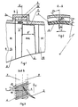
- FIG. 1 shows a portion of a casing 1 of a gas turbine axial flow compressor, and a rotor represented by one of a series of annular arrays of rotor blades 2 mounted on a rotor shaft (not shown) extending centrally through the casing.
- Annular arrays of stator blades 9 and 10 respectively, are secured to the casing upstream and downstream of the array of rotor blades 2.
- anti-stall tip treatment means are provided adjacent the blade tips.
- the treatment means in this example comprises an annular cavity 3 defined by a protruding U-shaped cross-section member 3a of the casing and an annular grid 3b of spaced ribs 4 between the cavity 3 and the compressor flow path 6 through the arrays of blading.
- the ribs 4 define a series of slots 5 of width ⁇ st through which there is communication between the cavity 3 and the flow path.
- the slots 5 overlap the rotor blade tips and flow path immediately upstream of the rotor blades, and the axial extent L of the cavity 3 corresponds to that of the slots.
- the ribs 4 and slots 5 extend parallel to each other. They are inclined outwardly in the direction of rotation U of the rotor blades 2 at-an angle ⁇ r to the radial direction, as shown in Fig. 2.
- the angle ⁇ r is constant along the length of the tip treatment means in this example but it may vary.
- the axes of the ribs 4 and slots 5 are also inclined at an angle ⁇ a (Fig. 3) with respect to the direction of flow velocity V 1 upstream of the rotor blades 2, shown in Fig. 3 at an angle ⁇ to the axial direction X-X.
- the angle ⁇ a is shown constant along the length of the tip treatment means but like the angle ⁇ r it may vary.
- angles ⁇ r should lie in the range 30° to 50°.
- the pressure in the forward section of interblade channel 8 does not exceed the pressure in the region 7 of the rotor blade tips upstream of the rotor blade array, so that there is no flow of air through the cavity 3 from the region of the rotor blades.
- the pressure gradient may cause air to be drawn into the cavity 3 through the slots 5 to flow from there into the flow path 6 in the rotor blade region.
- a decrease in the air flow rate through the compressor and an increase in the pressure downstream thereof, or a local decrease in flow velocity in the rotor tip region upstream of the rotor blades 2 cause an increase in the blade angles of incidence.
- Such conditions lead to a tendency for the pressure in the forward section of the interblade channel 8 to increase and exceed the pressure in the rotor tip region of the flow path upstream of the rotor blades 2.
- the annular cavity 3 serves as a bypass passage through which a reverse flow of air is transported out of the rotor blade region when the pressure downstream thereof exceeds some maximum value. Under incipient tip stall conditions it can therefore prevent discharge of this flow directly out of the rotor blade region into the entry flow path thereof.
- the annular cavity 3 also serves to decrease any circumferential non-uniformity of pressure and reduce flow fluctuations caused by the rotating blades 2 passing the slots 5. It can also help to prevent the formation of discrete stall zones.
- the cavity height H is chosen in the range of 0.2 to 0.5 of the grid axial length L. A decrease of H below 0.2L can reduce the tip treatment efficiency while an increase of H above 0.5L does not improve the efficiency of the tip treatment means but increases its overall radial dimensions.
- the optimum value of the length L is dependent on geometric and aerodynamic parameters of the rotor. For example, for a stage having a moderate head coefficient and blade aspect ratio AR (rotor blade height rotor blade chord) between 1.5 and 2.5, optimum L is approximately equal to b', the blade axial tip chord projection. For a stage with a large head and low aspect ratio, AR ⁇ 1, optimum L is approximately 0.5 to 0.6b.
- All geometric parameters of the elements of the tip treatment means may be chosen to ensure maximum efficiency in near-stall and stall regimes and minimise any decrease of efficiency at optimal flow regimes.
- ⁇ r is below 30° losses due to the flow of air out of the rotor blade region into the annular cavity increase.
- ⁇ r exceeds the upper limit of 50° there is an increase of losses in the flow of air from the annular cavity into the flow path upstream of the rotor.
- the ratio of grating pitch t to slot width ⁇ st is chosen in the range of 1.5 to 2.0. Reducing this ratio below 1.5 makes it necessary either to decrease the rib thickness, which can give an unacceptable reduction of strength under periodic loading, or to increase excessively the radial length of the ribs and the entire tip treatment means.
- a ratio significantly above 2.0 causes an increase of losses at air flow discharge out of the rotor blade region into the annular cavity and consequently a decrease in efficiency of the tip treatment means.
- the ratio of the rib radial height h to slot width ⁇ st is in the range 1.1 to 1.8. Below the lower limit of this ratio there is a decrease in grid solidity and even.the lower limit is best used only in the lower part of the range of ⁇ r . Increase of the ratio beyond the indicated upper limit can cause an increase in friction losses in the air circulation.
- the grid axial length L may vary from 0.5 to 1.5 of the axial projection b of the rotor blade tip chord. Within this range, L may depend largely on the aerodynamic loading of a stage and the aspect ratio of its blades. Decrease of L below 0.5 has an adverse effect on the efficiency of the tip treatment means, and an increase above 1.5 is possible only by increasing the length of the treatment region extending over the flow path 6 upstream of the rotor blades, so is limited by the construction of the compressor elements upstream of the rotor blades, and does not result in an increase in tip treatment efficiency.
- the tip treatment of the invention is also applicable to the stator blades, but at their radially inner ends. However, it is rare for compressor flow stability to be compromised by stator tip stall and the effects of the tip treatment are significantly less on stator blading.
Landscapes
- Engineering & Computer Science (AREA)
- Mechanical Engineering (AREA)
- General Engineering & Computer Science (AREA)
- Structures Of Non-Positive Displacement Pumps (AREA)
Claims (6)
- Verdichter, umfassend ein Gehäuse (1), in dem sich ringförmige Anordnungen von Rotorschaufeln (2) und Statorschaufeln (9, 10) befinden, wobei das Gehäuse einen ringförmigen Hohlraum (3) aufweist, der sich über den Enden von zumindest einer Anordnung von Schaufeln (2) erstreckt, wobei der Hohlraum mit dem Strömungsweg durch den Verdichter hindurch sowohl stromaufwärts von als auch axial zusammenfallend mit der Schaufelanordnung über Schlitze (5) kommuniziert, die durch ein ringförmiges Gitter (3b) von Rippen (4) gebildet werden, die relativ zur Radialrichtung schräg geneigt sind, dadurch gekennzeichnet, daß die Rippen (4) in einem Winkel (ϕr) von 30-50° zur Radialrichtung geneigt sind, daß der Abstand (t) der Rippen zur Schlitzbreite (δs) zwischen Rippen am Umfang im Verhältnis von 1,5 bis 2,0 steht, daß die Radialprojektion (h) der Höhe der Rippen zur Schlitzbreite im Verhältnis von 1,1 bis 1,8 steht, daß die Axiallänge (L) des Rippengitters zur Axialprojektion (b') der Schaufelendenlänge der Anordnung von Schaufeln (2) im Verhältnis von 0,5 bis 1,5 steht und daß die Hohlraumhöhe (H) außerhalb der Rippen zur Axiallänge (L) des Gitters im Verhältnis von 0,2 bis 0,5 steht.
- Verdichter nach Anspruch 1, worin die Rippen (4) zur Strömungsrichtung (V) durch den Verdichter hindurch schräg geneigt sind.
- Verdichter nach Anspruch 2, worin der Rippenneigungswinkel entlang der Axiallänge des Gitters (3b) variiert.
- Verdichter nach Anspruch 1, worin der Neigungswinkel der Rippen (4) zur Radialrichtung entlang der Axiallänge des Gitters (3b) konstant ist.
- Verdichter nach Anspruch 1 in Form eines Axialstromverdichters.
- Verdichter nach Anspruch 1 in Form eines Mischstromverdichters.
Applications Claiming Priority (3)
| Application Number | Priority Date | Filing Date | Title |
|---|---|---|---|
| SU9312990 | 1993-03-11 | ||
| RU9393012990A RU2034175C1 (ru) | 1993-03-11 | 1993-03-11 | Турбокомпрессор |
| PCT/GB1994/000481 WO1994020759A1 (en) | 1993-03-11 | 1994-03-11 | Anti-stall tip treatment means |
Publications (2)
| Publication Number | Publication Date |
|---|---|
| EP0688400A1 EP0688400A1 (de) | 1995-12-27 |
| EP0688400B1 true EP0688400B1 (de) | 1997-04-23 |
Family
ID=20138489
Family Applications (1)
| Application Number | Title | Priority Date | Filing Date |
|---|---|---|---|
| EP94909187A Expired - Lifetime EP0688400B1 (de) | 1993-03-11 | 1994-03-11 | Schaufelspitzeneinrichtung zum schutz gegen strömungsablösung |
Country Status (6)
| Country | Link |
|---|---|
| US (1) | US5762470A (de) |
| EP (1) | EP0688400B1 (de) |
| AU (1) | AU6212094A (de) |
| DE (1) | DE69402843T2 (de) |
| RU (1) | RU2034175C1 (de) |
| WO (1) | WO1994020759A1 (de) |
Families Citing this family (93)
| Publication number | Priority date | Publication date | Assignee | Title |
|---|---|---|---|---|
| RU2148732C1 (ru) * | 1998-05-05 | 2000-05-10 | Открытое акционерное общество Самарский научно-технический комплекс им. Н.Д. Кузнецова | Ступень турбомашины |
| US6231301B1 (en) | 1998-12-10 | 2001-05-15 | United Technologies Corporation | Casing treatment for a fluid compressor |
| RU2143595C1 (ru) * | 1999-01-15 | 1999-12-27 | Иркутское высшее военное авиационное инженерное училище | Осевой компрессор |
| US6527509B2 (en) * | 1999-04-26 | 2003-03-04 | Hitachi, Ltd. | Turbo machines |
| DE19920524C2 (de) * | 1999-05-05 | 2001-12-06 | Daimler Chrysler Ag | Radialverdichter |
| US6220012B1 (en) * | 1999-05-10 | 2001-04-24 | General Electric Company | Booster recirculation passageway and methods for recirculating air |
| US6290458B1 (en) | 1999-09-20 | 2001-09-18 | Hitachi, Ltd. | Turbo machines |
| US6302640B1 (en) * | 1999-11-10 | 2001-10-16 | Alliedsignal Inc. | Axial fan skip-stall |
| US6234747B1 (en) * | 1999-11-15 | 2001-05-22 | General Electric Company | Rub resistant compressor stage |
| GB2356588B (en) * | 1999-11-25 | 2003-11-12 | Rolls Royce Plc | Processing tip treatment bars in a gas turbine engine |
| RU2162165C1 (ru) * | 1999-12-10 | 2001-01-20 | Центральный институт авиационного моторостроения им. П.И. Баранова | Турбокомпрессор |
| RU2162164C1 (ru) * | 1999-12-10 | 2001-01-20 | Центральный институт авиационного моторостроения им. П.И. Баранова | Турбокомпрессор |
| EP1134427B1 (de) * | 2000-03-17 | 2004-09-22 | Hitachi, Ltd. | Turbomaschinen |
| JP3494118B2 (ja) * | 2000-04-07 | 2004-02-03 | 石川島播磨重工業株式会社 | 遠心圧縮機の作動域拡大方法及び装置 |
| RU2175410C1 (ru) * | 2000-04-18 | 2001-10-27 | Открытое акционерное общество "Авиадвигатель" | Компрессор газотурбинного двигателя |
| RU2172432C1 (ru) * | 2000-04-24 | 2001-08-20 | Азбель Александр Борисович | Турбокомпрессор, например, для наддува двигателя внутреннего сгорания |
| GB2362432B (en) * | 2000-05-19 | 2004-06-09 | Rolls Royce Plc | Tip treatment bars in a gas turbine engine |
| GB2363167B (en) * | 2000-06-06 | 2004-06-09 | Rolls Royce Plc | Tip treatment bars in a gas turbine engine |
| JP3862137B2 (ja) * | 2000-09-20 | 2006-12-27 | 淳一 黒川 | ターボ形水力機械 |
| GB2373023B (en) | 2001-03-05 | 2004-12-22 | Rolls Royce Plc | Tip treatment bar components |
| GB2373022B (en) | 2001-03-05 | 2005-06-22 | Rolls Royce Plc | Tip treatment assembly for a gas turbine engine |
| GB2373024B (en) | 2001-03-05 | 2005-06-22 | Rolls Royce Plc | Tip treatment bars for gas turbine engines |
| GB2373021B (en) | 2001-03-05 | 2005-01-12 | Rolls Royce Plc | A tip treatment bar with a damping material |
| FR2823532B1 (fr) * | 2001-04-12 | 2003-07-18 | Snecma Moteurs | Systeme de decharge pour turboreacteur ou turbopropulseur a commande simplifiee |
| RU2214535C2 (ru) * | 2001-07-05 | 2003-10-20 | Открытое акционерное общество "Авиадвигатель" | Способ управления перепуском воздуха в компрессоре двухвального двухконтурного газотурбинного двигателя |
| DE10135003C1 (de) | 2001-07-18 | 2002-10-02 | Mtu Aero Engines Gmbh | Verdichtergehäusestruktur |
| RU2206796C2 (ru) * | 2001-10-31 | 2003-06-20 | ООО "Самаратрансгаз" | Осевой многоступенчатый компрессор газотурбинного двигателя |
| DE10205363A1 (de) * | 2002-02-08 | 2003-08-21 | Rolls Royce Deutschland | Gasturbine |
| DE60320537T2 (de) * | 2002-02-28 | 2008-07-31 | Mtu Aero Engines Gmbh | Kompressor mit schaufelspitzeneinrichtung |
| CA2495186C (en) * | 2002-02-28 | 2010-04-27 | Mtu Aero Engines Gmbh | Recirculation structure for turbocompressors |
| RU2208177C1 (ru) * | 2002-07-15 | 2003-07-10 | Открытое акционерное общество Авиамоторный научно-технический комплекс "Союз" | Двухконтурный турбореактивный двигатель |
| GB0216952D0 (en) * | 2002-07-20 | 2002-08-28 | Rolls Royce Plc | Gas turbine engine casing and rotor blade arrangement |
| DE10330084B4 (de) * | 2002-08-23 | 2010-06-10 | Mtu Aero Engines Gmbh | Rezirkulationsstruktur für Turboverdichter |
| CA2496543C (en) * | 2002-08-23 | 2010-08-10 | Mtu Aero Engines Gmbh | Recirculation structure for a turbocompressor |
| RU2246640C1 (ru) * | 2003-07-22 | 2005-02-20 | Федеральное государственное унитарное предприятие "Центральный институт авиационного моторостроения им. П.И. Баранова" | Способ контроля режимов работы компрессорной системы и устройство для его реализации |
| GB2418956B (en) * | 2003-11-25 | 2006-07-05 | Rolls Royce Plc | A compressor having casing treatment slots |
| DE10355240A1 (de) | 2003-11-26 | 2005-07-07 | Rolls-Royce Deutschland Ltd & Co Kg | Strömungsarbeitsmaschine mit Fluidentnahme |
| RU2290542C2 (ru) * | 2003-11-27 | 2006-12-27 | Открытое акционерное общество "Специальное конструкторское бюро турбонагнетателей" (ОАО "СКБТ") | Консольный турбокомпрессор |
| RU2290543C2 (ru) * | 2003-11-27 | 2006-12-27 | Открытое акционерное общество "Специальное конструкторское бюро турбонагнетателей" (ОАО "СКБТ") | Турбокомпрессор |
| RU2253758C1 (ru) * | 2004-01-16 | 2005-06-10 | Федеральное государственное унитарное предприятие "Центральный институт авиационного моторостроения им. П.И. Баранова" | Компрессор |
| DE102004055439A1 (de) * | 2004-11-17 | 2006-05-24 | Rolls-Royce Deutschland Ltd & Co Kg | Strömungsarbeitsmaschine mit dynamischer Strömungsbeeinflussung |
| RU2282754C1 (ru) * | 2005-01-24 | 2006-08-27 | Федеральное государственное унитарное предприятие "Центральный институт авиационного моторостроения им. П.И. Баранова" | Надроторное устройство компрессора и осевой компрессор |
| FR2882112B1 (fr) * | 2005-02-16 | 2007-05-11 | Snecma Moteurs Sa | Prelevement en tete des roues mobiles de compresseur haute pression de turboreacteur |
| US7861823B2 (en) * | 2005-11-04 | 2011-01-04 | United Technologies Corporation | Duct for reducing shock related noise |
| EP1862641A1 (de) * | 2006-06-02 | 2007-12-05 | Siemens Aktiengesellschaft | Ringförmiger Strömungskanal für eine in Axialrichtung von einem Hauptstrom durchströmbare Strömungsmaschine |
| WO2008143603A1 (en) * | 2006-12-28 | 2008-11-27 | Carrier Corporation | Axial fan casing design with circumferentially spaced wedges |
| FR2912789B1 (fr) * | 2007-02-21 | 2009-10-02 | Snecma Sa | Carter avec traitement de carter, compresseur et turbomachine comportant un tel carter. |
| US7942625B2 (en) * | 2007-04-04 | 2011-05-17 | Honeywell International, Inc. | Compressor and compressor housing |
| DE102007037924A1 (de) * | 2007-08-10 | 2009-02-12 | Rolls-Royce Deutschland Ltd & Co Kg | Strömungsarbeitsmaschine mit Ringkanalwandausnehmung |
| US7988410B1 (en) | 2007-11-19 | 2011-08-02 | Florida Turbine Technologies, Inc. | Blade tip shroud with circular grooves |
| DE102008011644A1 (de) * | 2008-02-28 | 2009-09-03 | Rolls-Royce Deutschland Ltd & Co Kg | Gehäusestrukturierung für Axialverdichter im Nabenbereich |
| DE102008031982A1 (de) * | 2008-07-07 | 2010-01-14 | Rolls-Royce Deutschland Ltd & Co Kg | Strömungsarbeitsmaschine mit Nut an einem Laufspalt eines Schaufelendes |
| DE102008037154A1 (de) | 2008-08-08 | 2010-02-11 | Rolls-Royce Deutschland Ltd & Co Kg | Strömungsarbeitsmaschine |
| FR2940374B1 (fr) | 2008-12-23 | 2015-02-20 | Snecma | Carter de compresseur a cavites optimisees. |
| US8602720B2 (en) * | 2010-06-22 | 2013-12-10 | Honeywell International Inc. | Compressors with casing treatments in gas turbine engines |
| GB2483060B (en) * | 2010-08-23 | 2013-05-15 | Rolls Royce Plc | A turbomachine casing assembly |
| GB2487900B (en) * | 2011-02-03 | 2013-02-06 | Rolls Royce Plc | A turbomachine comprising an annular casing and a bladed rotor |
| EP2532898A1 (de) * | 2011-06-08 | 2012-12-12 | Siemens Aktiengesellschaft | Axialturboverdichter |
| DE102011107523B4 (de) * | 2011-07-15 | 2016-08-11 | MTU Aero Engines AG | System zum Einblasen eines Fluids, Verdichter sowie Turbomaschine |
| FR2988146B1 (fr) * | 2012-03-15 | 2014-04-11 | Snecma | Carter pour roue a aubes de turbomachine ameliore et turbomachine equipee dudit carter |
| FR2989742B1 (fr) * | 2012-04-19 | 2014-05-09 | Snecma | Carter de compresseur a cavites a forme amont optimisee |
| CN102817873B (zh) * | 2012-08-10 | 2015-07-15 | 势加透博(北京)科技有限公司 | 航空发动机压气机的梯状间隙结构 |
| RU2623323C2 (ru) * | 2012-09-06 | 2017-06-23 | Сименс Акциенгезелльшафт | Турбомашина и способ ее работы |
| GB201318036D0 (en) * | 2013-10-11 | 2013-11-27 | Rolls Royce Plc | Tip treatment bars in a turbine engine |
| US10378554B2 (en) | 2014-09-23 | 2019-08-13 | Pratt & Whitney Canada Corp. | Gas turbine engine with partial inlet vane |
| US10145301B2 (en) | 2014-09-23 | 2018-12-04 | Pratt & Whitney Canada Corp. | Gas turbine engine inlet |
| US10539154B2 (en) * | 2014-12-10 | 2020-01-21 | General Electric Company | Compressor end-wall treatment having a bent profile |
| US9938848B2 (en) | 2015-04-23 | 2018-04-10 | Pratt & Whitney Canada Corp. | Rotor assembly with wear member |
| US9957807B2 (en) * | 2015-04-23 | 2018-05-01 | Pratt & Whitney Canada Corp. | Rotor assembly with scoop |
| CN105317472B (zh) * | 2015-12-01 | 2016-11-30 | 秦皇岛鱼麟电力设备有限公司 | 一种涡轮机随动悬浮式汽封带用弹性片及其汽封结构 |
| RU2645100C1 (ru) * | 2016-09-28 | 2018-02-15 | ФЕДЕРАЛЬНОЕ ГОСУДАРСТВЕННОЕ БЮДЖЕТНОЕ ОБРАЗОВАТЕЛЬНОЕ УЧРЕЖДЕНИЕ ВЫСШЕГО ОБРАЗОВАНИЯ "Брянский государственный технический университет" | Периферийное устройство для снижения утечек теплоносителя |
| US10724540B2 (en) | 2016-12-06 | 2020-07-28 | Pratt & Whitney Canada Corp. | Stator for a gas turbine engine fan |
| US10690146B2 (en) | 2017-01-05 | 2020-06-23 | Pratt & Whitney Canada Corp. | Turbofan nacelle assembly with flow disruptor |
| US10465539B2 (en) * | 2017-08-04 | 2019-11-05 | Pratt & Whitney Canada Corp. | Rotor casing |
| RU2705502C1 (ru) * | 2018-11-02 | 2019-11-07 | Публичное акционерное общество "ОДК - Уфимское моторостроительное производственное объединение" (ПАО "ОДК-УМПО") | Турбокомпрессор |
| US11473438B2 (en) * | 2019-06-04 | 2022-10-18 | Honeywell International Inc. | Grooved rotor casing system using additive manufacturing method |
| CN112832878B (zh) * | 2020-12-31 | 2022-10-25 | 南昌航空大学 | 一种涡轮泄漏流控制的非定常机匣处理结构 |
| US11480063B1 (en) * | 2021-09-27 | 2022-10-25 | General Electric Company | Gas turbine engine with inlet pre-swirl features |
| FR3145195A1 (fr) | 2023-01-19 | 2024-07-26 | Safran | Traitement de carter non axisymétrique avec plenum à ouverture pilotée |
| FR3149650B1 (fr) | 2023-06-12 | 2025-06-13 | Safran | Traitement de carter non axisymétrique avec plenum ondulé |
| US11970985B1 (en) | 2023-08-16 | 2024-04-30 | Rolls-Royce North American Technologies Inc. | Adjustable air flow plenum with pivoting vanes for a fan of a gas turbine engine |
| US12018621B1 (en) | 2023-08-16 | 2024-06-25 | Rolls-Royce North American Technologies Inc. | Adjustable depth tip treatment with rotatable ring with pockets for a fan of a gas turbine engine |
| US12085021B1 (en) | 2023-08-16 | 2024-09-10 | Rolls-Royce North American Technologies Inc. | Adjustable air flow plenum with movable closure for a fan of a gas turbine engine |
| US12066035B1 (en) | 2023-08-16 | 2024-08-20 | Rolls-Royce North American Technologies Inc. | Adjustable depth tip treatment with axial member with pockets for a fan of a gas turbine engine |
| US12078070B1 (en) | 2023-08-16 | 2024-09-03 | Rolls-Royce North American Technologies Inc. | Adjustable air flow plenum with sliding doors for a fan of a gas turbine engine |
| US11965528B1 (en) | 2023-08-16 | 2024-04-23 | Rolls-Royce North American Technologies Inc. | Adjustable air flow plenum with circumferential movable closure for a fan of a gas turbine engine |
| FR3156861A1 (fr) | 2023-12-13 | 2025-06-20 | Safran | Traitement de carter non axisymétrique à ouverture piloté avec plenum |
| US12258870B1 (en) | 2024-03-08 | 2025-03-25 | Rolls-Royce North American Technologies Inc. | Adjustable fan track liner with slotted array active fan tip treatment for distortion tolerance |
| US12286936B1 (en) | 2024-05-09 | 2025-04-29 | Rolls-Royce North American Technologies Inc. | Adjustable fan track liner with groove array active fan tip treatment for distortion tolerance |
| US12215712B1 (en) | 2024-05-09 | 2025-02-04 | Rolls-Royce North American Technologies Inc. | Adjustable fan track liner with dual grooved array active fan tip treatment for distortion tolerance |
| US12209541B1 (en) | 2024-05-09 | 2025-01-28 | Rolls-Royce North American Technologies Inc. | Adjustable fan track liner with dual slotted array active fan tip treatment for distortion tolerance |
| US12209502B1 (en) | 2024-06-28 | 2025-01-28 | Rolls-Royce North American Technologies Inc. | Active fan tip treatment using rotating drum array with axial channels in fan track liner for distortion tolerance |
| US12168983B1 (en) | 2024-06-28 | 2024-12-17 | Rolls-Royce North American Technologies Inc. | Active fan tip treatment using rotating drum array in fan track liner with axial and circumferential channels for distortion tolerance |
Family Cites Families (9)
| Publication number | Priority date | Publication date | Assignee | Title |
|---|---|---|---|---|
| GB479427A (en) * | 1935-05-31 | 1938-01-31 | Gyoergy Jendrassik | Improvements in rotary compressors |
| DE722424C (de) * | 1940-04-16 | 1942-07-09 | Friedrich Schicht | Gleichdruck-Geblaese oder Gleichdruck-Pumpe |
| GB1454630A (en) * | 1973-12-11 | 1976-11-03 | Electricite De France | Axial-flow fan |
| GB2017228B (en) * | 1977-07-14 | 1982-05-06 | Pratt & Witney Aircraft Of Can | Shroud for a turbine rotor |
| US4212585A (en) * | 1978-01-20 | 1980-07-15 | Northern Research And Engineering Corporation | Centrifugal compressor |
| SU757774A1 (ru) * | 1978-05-04 | 1980-08-23 | Vladimir V Semov | · противопомг.ажное устройство осевого компрессора |
| JPS6318799Y2 (de) * | 1980-12-02 | 1988-05-26 | ||
| US4479755A (en) * | 1982-04-22 | 1984-10-30 | A/S Kongsberg Vapenfabrikk | Compressor boundary layer bleeding system |
| CH675279A5 (de) * | 1988-06-29 | 1990-09-14 | Asea Brown Boveri |
-
1993
- 1993-03-11 RU RU9393012990A patent/RU2034175C1/ru not_active IP Right Cessation
-
1994
- 1994-03-11 US US08/513,903 patent/US5762470A/en not_active Expired - Lifetime
- 1994-03-11 DE DE69402843T patent/DE69402843T2/de not_active Expired - Lifetime
- 1994-03-11 EP EP94909187A patent/EP0688400B1/de not_active Expired - Lifetime
- 1994-03-11 WO PCT/GB1994/000481 patent/WO1994020759A1/en not_active Ceased
- 1994-03-11 AU AU62120/94A patent/AU6212094A/en not_active Abandoned
Also Published As
| Publication number | Publication date |
|---|---|
| DE69402843T2 (de) | 1997-09-04 |
| DE69402843D1 (de) | 1997-05-28 |
| EP0688400A1 (de) | 1995-12-27 |
| US5762470A (en) | 1998-06-09 |
| RU2034175C1 (ru) | 1995-04-30 |
| AU6212094A (en) | 1994-09-26 |
| WO1994020759A1 (en) | 1994-09-15 |
Similar Documents
| Publication | Publication Date | Title |
|---|---|---|
| EP0688400B1 (de) | Schaufelspitzeneinrichtung zum schutz gegen strömungsablösung | |
| US5529457A (en) | Centrifugal compressor | |
| US5228832A (en) | Mixed flow compressor | |
| EP0622549B1 (de) | Kreiselverdichter und Diffusor mit Schaufeln | |
| EP0526387B1 (de) | Kreiselverdichter | |
| US8308420B2 (en) | Centrifugal compressor, impeller and operating method of the same | |
| EP0610051B1 (de) | Diffusor mit Rippen | |
| US6203275B1 (en) | Centrifugal compressor and diffuser for centrifugal compressor | |
| US6722847B2 (en) | Fan for a turbofan gas turbine engine | |
| RU2228461C2 (ru) | Профилированная лопатка компрессора, имеющая двойной изгиб | |
| US4093401A (en) | Compressor impeller and method of manufacture | |
| US4349314A (en) | Compressor diffuser and method | |
| EP1826361B1 (de) | Gasturbinenschaufel | |
| US7004722B2 (en) | Axial flow compressor | |
| EP0425651A4 (en) | Compressor shroud air bleed passages | |
| EP0083199A2 (de) | Steuern des Pumpens eines Flüssigkeitsverdichters | |
| EP2221487B1 (de) | Zentrifugalverdichter | |
| US4902200A (en) | Variable diffuser wall with ribbed vanes | |
| CA1314486C (en) | Axial flow compressor surge margin improvement | |
| EP0446900B1 (de) | Diagonal-Verdichter | |
| US7789631B2 (en) | Compressor of a gas turbine and gas turbine | |
| US20080025840A1 (en) | Turbomachine with rotors of high specific energy transfer | |
| RU2162164C1 (ru) | Турбокомпрессор | |
| JP2001248597A (ja) | ターボ圧縮機及びターボ送風機 | |
| JP5232721B2 (ja) | 遠心圧縮機 |
Legal Events
| Date | Code | Title | Description |
|---|---|---|---|
| PUAI | Public reference made under article 153(3) epc to a published international application that has entered the european phase |
Free format text: ORIGINAL CODE: 0009012 |
|
| 17P | Request for examination filed |
Effective date: 19951002 |
|
| AK | Designated contracting states |
Kind code of ref document: A1 Designated state(s): DE FR GB |
|
| GRAG | Despatch of communication of intention to grant |
Free format text: ORIGINAL CODE: EPIDOS AGRA |
|
| 17Q | First examination report despatched |
Effective date: 19960703 |
|
| GRAH | Despatch of communication of intention to grant a patent |
Free format text: ORIGINAL CODE: EPIDOS IGRA |
|
| GRAH | Despatch of communication of intention to grant a patent |
Free format text: ORIGINAL CODE: EPIDOS IGRA |
|
| GRAA | (expected) grant |
Free format text: ORIGINAL CODE: 0009210 |
|
| AK | Designated contracting states |
Kind code of ref document: B1 Designated state(s): DE FR GB |
|
| REF | Corresponds to: |
Ref document number: 69402843 Country of ref document: DE Date of ref document: 19970528 |
|
| ET | Fr: translation filed | ||
| PLBE | No opposition filed within time limit |
Free format text: ORIGINAL CODE: 0009261 |
|
| STAA | Information on the status of an ep patent application or granted ep patent |
Free format text: STATUS: NO OPPOSITION FILED WITHIN TIME LIMIT |
|
| 26N | No opposition filed | ||
| REG | Reference to a national code |
Ref country code: GB Ref legal event code: IF02 |
|
| PGFP | Annual fee paid to national office [announced via postgrant information from national office to epo] |
Ref country code: FR Payment date: 20130405 Year of fee payment: 20 Ref country code: DE Payment date: 20130327 Year of fee payment: 20 Ref country code: GB Payment date: 20130327 Year of fee payment: 20 |
|
| REG | Reference to a national code |
Ref country code: DE Ref legal event code: R071 Ref document number: 69402843 Country of ref document: DE |
|
| REG | Reference to a national code |
Ref country code: GB Ref legal event code: PE20 Expiry date: 20140310 |
|
| PG25 | Lapsed in a contracting state [announced via postgrant information from national office to epo] |
Ref country code: DE Free format text: LAPSE BECAUSE OF EXPIRATION OF PROTECTION Effective date: 20140312 Ref country code: GB Free format text: LAPSE BECAUSE OF EXPIRATION OF PROTECTION Effective date: 20140310 |