EP0688467B1 - Lame de disjoncteur, pour courants eleves - Google Patents
Lame de disjoncteur, pour courants eleves Download PDFInfo
- Publication number
- EP0688467B1 EP0688467B1 EP95901977A EP95901977A EP0688467B1 EP 0688467 B1 EP0688467 B1 EP 0688467B1 EP 95901977 A EP95901977 A EP 95901977A EP 95901977 A EP95901977 A EP 95901977A EP 0688467 B1 EP0688467 B1 EP 0688467B1
- Authority
- EP
- European Patent Office
- Prior art keywords
- blade
- section
- circuit breaker
- legs
- broad
- Prior art date
- Legal status (The legal status is an assumption and is not a legal conclusion. Google has not performed a legal analysis and makes no representation as to the accuracy of the status listed.)
- Expired - Lifetime
Links
- 210000002414 leg Anatomy 0.000 description 12
- 230000004044 response Effects 0.000 description 7
- 230000007246 mechanism Effects 0.000 description 5
- 239000002184 metal Substances 0.000 description 5
- 230000004048 modification Effects 0.000 description 3
- 238000012986 modification Methods 0.000 description 3
- 230000013011 mating Effects 0.000 description 2
- 230000009471 action Effects 0.000 description 1
- 238000005452 bending Methods 0.000 description 1
- 238000002788 crimping Methods 0.000 description 1
- 238000010891 electric arc Methods 0.000 description 1
- 239000000835 fiber Substances 0.000 description 1
- 238000010438 heat treatment Methods 0.000 description 1
- 238000000926 separation method Methods 0.000 description 1
- 210000000689 upper leg Anatomy 0.000 description 1
Images


Classifications
-
- H—ELECTRICITY
- H01—ELECTRIC ELEMENTS
- H01H—ELECTRIC SWITCHES; RELAYS; SELECTORS; EMERGENCY PROTECTIVE DEVICES
- H01H73/00—Protective overload circuit-breaking switches in which excess current opens the contacts by automatic release of mechanical energy stored by previous operation of a hand reset mechanism
- H01H73/02—Details
- H01H73/04—Contacts
Definitions
- the present invention relates generally to circuit breakers and, more particularly, to a high current capacity blade for a circuit breaker.
- circuit breakers Use of circuit breakers is widespread in modern-day residential, commercial and industrial electric systems, and they constitute an indispensable component of such systems toward providing protection against over-current conditions.
- Various circuit breaker mechanisms have evolved and have been perfected over time on the basis of application-specific factors such as current capacity, response time, and the type of reset (manual or remote) function desired of the breaker.
- thermo-magnetic tripping device to "trip" a latch in response to a specific range of over-current conditions.
- the tripping action is caused by a significant deflection in a bi-metal or thermostat-metal element which responds to changes in temperature due to resistance heating caused by flow of the circuit's electric current through the element.
- the thermostat metal element is typically in the form of a flat metal member and operates in conjunction with a latch so that metal member deflection releases the latch after a time delay corresponding to a predetermined over-current threshold in order to "break" the current circuit associated therewith.
- Circuit breaker mechanisms of this type often include an electro-magnet operating upon a lever to release the breaker latch in the presence of a short circuit or very high current condition.
- a handle or push button mechanism is also provided for opening up the electric contacts to the requisite separation width and sufficiently fast to realize adequate current interruption.
- Double-break circuit breaker includes two sets of current-breaking contacts to accommodate a higher level of over-current conditions than is accommodated by the one discussed above.
- One such double-break circuit breaker implements its two sets of contacts using the respective ends of an elongated rotatable blade as movable contacts which meet non-movable contacts disposed adjacent the non-movable contacts.
- the non-movable contacts are located on the ends of respective U-shaped stationary terminals, so that an electro-magnetic blow-off force ensues when the current, exceeding the threshold level, passes through the U-shaped terminals.
- the blow-off force causes the elongated rotatable blade to rotate and the two sets of contacts to separate simultaneously.
- Another type of double-break circuit breaker implements its two sets of contacts using separate and independent structures.
- one set of contacts may be implemented using the previously-discussed thremo-magnetic tripping device to trip the current path at low-level current conditions, and the other set of contacts using an intricate and current-sensitive arrangement which separates its contacts in response to high-level blow-off current conditions. See, for example, U.S. Patent Nos. 3,944,953, 3,943,316 and 3,943,472, each of which is assigned to the instant assignee.
- WO-A-93/22784 discloses a circuit breaker blade according to the preamble of claim 1 having a blade body carrying a moveable contact at its front section and having a pair of parallel L-shaped blade legs located at its rear section.
- An object of the present invention is to provide a circuit breaker blade having a high current capacity.
- a related object is to provide a circuit breaker blade capable of handling the high contact force required for the high current capacity.
- Another object of the present invention is to provide a circuit breaker blade having a high interruption capacity and, therefore, a high operational performance.
- a high current capacity blade for a circuit breaker comprising: a conductive blade body having front and rear sections connected to one another, said rear section including a surface attachment area for fastening a flexible connector of the circuit of the circuit breaker thereto; a strain relief tang extending from said rear section of said blade body for engaging the flexible connector to stabilise the fastening of the flexible connector to the surface attachment area; a pair of substantially parallel L-shaped blade legs spaced from one another to permit a toggle spring to pass therebetween, each of said blade legs having first and second ends, said first ends of said blades being connected to said rear portion of said blade body and said second ends including respective blade pivots for engaging notches in a handle of the circuit breaker, characterised by a broad conductive lateral section connected to and extending laterally from said front section, said broad lateral section including a blade tab for engaging the toggle spring of the circuit breaker; and a broad moveable contact mounted on said broad lateral section and adapted to interface with a stationary contact of the circuit
- FIG. 1 illustrates the basic configuration of a primary blade 32 embodying the present invention in the context of a double-break circuit breaker.
- the present invention is discussed in the context of such an exemplary double-break circuit breaker for illustrative purposes only, and the particular circuit breaker illustrated and described should not be construed to limit the possible applications for the present invention, as these applications encompass a wide variety of circuit breaker types.
- the double-break circuit breaker of FIG. 1 will first be described, followed by a detailed description of the primary blade 32, which embodies the principles of the present invention.
- the circuit breaker of FIG. 1 includes a circuit breaker base 14 which carries all of the internal components of the circuit breaker.
- the current path through the circuit breaker begins at a line terminal 16, and from the line terminal 16 the current path goes through a flexible pigtail 18.
- the flexible pigtail 18 is attached to a secondary blade 20 with a moveable contact 22 mating with a stationary contact 24.
- Current flows through the moveable and stationary contacts 22, 24 to the mid terminal 26, which is configured in an S form.
- the other side of the mid terminal 26 includes another stationary contact 28 connected thereto.
- a mating moveable contact 30 attached to the primary blade 32. Current flows through the stationary and moveable contacts 28, 30, through the primary blade 32, and into one end of a primary flexible connector or pigtail 34.
- the other end of the primary flexible connector 34 is attached to a bimetal 36, which provides the thermal tripping characteristics for the circuit breaker. Finally, the current flows from the bimetal 36 through a load terminal 38 and out of the load end of the circuit breaker via a lug 40.
- the primary section of the circuit breaker includes the primary blade 32, a trip lever 42, a handle 44, a magnetic armature 46, a pigtail 34, and a primary arc stack 13.
- the secondary section includes the secondary blade 20, the pigtail 18, an extension spring 48, and a secondary arc stack 10.
- the primary section provides the breaking capacity for all levels of current from one ampere to approximately 3000 amperes without operational assistance from the secondary section.
- the magnetic armature 46 is drawn to a yoke 50 during high current flow. This allows the trip lever 42 to disengage from the magnetic armature 46 and rotate to the trip position, which, in turn, allows the primary blade contact 30 to separate from the stationary contact 28 to break the current flow. As the contacts 28, 30 are separated, an arc voltage is generated in the primary arc stack 13.
- a thermal trip via the bimetal 36 results in the same sequence of events and, additionally, results in the trip lever 42 disengaging from the magnetic armature 46.
- the normal ON and OFF operation of the primary blade 32 occurs in response to rotation of the handle 44 in a clockwise or counterclockwise motion.
- the primary blade 32 In response to rotation of the handle 44 in either direction, the primary blade 32 either opens or closes the circuit via the primary moveable contact 30 and the primary stationary contact 28.
- Rotation of the primary blade 32 is tied directly to the handle 44 for the normal ON and OFF operation of the primary blade 32.
- the secondary section is not affected by the normal ON and OFF operation of the primary blade 32.
- the secondary blade contact 22 and the secondary stationary contact 24 remain closed.
- the secondary section of the circuit breaker has limited operation below 3000 amperes of fault current. However, at current levels above 3000 amperes, the secondary section begins to contribute to interruption performance.
- the secondary blade 20 derives contact force from the extension spring 48.
- the secondary blade 20 pivots about the blade pivot 52 with the extension spring 48 extended as the secondary blade 20 opens up in response to a current fault above 3000 amperes. There is no linkage of the secondary blade 20 to the primary blade 32, but rather the operation of the secondary and primary blades 20, 32 is totally separate and independent.
- the constriction resistance of the secondary blade contact 22 and the secondary stationary contact 24 provides a magnetic force that tries to separate the contacts.
- the current path configuration of the mid terminal 26 and the secondary blade 20 forms a magnetic blowoff loop which also tries to separate the contacts 22, 24.
- the addition of both of these opening forces to the secondary blade 20 causes the secondary blade 20 to separate at the contacts 22, 24.
- the extension spring 48 begins to stretch.
- the extension spring 48 permits the secondary blade 20 to continue to open as long as the force to open the blade is greater than the extension force of the spring 48.
- an arc voltage is generated in the secondary arc stack 10.
- the combination of the arc voltage generated by the secondary arc stack 10 and the arc voltage generated by the primary arc stack 13 make these voltages add together. This allows a very fast rise of arc voltage and also allows high levels of arc voltage consistent with double break circuit breakers.
- the secondary blade 20 As the current fault level rises higher and higher above 3000 amperes, the faster and higher the secondary blade 20 will be moved. As the interruption takes place and the electric arc is extinguished in the primary and secondary sections, the secondary blade 20 is biased to return to the closed position because of the spring bias from the extension spring 48. The primary blade 32 remains in the open or tripped position. At this point, the interruption of the current fault is complete With no opportunity to re-establish itself.
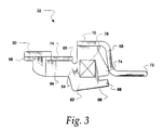
- FIGS. 2 and 3 illustrate the high current capacity primary blade 32 embodying the present invention and related to the blade shown in FIG. 12 of U.S. Patent Application Serial No. 07/878648 (issuing as Patent No. 5,245,302 on September 14, 1993), incorporated herein by reference.
- the primary blade 32 includes an integral blade body 54 bridging an integral lateral section 56 and a pair of blade legs 58.
- the lateral section 56 includes the moveable contact 30 connected thereto and interfacing with the stationary contact 28 (see FIG. 1).
- the lateral section 56 includes a blade tab 60 for engaging one end of a toggle spring (not shown).
- the primary blade 32 is z-axis assembled into the base 14 of the circuit breaker in such a way as to attach the blade tab 60 to a triplever hook via the toggle spring. Also, the blade legs 58 are engaged with respective notches in the circuit breaker handle 44.
- the primary blade 32 is situated in the base 14 with the blade body 54 positioned substantially parallel to the inner surface of base 14 and the lateral section 56 extending upwardly in a direction away from the inner surface of the base 14.
- the blade body 54 is integrally connected to the lateral section 56 and is positioned substantially orthogonal to the lateral section 56.
- the blade body 54 includes a rear portion 62 and a front portion 64 adjacent the lateral section 56.
- the rear and front portions 62, 64 are configured in the manner illustrated in FIG. 2.
- the rear portion 62 is wider than the front portion 64, and the front portion is connected to the approximate middle of the rear portion 62.
- the flexible connector 34 (see FIG. 1) is fastened to the surface attachment area 76 of the rear portion 62. This attachment is stabilized using a strain relief tang 66 connected to the rear portion 62 and extending laterally from the rear portion 62 in a direction opposite the lateral section 56.
- the flexible connector 34 is inserted into the region labelled 68 and crimped therein by the strain relief tang 66.
- the strain relief tang 66 is rotatably bent toward the rear portion 62 so that the flexible connector 34 is "sandwiched" between the strain relief tang 66 and the rear portion 62.
- the design of the strain relief tang 66 permits the strain relief tang 66 to secure a large flexible connector or multiple flexible connectors in the region 68.
- the pair of blade legs 58 are integrally connected to the rear portion 62 of the blade body 54 via a lateral waist section 70 extending in the same direction as the lateral section 56.
- the blade legs 58 are formed substantially parallel to one another and are spaced from one another to permit the toggle spring to pass therebetween.
- the blade legs 58 are formed with respective right-angled bends as shown in FIG. 2 and terminate in blade pivots 72.
- the blade pivots 72 are biased to sit in notches in the circuit breaker handle 44 shown in FIG. 1 because of the force applied by the toggle spring in connecting the blade tab 60 to the triplever hook adjacent the handle 44.
- the contact force required for the blade 32 is relatively high (28 to 30 ounces). This contact force is generated from a relatively strong force applied by the toggle spring, and the blade 32 includes several features designed to withstand this relatively strong force.
- the blade pivots 72 are rounded, i.e., have rolled radii. The rolled radii facilitate pivoting of the pivots 72 within the notches of the circuit breaker handle 44.
- the upper "thigh" portion of one of the blade legs 58 abuts against the rear edge 74 of the blade body 54. The purpose of having the blade leg 58 touch the blade body 54 is to provide additional support to the blade body 54.
- the blade body 54 Since the toggle spring applies a relatively strong force to the blade body 54 which is partially directed toward the blade legs 58, the blade body 54 exerts a torque about the waist section 70. The abutment between the blade leg 58 and the blade body 54 prevents the waist section 70 from bending due to this torque.
- the blade tab 60 is provided with additional strength to withstand the relatively strong force generated by the toggle spring connected thereto. This additional strength stems from the integrity of the primary blade 32.
- the blade tab 60 is formed within the integral lateral section 56, and the lateral section 56 is integrally connected to the blade body 54.
- the primary blade 32 is designed to carry currents in excess of 100 amperes.
- current flows from the moveable contact 30, through the lateral section 56 and the blade body 54, and to the interface 76 with the flexible connector 34.
- the moveable contact 30 is designed larger in size than the moveable contacts of existing blades.
- the large lateral section 56 supporting the moveable contact 30 not only increases the current capacity of the blade 32, but also increases the interruption capacity of the blade 32.
- the current capacity of the blade 32 is increased due to the relatively long current path between the lateral section 56 and the flexible connector attachment region 76, as well as the relatively large thickness of the blade body 54.
- a slide fiber 32 (FIG. 1) is hooked into the region 74 of the blade 32 and is used to provide the gas pressure to push the arc into the arc stack 13.
Landscapes
- Breakers (AREA)
- Coupling Device And Connection With Printed Circuit (AREA)
Claims (8)
- Une lame (32) de disjoncteur pour courants élevés, comprenant :un corps de lame conducteur (54) ayant des parties avant (64) et arrière (62) connectées l'une à l'autre, ladite partie arrière (62) présentant une région de fixation en surface (76) pour y fixer un cordon de raccordement souple du disjoncteur ;une queue de soulagement de traction (66) s'étendant à partir de ladite partie arrière (62) dudit corps de lame (54), prévue pour engager avec elle le cordon de raccordement souple afin de stabiliser la fixation de celui-ci sur la région de fixation en surface (76) ;une paire de jambes de lame (58) en forme de L sensiblement parallèles, écartées l'une de l'autre pour permettre à un ressort de basculement de passer entre elles, chacune desdites jambes de lame (58) ayant des première et seconde extrémités, lesdites premières extrémités desdites lames étant connectées à ladite partie arrière (62) dudit corps de lame, et lesdites secondes extrémités comprenant des pivots de lame respectifs (72) destinés à s'engager dans des encoches d'une manette (44) du disjoncteur, caractérisée par :une large partie latérale conductrice (56) connectée à ladite partie avant (64) et s'étendant latéralement à partir de celle-ci, ladite large partie latérale (56) comprenant une patte de lame (60) pour accrocher le ressort de basculement du disjoncteur; etun large contact mobile (30) monté sur ladite large partie latérale (56), et adapté pour coopérer avec un contact fixe du disjoncteur.
- Une lame selon la revendication 1, caractérisée en ce que lesdits pivots de lame (72) sont arrondis pour faciliter leur pivotement dans les encoches de la manette (44) du disjoncteur.
- Une lame selon la revendication 1 ou 2, caractérisée en ce que ladite queue de soulagement de traction (66) s'étend latéralement à partir de ladite partie arrière (62) dans une direction sensiblement à l'opposé de ladite large partie latérale conductrice (56).
- Une lame selon l'une quelconque des revendications précédentes, caractérisée en ce que l'une desdites jambes de lame (58) vient en contact contre ladite partie arrière (62) pour apporter du soutien audit corps de lame (54).
- Une lame selon l'une quelconque des revendications précédentes, caractérisée en ce que ladite partie arrière (62) est plus large que ladite partie avant (64), et ladite partie avant (64) est connectée centralement à ladite partie arrière (62).
- Une lame selon l'une quelconque des revendications précédentes, caractérisée en ce qu'elle comprend en outre une partie centrale (70) s'étendant latéralement à partir de ladite partie arrière (62) sensiblement dans la même direction que ladite partie latérale (56), ladite partie centrale (70) réunissant ladite partie arrière (62) et ladite paire de jambes de lame (58).
- Une lame selon l'une quelconque des revendications précédentes, caractérisée en ce que ladite partie latérale (56) est formée en une seule pièce avec elle, et dans laquelle ladite partie latérale (56) est connectée de façon monolithique à ladite partie avant (64).
- Une lame selon l'une quelconque des revendications précédentes, caractérisée en ce que lesdites jambes de lame (58) sont sensiblement parallèles audit corps de lame (54).
Applications Claiming Priority (3)
| Application Number | Priority Date | Filing Date | Title |
|---|---|---|---|
| US08/180,690 US5373272A (en) | 1994-01-13 | 1994-01-13 | High current capacity blade for a circuit breaker |
| US180690 | 1994-01-13 | ||
| PCT/US1994/013693 WO1995019635A1 (fr) | 1994-01-13 | 1994-11-21 | Lame de disjoncteur, pour courants eleves |
Publications (2)
| Publication Number | Publication Date |
|---|---|
| EP0688467A1 EP0688467A1 (fr) | 1995-12-27 |
| EP0688467B1 true EP0688467B1 (fr) | 1998-09-02 |
Family
ID=22661385
Family Applications (1)
| Application Number | Title | Priority Date | Filing Date |
|---|---|---|---|
| EP95901977A Expired - Lifetime EP0688467B1 (fr) | 1994-01-13 | 1994-11-21 | Lame de disjoncteur, pour courants eleves |
Country Status (6)
| Country | Link |
|---|---|
| US (1) | US5373272A (fr) |
| EP (1) | EP0688467B1 (fr) |
| JP (1) | JPH08507649A (fr) |
| CA (1) | CA2158067C (fr) |
| DE (1) | DE69413013T2 (fr) |
| WO (1) | WO1995019635A1 (fr) |
Families Citing this family (4)
| Publication number | Priority date | Publication date | Assignee | Title |
|---|---|---|---|---|
| US6204743B1 (en) * | 2000-02-29 | 2001-03-20 | General Electric Company | Dual connector strap for a rotary contact circuit breaker |
| US7391289B2 (en) * | 2004-08-03 | 2008-06-24 | Siemens Energy & Automation, Inc. | Systems, methods, and device for actuating a circuit breaker |
| US7518482B2 (en) * | 2006-10-10 | 2009-04-14 | Dennis William Fleege | Trip unit having a plurality of stacked bimetal elements |
| US7397333B2 (en) * | 2006-10-18 | 2008-07-08 | Square D Company | Trip unit having bimetal element located outside the yoke |
Family Cites Families (3)
| Publication number | Priority date | Publication date | Assignee | Title |
|---|---|---|---|---|
| US3268689A (en) * | 1964-10-22 | 1966-08-23 | Gen Electric | Electric circuit breaker with novel flexible braid attachment |
| US5126708A (en) * | 1991-07-25 | 1992-06-30 | General Electric Company | Molded case circuit breaker braid conductor with strain relief |
| US5302787A (en) * | 1992-05-05 | 1994-04-12 | Square D Company | Automatic miniature circuit breaker with Z-axis assemblable contact assembly |
-
1994
- 1994-01-13 US US08/180,690 patent/US5373272A/en not_active Expired - Lifetime
- 1994-11-21 JP JP7519017A patent/JPH08507649A/ja active Pending
- 1994-11-21 EP EP95901977A patent/EP0688467B1/fr not_active Expired - Lifetime
- 1994-11-21 CA CA002158067A patent/CA2158067C/fr not_active Expired - Fee Related
- 1994-11-21 WO PCT/US1994/013693 patent/WO1995019635A1/fr not_active Ceased
- 1994-11-21 DE DE69413013T patent/DE69413013T2/de not_active Expired - Fee Related
Also Published As
| Publication number | Publication date |
|---|---|
| WO1995019635A1 (fr) | 1995-07-20 |
| US5373272A (en) | 1994-12-13 |
| CA2158067C (fr) | 2000-04-11 |
| EP0688467A1 (fr) | 1995-12-27 |
| DE69413013T2 (de) | 1999-02-18 |
| JPH08507649A (ja) | 1996-08-13 |
| DE69413013D1 (de) | 1998-10-08 |
| CA2158067A1 (fr) | 1995-07-20 |
Similar Documents
| Publication | Publication Date | Title |
|---|---|---|
| US5926081A (en) | Circuit breaker having a cam structure which aids blow open operation | |
| AU4034693A (en) | Automatic miniature circuit breaker with Z-axis assemblage current response mechanism | |
| AU4222093A (en) | Automatic miniature circuit breaker with Z-axis assemblable contact assembly | |
| CA2411723C (fr) | Coupe-circuit utilisant un mecanisme ouvrant le circuit electrique lorsqu'un element de resistance grille | |
| US6084193A (en) | Electrical circuit interruption device having improved arc extinguishing apparatus including an arc paddle | |
| US6274833B1 (en) | Plug-in trip unit joint for a molded case circuit breaker | |
| CA2502808C (fr) | Support de bornes pour un declencheur de disjoncteur | |
| US5373272A (en) | High current capacity blade for a circuit breaker | |
| US5864266A (en) | Reverse deflection prevention arrangement for a bimetal in a circuit breaker | |
| US4812799A (en) | Miniature circuit breaker with improved longevity | |
| EP0923103A2 (fr) | Structure de contact mobile pour disjoncteur | |
| EP0691031B1 (fr) | Disjoncteur a double rupture comportant une section secondaire amelioree | |
| EP0688466B1 (fr) | Disjoncteur a double mecanisme de rupture | |
| US6636133B2 (en) | PTC terminals | |
| US4072916A (en) | Stacked circuit breakers having high interrupting capacity | |
| EP0688464A1 (fr) | CURSEUR DE TRANSFERT à LAME ET DEVIATEUR D'ARC POUR DISJONCTEUR A CONTACTS DOUBLES | |
| US5428328A (en) | Mid terminal for a double break circuit breaker | |
| KR20050062125A (ko) | 회로차단기의 트립기구 | |
| MXPA95003934A (en) | Circuit circuit that has a doblerupt mechanism | |
| MXPA97009827A (en) | Combination of circuit protector switch and thermal and magnet disconnect actuator |
Legal Events
| Date | Code | Title | Description |
|---|---|---|---|
| PUAI | Public reference made under article 153(3) epc to a published international application that has entered the european phase |
Free format text: ORIGINAL CODE: 0009012 |
|
| 17P | Request for examination filed |
Effective date: 19951006 |
|
| AK | Designated contracting states |
Kind code of ref document: A1 Designated state(s): DE FR GB IE IT |
|
| 17Q | First examination report despatched |
Effective date: 19970415 |
|
| GRAG | Despatch of communication of intention to grant |
Free format text: ORIGINAL CODE: EPIDOS AGRA |
|
| GRAG | Despatch of communication of intention to grant |
Free format text: ORIGINAL CODE: EPIDOS AGRA |
|
| GRAH | Despatch of communication of intention to grant a patent |
Free format text: ORIGINAL CODE: EPIDOS IGRA |
|
| GRAH | Despatch of communication of intention to grant a patent |
Free format text: ORIGINAL CODE: EPIDOS IGRA |
|
| GRAA | (expected) grant |
Free format text: ORIGINAL CODE: 0009210 |
|
| AK | Designated contracting states |
Kind code of ref document: B1 Designated state(s): DE FR GB IE IT |
|
| REF | Corresponds to: |
Ref document number: 69413013 Country of ref document: DE Date of ref document: 19981008 |
|
| ET | Fr: translation filed | ||
| REG | Reference to a national code |
Ref country code: IE Ref legal event code: FG4D |
|
| PLBE | No opposition filed within time limit |
Free format text: ORIGINAL CODE: 0009261 |
|
| STAA | Information on the status of an ep patent application or granted ep patent |
Free format text: STATUS: NO OPPOSITION FILED WITHIN TIME LIMIT |
|
| 26N | No opposition filed | ||
| REG | Reference to a national code |
Ref country code: GB Ref legal event code: IF02 |
|
| PGFP | Annual fee paid to national office [announced via postgrant information from national office to epo] |
Ref country code: GB Payment date: 20021002 Year of fee payment: 9 |
|
| PGFP | Annual fee paid to national office [announced via postgrant information from national office to epo] |
Ref country code: IE Payment date: 20021023 Year of fee payment: 9 |
|
| PGFP | Annual fee paid to national office [announced via postgrant information from national office to epo] |
Ref country code: DE Payment date: 20021127 Year of fee payment: 9 |
|
| PGFP | Annual fee paid to national office [announced via postgrant information from national office to epo] |
Ref country code: FR Payment date: 20031105 Year of fee payment: 10 |
|
| PG25 | Lapsed in a contracting state [announced via postgrant information from national office to epo] |
Ref country code: IE Free format text: LAPSE BECAUSE OF NON-PAYMENT OF DUE FEES Effective date: 20031121 Ref country code: GB Free format text: LAPSE BECAUSE OF NON-PAYMENT OF DUE FEES Effective date: 20031121 |
|
| PG25 | Lapsed in a contracting state [announced via postgrant information from national office to epo] |
Ref country code: DE Free format text: LAPSE BECAUSE OF NON-PAYMENT OF DUE FEES Effective date: 20040602 |
|
| GBPC | Gb: european patent ceased through non-payment of renewal fee |
Effective date: 20031121 |
|
| REG | Reference to a national code |
Ref country code: IE Ref legal event code: MM4A |
|
| PG25 | Lapsed in a contracting state [announced via postgrant information from national office to epo] |
Ref country code: FR Free format text: LAPSE BECAUSE OF NON-PAYMENT OF DUE FEES Effective date: 20050729 |
|
| REG | Reference to a national code |
Ref country code: FR Ref legal event code: ST |
|
| PG25 | Lapsed in a contracting state [announced via postgrant information from national office to epo] |
Ref country code: IT Free format text: LAPSE BECAUSE OF NON-PAYMENT OF DUE FEES;WARNING: LAPSES OF ITALIAN PATENTS WITH EFFECTIVE DATE BEFORE 2007 MAY HAVE OCCURRED AT ANY TIME BEFORE 2007. THE CORRECT EFFECTIVE DATE MAY BE DIFFERENT FROM THE ONE RECORDED. Effective date: 20051121 |