EP0688517A1 - Zahnbürste - Google Patents
Zahnbürste Download PDFInfo
- Publication number
- EP0688517A1 EP0688517A1 EP95101274A EP95101274A EP0688517A1 EP 0688517 A1 EP0688517 A1 EP 0688517A1 EP 95101274 A EP95101274 A EP 95101274A EP 95101274 A EP95101274 A EP 95101274A EP 0688517 A1 EP0688517 A1 EP 0688517A1
- Authority
- EP
- European Patent Office
- Prior art keywords
- toothbrush
- head
- handle part
- handle
- legs
- Prior art date
- Legal status (The legal status is an assumption and is not a legal conclusion. Google has not performed a legal analysis and makes no representation as to the accuracy of the status listed.)
- Granted
Links
- 241000549893 Carphochaete Species 0.000 claims description 33
- 229910000639 Spring steel Inorganic materials 0.000 claims description 15
- 230000001680 brushing effect Effects 0.000 claims description 7
- 238000004804 winding Methods 0.000 claims description 6
- 229910000831 Steel Inorganic materials 0.000 claims description 5
- 239000010959 steel Substances 0.000 claims description 5
- 210000003813 thumb Anatomy 0.000 claims description 3
- 230000015572 biosynthetic process Effects 0.000 abstract 1
- 238000005755 formation reaction Methods 0.000 abstract 1
- 230000006378 damage Effects 0.000 description 8
- 208000027418 Wounds and injury Diseases 0.000 description 7
- 208000014674 injury Diseases 0.000 description 7
- 238000004519 manufacturing process Methods 0.000 description 4
- 230000037431 insertion Effects 0.000 description 2
- 238000003780 insertion Methods 0.000 description 2
- 241000894006 Bacteria Species 0.000 description 1
- 238000009835 boiling Methods 0.000 description 1
- 230000001447 compensatory effect Effects 0.000 description 1
- 238000010276 construction Methods 0.000 description 1
- 230000003670 easy-to-clean Effects 0.000 description 1
- 210000004247 hand Anatomy 0.000 description 1
- 230000004886 head movement Effects 0.000 description 1
- 230000003993 interaction Effects 0.000 description 1
- 239000007788 liquid Substances 0.000 description 1
- 239000002184 metal Substances 0.000 description 1
- 238000000465 moulding Methods 0.000 description 1
- 238000004806 packaging method and process Methods 0.000 description 1
- 238000004064 recycling Methods 0.000 description 1
- 238000007493 shaping process Methods 0.000 description 1
- 239000000725 suspension Substances 0.000 description 1
- 229940034610 toothpaste Drugs 0.000 description 1
- 239000000606 toothpaste Substances 0.000 description 1
- 230000007704 transition Effects 0.000 description 1
Images



Classifications
-
- A—HUMAN NECESSITIES
- A46—BRUSHWARE
- A46B—BRUSHES
- A46B5/00—Brush bodies; Handles integral with brushware
- A46B5/002—Brush bodies; Handles integral with brushware having articulations, joints or flexible portions
- A46B5/0054—Brush bodies; Handles integral with brushware having articulations, joints or flexible portions designed to allow relative positioning of the head to body
- A46B5/0062—Brush bodies; Handles integral with brushware having articulations, joints or flexible portions designed to allow relative positioning of the head to body being flexible or resilient during use
- A46B5/0066—Flexible resilience by elastic deformation of the material
-
- A—HUMAN NECESSITIES
- A46—BRUSHWARE
- A46B—BRUSHES
- A46B5/00—Brush bodies; Handles integral with brushware
- A46B5/002—Brush bodies; Handles integral with brushware having articulations, joints or flexible portions
-
- A—HUMAN NECESSITIES
- A46—BRUSHWARE
- A46B—BRUSHES
- A46B5/00—Brush bodies; Handles integral with brushware
- A46B5/002—Brush bodies; Handles integral with brushware having articulations, joints or flexible portions
- A46B5/0054—Brush bodies; Handles integral with brushware having articulations, joints or flexible portions designed to allow relative positioning of the head to body
- A46B5/0062—Brush bodies; Handles integral with brushware having articulations, joints or flexible portions designed to allow relative positioning of the head to body being flexible or resilient during use
-
- A—HUMAN NECESSITIES
- A46—BRUSHWARE
- A46B—BRUSHES
- A46B7/00—Bristle carriers arranged in the brush body
- A46B7/04—Bristle carriers arranged in the brush body interchangeably removable bristle carriers
-
- A—HUMAN NECESSITIES
- A46—BRUSHWARE
- A46B—BRUSHES
- A46B2200/00—Brushes characterized by their functions, uses or applications
- A46B2200/10—For human or animal care
- A46B2200/1066—Toothbrush for cleaning the teeth or dentures
Definitions
- the invention relates to a toothbrush with a head part that is at least partially movable when brushing teeth under load, in which a replaceable bristle head is arranged, a handle and a handle part.
- Toothbrushes of this type have been on the market for a long time in various embodiments and each have a flexible element in the handle, which is intended to limit the pressure of the toothbrush, in particular on the gums, when the toothbrush is used.
- this prior art which cannot be documented in writing, has the disadvantage that the bristle head cannot perform evasive movements in all directions transverse to the longitudinal axis of the toothbrush when brushing teeth, so that there is still a risk of injury while using this toothbrush.
- a toothbrush is known from DE-PS 40 19 313, in which the brush head and the brush handle are connected to one another by an elastic member which allows the brush handle to move relative to the brush head only in the axial direction.
- the elastic member absorbs a force acting axially on the brush head to avoid damage to the teeth and injuries to the gums, but again there are no transverse to the longitudinal axis of the toothbrush Movements possible.
- Such a toothbrush is also relatively complicated and therefore expensive to manufacture.
- the object of the invention is therefore to create a new toothbrush which is simple in construction and which, in order to avoid injuries and for better handling, enables a resilient evasive movement of the bristle head in many directions.
- the head part and the handle of the toothbrush is formed from a continuous spring steel wire consisting of two legs, the legs of which each have a spring in the area of the handle have a plurality of resilient windings which enable movements of the head part in all directions transversely to the longitudinal axis of the toothbrush, and that the bristle head in the head part can be clamped in the handle part by the merging and the releasable fastening of end regions of the legs.
- the toothbrush according to the invention has the advantage, first of all, that it consists essentially of only a single spring steel wire, the leg end regions of the spring steel wire being clampable in a grip part. Characterized in that a spring with a plurality of resilient windings are formed in each leg, the stem and thus the head part of the invention When the toothbrush is loaded in all directions, make avoidance movements transversely to the longitudinal axis of the toothbrush. This means that the risk of injury to the gums in particular is minimized by the flexibility of the toothbrush according to the invention.
- a toothbrush with an exchangeable bristle head which also consists of a steel wire.
- the steel wire forms a closed metal frame into which a bristle head can be interchangeably clamped in the head area, but which is overall very dimensionally stable and unyielding.
- the bristle head cannot perform any evasive movements worth mentioning.
- the toothbrush according to the invention has the additional advantage that it is very easy to handle.
- the two legs of the toothbrush spring apart, the bristle head held in the head part becoming free and being exchangeable.
- the toothbrush according to the invention is also very easy to clean overall, for example in a dishwasher or even by boiling, since the toothbrush body made of spring steel is heat-resistant.
- the advantage of the toothbrush body formed by spring wire is that excess liquid and toothpaste immediately drip into the sink and cannot run in the direction of the handle, which could contaminate the hands or clothing.
- the smooth, rust-free surface of the spring steel wire does not offer bacteria the possibility of nesting, so that this toothbrush according to the invention is very advantageous from a hygienic point of view.
- the manufacture of the toothbrush according to the invention can also be achieved mechanically in a very simple and inexpensive manner by shaping a single spring steel wire accordingly, the ends of the legs being inserted only into a handle part having a corresponding receptacle. Furthermore, great precision is not required during manufacture, which also reduces manufacturing costs.
- the toothbrush according to the invention Before the toothbrush according to the invention is used for the first time, it is advantageously possible to bend the toothbrush according to the invention “bite-size” as desired, so that the position of the grip part and bristle head is optimal for the user.
- the toothbrush according to the invention has the advantage that it has an unusually long service life, with a at the end of its useful life Recycling of the steel body and handle is possible in a simple manner.
- a special embodiment of the invention is characterized in that the opposite springs formed in the legs each have a central winding axis which, starting from a longitudinal axis of the toothbrush, runs obliquely outwards.
- This type of arrangement of the spring windings in the legs of the spring wire improves the mobility of the head part when brushing the teeth.
- the spring resistance can also be changed.
- a further increase in mobility is achieved in that at least one leg end region is mounted in the handle part in the direction of the longitudinal axis of the toothbrush.
- Such an embodiment is in particular also suitable for being connected in motion with an electric drive arranged in the handle part, the end regions of the legs each being set in vibration.
- both leg end regions are mounted in the handle part so as to be partially movable in the longitudinal axis direction of the toothbrush, as a result of which the legs move when a force is exerted partially push the head part against a spring force into the handle part.
- This preferred embodiment advantageously even allows the head part of the toothbrush to move in the direction of the handle part. This is achieved in that the leg end regions of the toothbrush are mounted so that they can be pushed in to a limited extent. If the head part with the bristle head accidentally collides with a tooth or the gums while brushing teeth, considerable injuries are avoided in that in this case the toothbrush body made of spring wire springs into the handle part.
- the head part can not only deflect in all directions transverse to the longitudinal axis of the toothbrush, but also in the longitudinal axis direction.
- this toothbrush according to the invention is suitable for dental care in toddlers who often make sudden head movements while brushing their teeth, which results in a considerable risk of injury.
- a toothbrush is generally designated by the reference number 10.
- the toothbrush 10 has a body 11 made of spring steel wire, a nickel-free V4A medical steel being used as the spring steel wire.
- the body 11 is divided into two legs 12 of different lengths, which, when placed against one another, form a head part 13 for receiving a bristle head 14, a stem 15 and two leg end regions 16, which can be releasably anchored in a handle part 17.
- a spring 18 with a plurality of turns is formed in the legs of the spring steel wire opposite each other, the winding center axes w of which, starting from a longitudinal axis x of the toothbrush 10, run obliquely outwards on both sides.
- An angle ⁇ arranged between the longitudinal axis x of the toothbrush and the winding center axes w can be between 0 o and 90 o for different toothbrushes 10, depending on how the spring property and the degree of mobility of the head part 13 should be.
- the longer leg end region 16 of the body 11 has a simple stiffening arch 19
- the longer leg end region 16 is provided with a spring element 20 bent in the direction of the head part 13 and also with a stiffening arch 21.
- the stiffening arch 21 is also provided with an area 22 protruding from the plane spanned by the legs 12, the function of which is described below.
- the body 11 made of spring steel wire can be inserted into a guide 23 of the handle part 17 after inserting a bristle head 14 shown in FIG. 4 with its legs 12 placed one against the other.
- the above-mentioned area 22 serves as an orientation aid, since incorrectly oriented insertion of the body 11 by the raised area 22 is prevented.
- leg end regions 16 of the body 11 are inserted into the handle part 17 until, as shown in FIG. 7, the stiffening arch 21 of the spring element 20 engages in a latching opening 24 in the handle part 17.
- the head part 13 has, on the opposite longitudinal sides 25, projections 26 which are arranged in a mirror image, and which are provided with corresponding recesses 27 cooperate on the bristle head 14.
- the bristle head 14 is ultimately held in the head part 14 in that the spring steel wire of the body 11 engages in a circumferential groove 28 on the bristle head 14.
- the presence of cranks 26 in recesses 27 reliably prevents incorrectly oriented insertion of the bristle head 14 into the head part 13.
- bristle head 14 in which a number of short and long bristle bundles are alternately anchored, which consist of plastic. While the short bristle bundles are used to clean the tooth surfaces, the long bristle bundles are intended to clean the interdental spaces.
- the grip part 17 is enclosed by one hand, that the thumb rests on a thumb support D arranged on the grip part 17.
- the head part 13 including the bristle head 14 possible in all directions transverse to a longitudinal axis x of the toothbrush 10, but also a movement of the head part 13 and the handle 14 in the direction of the handle part 17
- these compensatory movements can not only limit the pressure of the toothbrush 10 during normal brushing of the teeth, but also an injury to the teeth or gums is prevented in the case of jerky movements of the hand or head.
- the toothbrush 10 can also be connected to a housing 30 in that the handle part 17 is inserted into a guide 31 provided in the housing 30.
- the housing 30 shown in FIG. 10 serves as a storage space for the bristle heads 14, as a wall holder for the toothbrush 10 and as sales packaging, the suspension of the toothbrush 10 including the housing 30 by means of a protruding from the housing 30, formed by the spring element 20 eyelet 36 is possible (see FIGS. 7 and 10).
- the housing 30 can also be covered by a closure plate 32, in which there is an opening 33 which serves to fasten the wall.
- the locking plate 32 is also inserted into the guide 31 and locked to the housing 30 by the interaction of locking slots 34 in the housing 30 and locking projections 35 present on the locking plate.
Landscapes
- Brushes (AREA)
- Dental Tools And Instruments Or Auxiliary Dental Instruments (AREA)
Abstract
Description
- Die Erfindung betrifft eine Zahnbürste mit einem beim Zähneputzen unter Belastung zumindest teilbeweglichen Kopfteil, in dem ein auswechselbarer Borstenkopf angeordnet ist, einem Stiel und einem Griffteil.
- Derartige Zahnbürsten sind in unterschiedlichen Ausführungsformen seit längerem auf dem Markt und weisen jeweils ein nachgiebiges Element im Stiel auf, welches beim Einsatz der Zahnbürste den Andruck der Zahnbürste, insbesondere am Zahnfleisch, begrenzen soll. Dieser druckschriftlich nicht belegbare Stand der Technik hat jedoch den Nachteil, daß der Borstenkopf beim Zähneputzen nicht in allen Richtungen quer zur Längsachse der Zahnbürste Ausweichbewegungen durchführen kann, so daß während der Verwendung dieser Zahnbürste trotzdem die Gefahr von Verletzungen besteht.
- Darüber hinaus ist aus der DE-PS 40 19 313 eine Zahnbürste bekannt, bei welcher der Bürstenkopf und der Bürstenstiel durch ein Elastizitätsglied miteinander verbunden sind, das den Bürstenstiel nur in Axialrichtung eine Relativbewegung zum Bürstenkopf erlaubt. Bei dieser Zahnbürste ist es zwar vorteilhaft, daß das Elastizitätsglied eine in Axialrichtung auf den Bürstenkopf einwirkende Kraft zur Vermeidung von Beschädigungen der Zähne und Verletzungen des Zahnfleisches absorbiert, jedoch sind hierbei wiederum keine quer zur Längsachse der Zahnbürste verlaufende Bewegungen möglich. Auch ist eine derartige Zahnbürste relativ kompliziert aufgebaut und somit teuer in der Herstellung.
- Ausgehend von dem zuerst genannten Stand der Technik besteht die Aufgabe der Erfindung daher darin, eine neue Zahnbürste zu schaffen, welche einfach aufgebaut ist und zur Vermeidung von Verletzungen sowie zur besseren Handhabung eine federnde Ausweichbewegung des Borstenkopfes in vielen Richtungen ermöglicht.
- Die Lösung dieser Aufgabe ergibt sich aus den Merkmalen des Patentanspruchs 1, insbesondere aus den Merkmalen des Kennzeichenteils, wonach das Kopfteil und der Stiel der Zahnbürste aus einem durchgehenden, aus zwei Schenkeln bestehenden Federstahldraht geformt ist, dessen Schenkel im Bereich des Stiels jeweils eine Feder mit einer Mehrzahl von federnden Windungen aufweisen, welche Bewegungen des Kopfteils in alle Richtungen quer zur Längsachse der Zahnbürste ermöglichen, und daß der Borstenkopf im Kopfteil durch das Zusammenführen und die lösbare Befestigung von Endbereichen der Schenkel im Griffteil verklemmbar ist.
- Die erfindungsgemäße Zahnbürste hat zunächst einmal den Vorteil, daß sie im wesentlichen nur aus einem einzigen Federstahldraht besteht, wobei die Schenkel-Endbereiche des Federstahldrahtes in einem Griffteil verklemmbar sind. Dadurch, daß in jedem Schenkel jeweils eine Feder mit einer Mehrzahl von federnden Windungen eingeformt sind, kann der Stiel und damit auch das Kopfteil der erfindungsgemäßen Zahnbürste bei Belastung in allen Richtungen quer zur Längsachse der Zahnbürste Ausweichbewegungen vollziehen. Dies bedeutet, daß die Gefahr von Verletzungen insbesondere des Zahnfleisches durch die Nachgiebigkeit der erfindungsgemäßen Zahnbürste minimiert wird.
- Aus der DE-OS 33 45 605 ist zwar eine Zahnbürste mit einem auswechselbaren Borstenkopf bekannt, die ebenfalls aus einem Stahldraht besteht. Bei diesem heterogenen Stand der Technik bildet der Stahldraht jedoch einen geschlossenen Metallrahmen, in den im Kopfbereich ein Borstenkopf auswechselbar verklemmbar ist, der jedoch insgesamt sehr formsteif und unnachgiebig ist. D.h., bei diesem Stand der Technik kann der Borstenkopf keine nennenswerten Ausweichbewegungen vollziehen.
- Stattdessen hat die erfindungsgemäße Zahnbürste darüber hinaus den Vorteil, daß sie sehr leicht zu handhaben ist. So ist durch einfaches Entfernen der Endbereiche der Schenkel aus dem Griffteil ein Auseinanderfedern der beiden Schenkel der Zahnbürste zu erreichen, wobei der im Kopfteil gehaltene Borstenkopf frei wird und ausgetauscht werden kann. So ist nicht nur ein verschmutzter oder verbrauchter Borstenkopf sehr einfach gegen einen neuen auszutauschen, sondern die erfindungsgemäße Zahnbürste ist auch insgesamt zum Beispiel in einer Spülmaschine oder sogar durch Abkochen, sehr leicht zu reinigen, da der aus Federstahl bestehende Korpus der Zahnbürste hitzebeständig ist.
- Beim Gebrauch der Zahnbürste ergibt sich aufgrund des durch Federdraht gebildeten Korpus der Zahnbürste der Vorteil, daß überflüssige Flüssigkeit und Zahncreme sofort in das Waschbecken abtropfen und nicht in Griffrichtung ablaufen kann, wobei die Hände bzw. die Kleidung verschmutzt werden könnte. Hinzu kommt, daß die glatte, nicht rostende Oberfläche des Federstahldrahtes Bakterien nicht die Möglichkeit des Einnistens bietet, so daß diese erfindungsgemäße Zahnbürste aus hygienischer Sicht sehr vorteilhaft ist.
- Auch ist die Herstellung der erfindungsgemäßen Zahn-bürste auf sehr einfache und preiswerte Weise maschinell dadurch zu erreichen, daß ein einziger Federstahldraht entsprechend geformt wird, wobei die Enden der Schenkel nur in einen eine entsprechende Aufnahme aufweisenden Griffteil eingeschoben werden. Bei der Herstellung ist des weiteren keine große Präzision erforderlich, wodurch sich die Herstellungskosten ebenfalls verringern.
- Vor dem Erstgebrauch der erfindungsgemäßen Zahnbürste ist es vorteilhafterweise möglich, die erfindungsgemäße Zahnbürste nach Belieben "mundgerecht" zu verbiegen, so daß die Stellung von Griffteil und Borstenkopf optimal für den Benutzer ist.
- Letztlich hat die erfindungsgemäße Zahnbürste den Vorteil, daß sie eine ungewöhnlich lange Lebensdauer aufweist, wobei am Ende ihrer Gebrauchszeit ein Recyceln des aus Stahl bestehenden Körpers sowie Griffs auf einfache Weise möglich ist.
- Eine besondere Ausführungsform der Erfindung zeichnet sich dadurch aus, daß die gegenüberliegenden in den Schenkeln eingeformten Federn jeweils eine Windungs-Mittelachse aufweisen, die ausgehend von einer Längsachse der Zahnbürste schräg nach außen verläuft. Diese Art der Anordnung der Federwindungen in den Schenkel des Federdrahtes verbessert die Beweglichkeit des Kopfteils beim Putzen der Zähne. Durch die Veränderung des Winkels zwischen der Windungs-Mittelachse und der Längsachse der Zahnbürste ist es möglich, die Beweglichkeit des Kopfteils bei unterschiedlichen, erfindungsgemäßen Zahnbürsten zu begrenzen bzw. zu erweitern. Außerdem ist auch der Federwiderstand veränderbar.
- Eine weitere Steigerung der Bewegbarkeit wird dadurch erreicht, daß darüber hinaus wenigstens ein Schenkel-Endbereich in Richtung der Längsachse der Zahnbürste verschiebbar im Griffteil gelagert ist. Eine derartige Ausführungsform ist insbesondere auch dazu geeignet, mit einem im Griffteil angeordneten Elektroantrieb bewegungsverbunden zu werden, wobei die Endbereiche der Schenkel jeweils in Schwingungen versetzt werden.
- Bei einer besonders bevorzugten Ausführungsform sind beide Schenkel-Endbereiche im Griffteil in Längsachsrichtung der Zahnbürste teilbewegbar gelagert, wodurch sich die Schenkel beim Einwirken einer Kraft auf das Kopfteil entgegen einer Federkraft teilweise in das Griffteil einschieben.
- Diese bevorzugte Ausführungsform ermöglicht auf vorteilhafte Weise sogar eine Bewegung des Kopfteils der Zahnbürste in Richtung zum Griffteil. Dies wird dadurch erreicht, daß die Schenkel-Endbereiche der Zahnbürste im Griffteil begrenzt einschiebbar gelagert sind. Falls nun beim Zähneputzen unbeabsichtigt das Kopfteil mit dem Borstenkopf auf einen Zahn bzw. das Zahnfleisch frontal aufprallt, werden erhebliche Verletzungen dadurch vermieden, daß in diesem Fall der aus Federdraht bestehende Korpus der Zahnbürste in das Griffteil einfedert. Bei dieser bevorzugten Ausführungsform kann also das Kopfteil nicht nur in allen Richtungen quer zur Längsachse der Zahnbürste, sondern auch in Längsachsrichtung ausweichen.
- Insbesondere diese erfindungsgemäße Zahnbürste ist zur Zahnpflege bei Kleinkindern geeignet, die häufig während des Zähneputzens seitens der Eltern plötzliche Kopfbewegungen vollziehen, wodurch sich eine erhebliche Gefahr von Verletzungen ergibt.
- Weitere Vorteile der Erfindung ergeben sich aus den nachfolgenden Unteransprüchen sowie der Beschreibung eines Ausführungsbeispiels. Es zeigen:
- Fig. 1
- ein Kopfteil und einen Stiel einer aus Federstahldraht bestehenden Zahnbürste,
- Fig. 2
- einen Ausschnitt aus einer Seitenansicht des Kopfteils gemäß Fig. 1,
- Fig. 3
- einen Ausschnitt aus einer Seitenansicht eines Federelementes der Zahnbürste gemäß Fig. 1,
- Fig. 4A
- eine Seitenansicht eines in das Kopfteil einsetzbaren Borstenkopfes,
- Fig. 4B
- ein Querschnitt durch den Borstenkopf nach Fig. 4A,
- Fig. 4C
- eine Draufsicht auf den Borstenkopf nach Fig. 4A,
- Fig. 5
- eine Seitenansicht eines Griffteils,
- Fig. 6
- eine Draufsicht eines in Fig. 5 dargestellten Griffteils,
- Fig. 7
- eine Draufsicht auf eine mit Schenkel-Endbereichen in das Griffteil eingeschobene Zahnbürste,
- Fig. 8
- eine Seitenansicht der Zahnbürste gemäß Fig. 7,
- Fig. 9
- eine teilweise aus dem Griffteil herausgezogenen Zahnbürste,
- Fig. 10
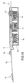
- eine Darstellung der Zahnbürste mit Griffteil gemäß Fig. 8 mit einem auf das Griffteil aufgeschobenes Gehäuse für Borstenköpfe,
- Fig. 11
- eine Seitenansicht des Gehäuses nach Fig. 10,
- Fig. 12
- einen Schnitt durch das Gehäuse gemäß Fig. 11,
- Fig. 13
- eine Draufsicht auf das Gehäuse gemäß Fig. 11 und
- Fig. 14
- eine Draufsicht auf eine das Gehäuse abdeckende Verschlußplatte.
- In den Zeichnungen ist eine Zahnbürste insgesamt mit der Bezugsziffer 10 bezeichnet.
- Die Zahnbürste 10 weist einen aus Federstahldraht bestehenden Korpus 11 auf, wobei als Federstahldraht ein nickelfreier V4A-Medizinstahl Verwendung findet. Der Korpus 11 ist in zwei unterschiedlich lange Schenkel 12 unterteilt, welche im aneinandergelegten Zustand ein Kopfteil 13 zur Aufnahme eines Borstenkopfes 14, einen Stiel 15 und zwei Schenkel-Endbereiche 16, die in einem Griffteil 17 lösbar verankert werden können, bilden. Im Übergang vom Stiel 15 zu den Schenkel-Endbereichen 16 ist in beiden Schenkeln 12 gegenüberliegend jeweils eine Feder 18 mit mehreren Windungen in den Federstahldraht eingeformt, deren Windungs-Mittelachsen w, ausgehend von einer Längsachse x der Zahnbürste 10, beidseitig schräg nach außen verlaufen. Ein zwischen der Längsachse x der Zahnbürste und den Windungs-Mittelachsen w angeordneter Winkel α kann bei unterschiedlichen Zahnbürsten 10 zwischen 0o und 90o betragen, je nachdem wie die Federeigenschaft und das Maß der Beweglichkeit des Kopfteils 13 sein sollen.
- Während der kürzere Schenkel-Endbereich 16 des Korpus 11 einen einfachen Versteifungsbogen 19 aufweist, ist der längere Schenkel-Endbereich 16 mit einem in Richtung zum Kopfteil 13 hin umgebogenen Federelement 20 sowie ebenfalls einem Versteifungsbogen 21 versehen. Der Versteifungsbogen 21 ist darüber hinaus mit einem aus der durch die Schenkel 12 aufgespannten Ebene herausragenden Bereich 22 versehen, dessen Funktion nachfolgend beschrieben wird.
- Der aus Federstahldraht bestehende Korpus 11 kann nach Einfügen eines in Fig. 4 dargestellten Borstenkopfes 14 mit seinen Schenkeln 12 aneinandergelegt in eine Führung 23 des Griffteils 17 eingeschoben werden. Der vorgenannte Bereich 22 dient dabei als Orientierungshilfe, da ein falsch orientiertes Einlegen des Korpus 11 durch den erhabenen Bereich 22 verhindert wird.
- Die Schenkel-Endbereiche 16 des Korpus 11 werden soweit in das Griffteil 17 eingeführt, bis daß - wie in Fig. 7 dargestellt - der Versteifungsbogen 21 des Federelementes 20 in einer Rastöffnung 24 im Griffteil 17 einrastet.
- Zum Zwecke des einfachen Einsetzens des Borstenkopfes 14 weist das Kopfteil 13 an den gegenüberliegenden Längsseiten 25 spiegelbildlich angeordnete Auskröpfungen 26 auf, welche mit entsprechenden Ausnehmungen 27 am Borstenkopf 14 zusammenwirken. Der Borstenkopf 14 wird im Endeffekt dadurch im Kopfteil 14 gehalten, daß der Federstahldraht des Korpus 11 in eine umlaufende Nut 28 am Borstenkopf 14 eingreift. Durch das Vorhandensein von Auskröpfungen 26 in Ausnehmungen 27 wird ein falsch orientiertes Einsetzen des Borstenkopfes 14 in das Kopfteil 13 zuverlässig verhindert.
- In Fig. 4 ist ein Borstenkopf 14 dargestellt, in dem abwechselnd jeweils eine Reihe kurzer und langer Borstenbündel verankert sind, welche aus Kunststoff bestehen. Während die kurzen Borstenbündel der Reinigung der Zahnoberflächen dienen, sollen die langen Borstenbündel die Zahnzwischenräume säubern.
- Wie insbesondere Fig. 9 zeigt, ist es durch ein fingerseitiges Herausdrücken des Versteifungsbogens 21 des Federelements 20 aus der Rastöffnung 24 des Griffteils 17 möglich, das Griffteil 17 teilweise von den Schenkel-Endbereichen 16 abzuziehen. Dabei rastet der Versteifungsbogen 21 in eine weitere im Bereich der Führungsschiene 23 angeordnete Rastöffnung 29 ein, wobei der kurze Schenkel-Endbereich 16 die Führungsschiene 23 verläßt, so daß aufgrund der dem Korpus 11 innewohnenden Federkraft die beiden Schenkel 12 auseinanderschwenken. In dieser Stellung wird der Borstenkopf 14 - wie hier nicht dargestellt - frei und es kann ein neuer Borstenkopf 14 eingesetzt werden.
- Zur Benutzung der zuvor beschriebenen Zahnbürste 10 wird das Griffteil 17 so von einer Hand umschlossen, daß der Daumen an einer am Griffteil 17 angeordneten Daumenabstützung D anliegt. Während der Betätigung der Zahnbürste 10 ist nicht nur eine Ausweichbewegung des Kopfteils 13 einschließlich des Borstenkopfes 14 in allen quer zu einer Längsachse x der Zahnbürste 10 verlaufenden Richtungen möglich, sondern auch eine Bewegung des Kopfteils 13 und des Stieles 14 in Richtung zum Griffteil 17. Durch diese Ausgleichsbewegungen kann nicht nur der Andruck der Zahnbürste 10 beim normalen Putzen der Zähne begrenzt werden, sondern es wird auch bei ruckartigen Bewegungen der Hand bzw. des Kopfes eine Verletzung der Zähne bzw. des Zahnfleisches verhindert. Während die quer zur Längserstreckung x der Zahnbürste 10 verlaufenden Ausweichbewegungen einerseits durch die Verwendung von Federstahldraht und andererseits durch die Einformung von schräg zur Längsachse x orientierten, gegenüberliegenden Federn 18 sowie der freien Bewegbarkeit des kurzen Schenkel-Endbereichs 16 ermöglicht wird, ist die federnde Relativbewegung von Kopfteil 13 und Griffteil 17 durch den als Federelement 20 ausgebildeten, längeren Schenkel-Endbereich 16 erzielbar.
- Wie in der Fig. 10 dargestellt, ist die Zahnbürste 10 auch mit einem Gehäuse 30 dadurch verbindbar, daß das Griffteil 17 in eine dem Gehäuse 30 vorgesehene Führung 31 eingeschoben wird. Das in der Fig. 10 dargestellte Gehäuse 30 dient als Aufbewahrungsraum für die Borstenköpfe 14, als Wandhalter für die Zahnbürste 10 und als Verkaufsverpackung, wobei die Aufhängung der Zahnbürste 10 einschließlich Gehäuse 30 mittels einer aus dem Gehäuse 30 herausragenden, durch das Federelement 20 gebildete Öse 36 möglich ist (s. Fig. 7 und 10).
- Das Gehäuse 30 kann jedoch auch durch eine Verschlußplatte 32 abgedeckt sein, in der eine der Wandbefestigung dienende Öffnung 33 vorhanden ist. Die Verschlußplatte 32 wird ebenfalls in die Führung 31 eingeschoben und durch das Zusammenwirken von Arretierungsschlitzen 34 im Gehäuse 30 und an der Verschlußplatte vorhandenen Arretierungsvorsprüngen 35 mit dem Gehäuse 30 verrastet.
Claims (11)
- Zahnbürste mit einem beim Zähneputzen unter Belastung zumindest teilbeweglichen Kopfteil, in dem ein auswechselbarer Borstenkopf angeordnet ist, einem Stiel und einem Griffteil, dadurch gekennzeichnet, daß das Kopfteil (13) und der Stiel (15) der Zahnbürste (10) aus einem durchgehenden, aus zwei Schenkeln (12) bestehenden Federstahldraht geformt ist, dessen Schenkel (12) im Bereich des Stiels (15) jeweils eine Feder (18) mit einer Mehrzahl von Windungen aufweisen, welche Bewegungen des Kopfteils (13) in alle Richtungen quer zur Längsachse (x) der Zahnbürste (10) ermöglichen, und daß der Borstenkopf (14) im Kopfteil (13) durch das Zusammenführen und die lösbare Befestigung von Endbereichen (16) der Schenkel (12) im Griffteil (17) verklemmbar ist.
- Zahnbürste nach Anspruch 1, dadurch gekennzeichnet, daß die gegenüberliegenden in den Schenkeln (12) eingeformten Federn (18) jeweils eine Windungs-Mittelachse (w) aufweisen, die ausgehend von einer Längsachse (x) der Zahnbürste (10) schräg nach außen verläuft.
- Zahnbürste nach Anspruch 1 oder 2, dadurch gekennzeichnet, daß wenigstens ein Schenkel-Endbereich (16) in Richtung der Längsachse (x) der Zahnbürste (10) verschiebbar im Griffteil (17) gelagert ist.
- Zahnbürste nach einem der Ansprüche 1 bis 3, dadurch gekennzeichnet, daß die Schenkel-Endbereiche (16) mit einem im Griffteil (17) angeordneten Elektroantrieb bewegungsverbunden sind, durch den die Schenkel (12) in Schwingungen versetzbar sind.
- Zahnbürste nach einem der Ansprüche 1 bis 4, dadurch gekennzeichnet, daß beide Schenkel-Endbereiche (16) im Griffteil (17) in Längsachsrichtung (x) der Zahnbürste (10) teilbewegbar gelagert sind, und daß sich die Schenkel (12) beim Einwirken einer Kraft auf das Kopfteil (13) entgegen einer Federkraft teilweise in das Griffteil (17) einschieben.
- Zahnbürste nach einem der vorhergehenden Ansprüche, dadurch gekennzeichnet, daß der Griffteil (10) eine Führungsschiene (23) aufweist, die mit Rastöffnungen (24, 29) für mindestens einen Schenkel-Endbereich (16) versehen ist.
- Zahnbürste nach einem der vorhergehenden Ansprüche, dadurch gekennzeichnet, daß wenigstens ein Schenkel-Endbereich (16) mit einem Federelement (20) versehen ist und im gespannten Zustand in der Rastöffnung (24) des Griffteils (17) angeordnet ist.
- Zahnbürste nach einem der vorhergehenden Ansprüche, dadurch gekennzeichnet, daß sämtliche Teile (11, 17) der Zahnbürste (10) mit Ausnahme des Borstenkopfes (14) aus V4A-Medizinstahl bestehen.
- Zahnbürste nach einem der vorhergehenden Ansprüche, dadurch gekennzeichnet, daß das Griffteil (17) mitsamt den Schenkel-Endbereichen (16) in ein Gehäuse (30) einschiebbar ist, welches als Wandhalter für die Zahnbürste und als Stauraum für Borstenköpfe (14) dient.
- Zahnbürste nach einem der vorhergehenden Ansprüche, dadurch gekennzeichnet, daß kopfteilseitig am Griffteil (17) eine Daumenabstützung (D) angeordnet ist.
- Zahnbürste nach einem der vorhergehenden Ansprüche, dadurch gekennzeichnet, daß der Federstahldraht auf jeder Seite des Kopfteils (13) eine Auskröpfung (26) aufweist, die zur richtigen Orientierung des Borstenkopfes (14) jeweils mit einer entsprechenden Ausnehmung (27) am Borstenkopf (14) zusammenwirkt.
Applications Claiming Priority (2)
| Application Number | Priority Date | Filing Date | Title |
|---|---|---|---|
| DE4410003A DE4410003C1 (de) | 1994-03-23 | 1994-03-23 | Zahnbürste |
| DE4410003 | 1994-03-23 |
Publications (2)
| Publication Number | Publication Date |
|---|---|
| EP0688517A1 true EP0688517A1 (de) | 1995-12-27 |
| EP0688517B1 EP0688517B1 (de) | 1996-10-30 |
Family
ID=6513613
Family Applications (1)
| Application Number | Title | Priority Date | Filing Date |
|---|---|---|---|
| EP95101274A Expired - Lifetime EP0688517B1 (de) | 1994-03-23 | 1995-01-31 | Zahnbürste |
Country Status (13)
| Country | Link |
|---|---|
| US (2) | US5598599A (de) |
| EP (1) | EP0688517B1 (de) |
| JP (1) | JPH07275035A (de) |
| CN (1) | CN1120422A (de) |
| AT (1) | ATE144690T1 (de) |
| AU (1) | AU1531795A (de) |
| DE (2) | DE4410003C1 (de) |
| DK (1) | DK0688517T3 (de) |
| ES (1) | ES2095169T3 (de) |
| GR (1) | GR3022254T3 (de) |
| TR (1) | TR28453A (de) |
| WO (1) | WO1995025450A1 (de) |
| ZA (1) | ZA951695B (de) |
Families Citing this family (16)
| Publication number | Priority date | Publication date | Assignee | Title |
|---|---|---|---|---|
| US5462784A (en) * | 1994-11-02 | 1995-10-31 | International Business Machines Corporation | Fluorinated diamond-like carbon protective coating for magnetic recording media devices |
| US5901404A (en) * | 1997-07-02 | 1999-05-11 | Lin; Chung Sing | Brush and container assembly |
| DE29820734U1 (de) * | 1998-11-20 | 2000-03-23 | M + C Schiffer GmbH, 53577 Neustadt | Bürste, insbesondere Zahnbürste |
| US7178191B2 (en) * | 2003-01-14 | 2007-02-20 | Jeffrey Davis Hitzler | Paint brush with angle adjustable handle |
| USD536876S1 (en) | 2003-02-03 | 2007-02-20 | Church & Dwight Co., Inc. | Head portion of a toothbrush |
| US7398575B2 (en) * | 2004-02-17 | 2008-07-15 | Church & Dwight Co., Inc. | Electric toothbrush having a flexible drive shaft |
| US7665171B2 (en) * | 2006-10-06 | 2010-02-23 | Fna Ip Holdings, Inc. | Water-operated wash brush with removable brush head |
| RU2428907C2 (ru) | 2007-02-02 | 2011-09-20 | Дзе Жиллетт Компани | Принадлежности для гигиены полости рта, имеющие гибкие элементы, и способы их изготовления |
| KR100959932B1 (ko) * | 2008-05-09 | 2010-05-26 | 주식회사 엘지생활건강 | 칫솔 |
| WO2010068352A1 (en) * | 2008-12-11 | 2010-06-17 | Farzana Ayubi Afghan | Sanitary toothbrush and holder apparatus |
| IL196650A (en) | 2009-01-22 | 2015-06-30 | Mordechai Kirsh | Toothbrush |
| BR112013005086B1 (pt) * | 2010-09-20 | 2020-12-15 | The Gillette Company Llc | Escova de dentes manual |
| US20120324664A1 (en) * | 2011-06-24 | 2012-12-27 | Don Allen Carpenter | Flexible toothbrush with rigid handle support |
| CN102525101A (zh) * | 2012-03-12 | 2012-07-04 | 张利民 | 卡簧式换头牙刷 |
| CN103876453A (zh) * | 2012-12-24 | 2014-06-25 | 王文林 | 弹性刷架更换刷头的牙刷及制造方法 |
| KR101804482B1 (ko) * | 2016-03-24 | 2017-12-04 | 김재찬 | 칫솔모 헤드 교체 가능한 칫솔 |
Citations (4)
| Publication number | Priority date | Publication date | Assignee | Title |
|---|---|---|---|---|
| GB366460A (en) * | 1929-10-08 | 1932-02-04 | Antoine Deloire | Improvements in tooth brushes |
| US2226814A (en) * | 1939-06-08 | 1940-12-31 | Harold E Gregg | Toothbrush handle |
| GB544870A (en) * | 1941-06-10 | 1942-04-30 | Norman Proudlove | Improvements in brushes and mops |
| CH247968A (de) * | 1946-03-26 | 1947-04-15 | Fortschritt Patent Verwertungs | Bürste mit stielartigem Griff. |
Family Cites Families (14)
| Publication number | Priority date | Publication date | Assignee | Title |
|---|---|---|---|---|
| US759490A (en) * | 1902-12-08 | 1904-05-10 | Florence Mfg Company | Tooth-brush. |
| US1241881A (en) * | 1916-12-14 | 1917-10-02 | Alphonse Arthur Picard | Brush. |
| US3174174A (en) * | 1963-06-17 | 1965-03-23 | Dengler Rudolf | Tooth brush with disposable head |
| US3229318A (en) * | 1964-05-15 | 1966-01-18 | Sunbeam Corp | Toothbrush |
| US4333199A (en) * | 1980-02-22 | 1982-06-08 | Rosario M Del | Toothbrush |
| US4488328A (en) * | 1983-01-24 | 1984-12-18 | Hyman Richard M | Floating head toothbrush |
| DE3345605A1 (de) * | 1983-12-16 | 1985-06-20 | Mathias Otto 1000 Berlin Barth | Neuartige zahnbuerste |
| US4890732A (en) * | 1988-03-18 | 1990-01-02 | Shackelford Renee M F | Apparatus for brushing teeth with hygienic disposable bristles |
| DE3923495C1 (de) * | 1989-07-15 | 1991-01-24 | M + C Schiffer Gmbh, 5466 Neustadt, De | |
| DE4019313C1 (de) * | 1990-06-16 | 1991-08-29 | Robert 4350 Recklinghausen De Heuckmann | |
| US5146645A (en) * | 1991-03-01 | 1992-09-15 | The Procter & Gamble Company | Toothbrush employing resiliently buckling arch to indicate excessive brushing pressure |
| US5144712A (en) * | 1991-05-06 | 1992-09-08 | Hansel Gail W | Disposable toothbrush |
| GB2255901B (en) * | 1991-05-21 | 1995-07-19 | Appealing Appliances Co Ltd | Electric toothbrush holder |
| US5373702A (en) * | 1993-07-12 | 1994-12-20 | Minnesota Valley Engineering, Inc. | LNG delivery system |
-
1994
- 1994-03-23 DE DE4410003A patent/DE4410003C1/de not_active Expired - Fee Related
-
1995
- 1995-01-28 AU AU15317/95A patent/AU1531795A/en not_active Abandoned
- 1995-01-28 WO PCT/DE1995/000118 patent/WO1995025450A1/de not_active Ceased
- 1995-01-31 DE DE59500035T patent/DE59500035D1/de not_active Expired - Lifetime
- 1995-01-31 DK DK95101274.9T patent/DK0688517T3/da active
- 1995-01-31 AT AT95101274T patent/ATE144690T1/de active
- 1995-01-31 EP EP95101274A patent/EP0688517B1/de not_active Expired - Lifetime
- 1995-01-31 ES ES95101274T patent/ES2095169T3/es not_active Expired - Lifetime
- 1995-03-01 ZA ZA951695A patent/ZA951695B/xx unknown
- 1995-03-07 JP JP7084420A patent/JPH07275035A/ja active Pending
- 1995-03-20 CN CN95102704A patent/CN1120422A/zh active Pending
- 1995-03-22 US US08/408,850 patent/US5598599A/en not_active Expired - Fee Related
- 1995-03-23 TR TR00308/95A patent/TR28453A/xx unknown
-
1996
- 1996-07-19 US US08/684,939 patent/US5692260A/en not_active Expired - Fee Related
-
1997
- 1997-01-09 GR GR970400021T patent/GR3022254T3/el unknown
Patent Citations (4)
| Publication number | Priority date | Publication date | Assignee | Title |
|---|---|---|---|---|
| GB366460A (en) * | 1929-10-08 | 1932-02-04 | Antoine Deloire | Improvements in tooth brushes |
| US2226814A (en) * | 1939-06-08 | 1940-12-31 | Harold E Gregg | Toothbrush handle |
| GB544870A (en) * | 1941-06-10 | 1942-04-30 | Norman Proudlove | Improvements in brushes and mops |
| CH247968A (de) * | 1946-03-26 | 1947-04-15 | Fortschritt Patent Verwertungs | Bürste mit stielartigem Griff. |
Also Published As
| Publication number | Publication date |
|---|---|
| DK0688517T3 (da) | 1996-11-25 |
| EP0688517B1 (de) | 1996-10-30 |
| ES2095169T3 (es) | 1997-02-01 |
| DE4410003C1 (de) | 1995-03-16 |
| US5692260A (en) | 1997-12-02 |
| CN1120422A (zh) | 1996-04-17 |
| US5598599A (en) | 1997-02-04 |
| ZA951695B (en) | 1995-12-11 |
| JPH07275035A (ja) | 1995-10-24 |
| AU1531795A (en) | 1995-10-09 |
| GR3022254T3 (en) | 1997-04-30 |
| DE59500035D1 (de) | 1996-12-05 |
| TR28453A (tr) | 1996-07-01 |
| ATE144690T1 (de) | 1996-11-15 |
| WO1995025450A1 (de) | 1995-09-28 |
Similar Documents
| Publication | Publication Date | Title |
|---|---|---|
| DE69229796T2 (de) | Selbsteinstellbare dreiseitige zahnbürste | |
| EP0704179B1 (de) | Zahnbürste | |
| EP0688517B1 (de) | Zahnbürste | |
| DE69635847T2 (de) | Zahnbürste | |
| DE69221722T2 (de) | Handbetätigte, rotierbare zahnbürste | |
| DE2652744C2 (de) | Zahnbürste | |
| DE69916346T2 (de) | Bürste zum Auftragen von Schminke, damit ausgerüstete Vorrichtung und Herstellungsverfahren | |
| EP1069846A1 (de) | Reinigungsbürste, insbesondere zahnbürste | |
| CH661418A5 (de) | Zahnbuerste. | |
| DE10360102A1 (de) | Handzahnbürste | |
| EP1121034A1 (de) | Bürste, insbesondere zahnbürste | |
| DE19538569A1 (de) | Borstenware mit verstellbarer Borstenhärte | |
| EP1277420B1 (de) | Zahnbürste | |
| EP0550818A1 (de) | Halteorgan an einem Griff und Dentalbürste zum auswechselbaren Befestigen an einer Halterung | |
| WO1996027308A1 (de) | Borstenware wie bürste, pinsel od. dgl. | |
| DE102007018766A1 (de) | Zahnbürste | |
| EP0449152A1 (de) | Gerät zum Reinigen von Zähnen und/oder Zahnzwischenräumen | |
| DE60127283T2 (de) | Zahnseidenhalter | |
| DE68916949T2 (de) | Zahnreinigungsanordnung. | |
| DE69109511T2 (de) | Halteschaft für eine Interdentalzahnbürste. | |
| DE4234764A1 (de) | Die knopflose Einrastverbindung für die den Handgriff aufweisenden und teilbaren Vorrichtungen, für die Bürsten und insbesondere für die Zahnbürsten | |
| DE212018000325U1 (de) | Vorrichtung zum Reinigen von Zahnzwischenräumen | |
| WO2019037879A1 (de) | Interdentalbürste | |
| DE202009012010U1 (de) | Interdentalbürste | |
| AT503725B1 (de) | Interdentalbürsteneinrichtung |
Legal Events
| Date | Code | Title | Description |
|---|---|---|---|
| PUAI | Public reference made under article 153(3) epc to a published international application that has entered the european phase |
Free format text: ORIGINAL CODE: 0009012 |
|
| 17P | Request for examination filed |
Effective date: 19950711 |
|
| AK | Designated contracting states |
Kind code of ref document: A1 Designated state(s): AT BE CH DE DK ES FR GB GR IE IT LI LU NL PT SE |
|
| GRAG | Despatch of communication of intention to grant |
Free format text: ORIGINAL CODE: EPIDOS AGRA |
|
| GRAH | Despatch of communication of intention to grant a patent |
Free format text: ORIGINAL CODE: EPIDOS IGRA |
|
| ITF | It: translation for a ep patent filed | ||
| GRAH | Despatch of communication of intention to grant a patent |
Free format text: ORIGINAL CODE: EPIDOS IGRA |
|
| GRAA | (expected) grant |
Free format text: ORIGINAL CODE: 0009210 |
|
| AK | Designated contracting states |
Kind code of ref document: B1 Designated state(s): AT BE CH DK ES FR GB GR IE IT LI LU NL PT SE |
|
| AX | Request for extension of the european patent |
Free format text: LT PAYMENT 950213;SI PAYMENT 950213 |
|
| RAX | Requested extension states of the european patent have changed |
Free format text: LT PAYMENT 950213;SI PAYMENT 950213 |
|
| REF | Corresponds to: |
Ref document number: 144690 Country of ref document: AT Date of ref document: 19961115 Kind code of ref document: T |
|
| GBT | Gb: translation of ep patent filed (gb section 77(6)(a)/1977) |
Effective date: 19961030 |
|
| REG | Reference to a national code |
Ref country code: DK Ref legal event code: T3 |
|
| ET | Fr: translation filed | ||
| REF | Corresponds to: |
Ref document number: 59500035 Country of ref document: DE Date of ref document: 19961205 |
|
| REG | Reference to a national code |
Ref country code: IE Ref legal event code: FG4D Free format text: 70510 |
|
| RBV | Designated contracting states (corrected) |
Designated state(s): AT BE CH DK ES FR GB GR IE IT LI LU NL PT SE |
|
| REG | Reference to a national code |
Ref country code: CH Ref legal event code: NV Representative=s name: MOINAS KIEHL SAVOYE & CRONIN |
|
| REG | Reference to a national code |
Ref country code: ES Ref legal event code: FG2A Ref document number: 2095169 Country of ref document: ES Kind code of ref document: T3 |
|
| REG | Reference to a national code |
Ref country code: PT Ref legal event code: SC4A Free format text: AVAILABILITY OF NATIONAL TRANSLATION Effective date: 19961031 |
|
| REG | Reference to a national code |
Ref country code: GR Ref legal event code: FG4A Free format text: 3022254 |
|
| REG | Reference to a national code |
Ref country code: DE Ref legal event code: 8566 |
|
| PLBE | No opposition filed within time limit |
Free format text: ORIGINAL CODE: 0009261 |
|
| STAA | Information on the status of an ep patent application or granted ep patent |
Free format text: STATUS: NO OPPOSITION FILED WITHIN TIME LIMIT |
|
| 26N | No opposition filed | ||
| PGFP | Annual fee paid to national office [announced via postgrant information from national office to epo] |
Ref country code: PT Payment date: 20000120 Year of fee payment: 6 |
|
| PGFP | Annual fee paid to national office [announced via postgrant information from national office to epo] |
Ref country code: DK Payment date: 20000125 Year of fee payment: 6 |
|
| PGFP | Annual fee paid to national office [announced via postgrant information from national office to epo] |
Ref country code: BE Payment date: 20000126 Year of fee payment: 6 |
|
| PGFP | Annual fee paid to national office [announced via postgrant information from national office to epo] |
Ref country code: LU Payment date: 20000127 Year of fee payment: 6 Ref country code: AT Payment date: 20000127 Year of fee payment: 6 |
|
| PGFP | Annual fee paid to national office [announced via postgrant information from national office to epo] |
Ref country code: IE Payment date: 20000128 Year of fee payment: 6 Ref country code: CH Payment date: 20000128 Year of fee payment: 6 |
|
| PGFP | Annual fee paid to national office [announced via postgrant information from national office to epo] |
Ref country code: NL Payment date: 20000131 Year of fee payment: 6 Ref country code: GR Payment date: 20000131 Year of fee payment: 6 |
|
| PGFP | Annual fee paid to national office [announced via postgrant information from national office to epo] |
Ref country code: SE Payment date: 20010125 Year of fee payment: 7 Ref country code: GB Payment date: 20010125 Year of fee payment: 7 |
|
| PGFP | Annual fee paid to national office [announced via postgrant information from national office to epo] |
Ref country code: ES Payment date: 20010129 Year of fee payment: 7 |
|
| PG25 | Lapsed in a contracting state [announced via postgrant information from national office to epo] |
Ref country code: LU Free format text: LAPSE BECAUSE OF NON-PAYMENT OF DUE FEES Effective date: 20010131 Ref country code: LI Free format text: LAPSE BECAUSE OF NON-PAYMENT OF DUE FEES Effective date: 20010131 Ref country code: IE Free format text: LAPSE BECAUSE OF NON-PAYMENT OF DUE FEES Effective date: 20010131 Ref country code: GR Free format text: LAPSE BECAUSE OF NON-PAYMENT OF DUE FEES Effective date: 20010131 Ref country code: DK Free format text: LAPSE BECAUSE OF NON-PAYMENT OF DUE FEES Effective date: 20010131 Ref country code: CH Free format text: LAPSE BECAUSE OF NON-PAYMENT OF DUE FEES Effective date: 20010131 Ref country code: BE Free format text: LAPSE BECAUSE OF NON-PAYMENT OF DUE FEES Effective date: 20010131 Ref country code: AT Free format text: LAPSE BECAUSE OF NON-PAYMENT OF DUE FEES Effective date: 20010131 |
|
| PGFP | Annual fee paid to national office [announced via postgrant information from national office to epo] |
Ref country code: FR Payment date: 20010131 Year of fee payment: 7 |
|
| BERE | Be: lapsed |
Owner name: HAIDUK HERBERT Effective date: 20010131 |
|
| PG25 | Lapsed in a contracting state [announced via postgrant information from national office to epo] |
Ref country code: PT Free format text: LAPSE BECAUSE OF NON-PAYMENT OF DUE FEES Effective date: 20010731 |
|
| PG25 | Lapsed in a contracting state [announced via postgrant information from national office to epo] |
Ref country code: NL Free format text: LAPSE BECAUSE OF NON-PAYMENT OF DUE FEES Effective date: 20010801 |
|
| REG | Reference to a national code |
Ref country code: CH Ref legal event code: PL |
|
| REG | Reference to a national code |
Ref country code: DK Ref legal event code: EBP |
|
| NLV4 | Nl: lapsed or anulled due to non-payment of the annual fee |
Effective date: 20010801 |
|
| REG | Reference to a national code |
Ref country code: IE Ref legal event code: MM4A |
|
| REG | Reference to a national code |
Ref country code: PT Ref legal event code: MM4A Free format text: LAPSE DUE TO NON-PAYMENT OF FEES Effective date: 20010731 |
|
| REG | Reference to a national code |
Ref country code: GB Ref legal event code: IF02 |
|
| PG25 | Lapsed in a contracting state [announced via postgrant information from national office to epo] |
Ref country code: GB Free format text: LAPSE BECAUSE OF NON-PAYMENT OF DUE FEES Effective date: 20020131 |
|
| PG25 | Lapsed in a contracting state [announced via postgrant information from national office to epo] |
Ref country code: SE Free format text: LAPSE BECAUSE OF NON-PAYMENT OF DUE FEES Effective date: 20020201 Ref country code: ES Free format text: LAPSE BECAUSE OF NON-PAYMENT OF DUE FEES Effective date: 20020201 |
|
| GBPC | Gb: european patent ceased through non-payment of renewal fee |
Effective date: 20020131 |
|
| EUG | Se: european patent has lapsed |
Ref document number: 95101274.9 |
|
| PG25 | Lapsed in a contracting state [announced via postgrant information from national office to epo] |
Ref country code: FR Free format text: LAPSE BECAUSE OF NON-PAYMENT OF DUE FEES Effective date: 20020930 |
|
| REG | Reference to a national code |
Ref country code: FR Ref legal event code: ST |
|
| REG | Reference to a national code |
Ref country code: ES Ref legal event code: FD2A Effective date: 20030211 |
|
| PG25 | Lapsed in a contracting state [announced via postgrant information from national office to epo] |
Ref country code: IT Free format text: LAPSE BECAUSE OF NON-PAYMENT OF DUE FEES;WARNING: LAPSES OF ITALIAN PATENTS WITH EFFECTIVE DATE BEFORE 2007 MAY HAVE OCCURRED AT ANY TIME BEFORE 2007. THE CORRECT EFFECTIVE DATE MAY BE DIFFERENT FROM THE ONE RECORDED. Effective date: 20050131 |