EP0688531A1 - Débitmètre électromagnétique - Google Patents
Débitmètre électromagnétique Download PDFInfo
- Publication number
- EP0688531A1 EP0688531A1 EP95304314A EP95304314A EP0688531A1 EP 0688531 A1 EP0688531 A1 EP 0688531A1 EP 95304314 A EP95304314 A EP 95304314A EP 95304314 A EP95304314 A EP 95304314A EP 0688531 A1 EP0688531 A1 EP 0688531A1
- Authority
- EP
- European Patent Office
- Prior art keywords
- pair
- lumen
- magnetic poles
- conduit
- electrodes
- Prior art date
- Legal status (The legal status is an assumption and is not a legal conclusion. Google has not performed a legal analysis and makes no representation as to the accuracy of the status listed.)
- Withdrawn
Links
- 239000004020 conductor Substances 0.000 claims abstract description 7
- 239000003146 anticoagulant agent Substances 0.000 claims description 14
- 229940127219 anticoagulant drug Drugs 0.000 claims description 14
- 238000004519 manufacturing process Methods 0.000 claims description 8
- 239000012530 fluid Substances 0.000 claims description 7
- 239000000463 material Substances 0.000 description 9
- 230000004907 flux Effects 0.000 description 6
- 239000008280 blood Substances 0.000 description 5
- 210000004369 blood Anatomy 0.000 description 5
- 238000000034 method Methods 0.000 description 4
- 238000010276 construction Methods 0.000 description 3
- 238000010586 diagram Methods 0.000 description 3
- 239000012778 molding material Substances 0.000 description 3
- 229920005989 resin Polymers 0.000 description 3
- 239000011347 resin Substances 0.000 description 3
- 239000000853 adhesive Substances 0.000 description 2
- 230000001070 adhesive effect Effects 0.000 description 2
- 230000003247 decreasing effect Effects 0.000 description 2
- 230000000694 effects Effects 0.000 description 2
- 230000005284 excitation Effects 0.000 description 2
- 238000007689 inspection Methods 0.000 description 2
- 238000000465 moulding Methods 0.000 description 2
- 239000004033 plastic Substances 0.000 description 2
- 230000008569 process Effects 0.000 description 2
- 229920003319 Araldite® Polymers 0.000 description 1
- HTTJABKRGRZYRN-UHFFFAOYSA-N Heparin Chemical compound OC1C(NC(=O)C)C(O)OC(COS(O)(=O)=O)C1OC1C(OS(O)(=O)=O)C(O)C(OC2C(C(OS(O)(=O)=O)C(OC3C(C(O)C(O)C(O3)C(O)=O)OS(O)(=O)=O)C(CO)O2)NS(O)(=O)=O)C(C(O)=O)O1 HTTJABKRGRZYRN-UHFFFAOYSA-N 0.000 description 1
- 230000004075 alteration Effects 0.000 description 1
- 229910000963 austenitic stainless steel Inorganic materials 0.000 description 1
- 210000004204 blood vessel Anatomy 0.000 description 1
- 230000008859 change Effects 0.000 description 1
- 238000000748 compression moulding Methods 0.000 description 1
- 238000001125 extrusion Methods 0.000 description 1
- 229960002897 heparin Drugs 0.000 description 1
- 229920000669 heparin Polymers 0.000 description 1
- 238000001746 injection moulding Methods 0.000 description 1
- 239000000696 magnetic material Substances 0.000 description 1
- 238000005259 measurement Methods 0.000 description 1
- 239000004417 polycarbonate Substances 0.000 description 1
- 229920000515 polycarbonate Polymers 0.000 description 1
- 238000011160 research Methods 0.000 description 1
- 239000002904 solvent Substances 0.000 description 1
- 238000005507 spraying Methods 0.000 description 1
- 229910001220 stainless steel Inorganic materials 0.000 description 1
- 238000006467 substitution reaction Methods 0.000 description 1
- 238000001356 surgical procedure Methods 0.000 description 1
Images




Classifications
-
- A—HUMAN NECESSITIES
- A61—MEDICAL OR VETERINARY SCIENCE; HYGIENE
- A61B—DIAGNOSIS; SURGERY; IDENTIFICATION
- A61B5/00—Measuring for diagnostic purposes; Identification of persons
- A61B5/02—Detecting, measuring or recording for evaluating the cardiovascular system, e.g. pulse, heart rate, blood pressure or blood flow
- A61B5/026—Measuring blood flow
- A61B5/0265—Measuring blood flow using electromagnetic means, e.g. electromagnetic flowmeter
-
- G—PHYSICS
- G01—MEASURING; TESTING
- G01F—MEASURING VOLUME, VOLUME FLOW, MASS FLOW OR LIQUID LEVEL; METERING BY VOLUME
- G01F1/00—Measuring the volume flow or mass flow of fluid or fluent solid material wherein the fluid passes through a meter in a continuous flow
- G01F1/56—Measuring the volume flow or mass flow of fluid or fluent solid material wherein the fluid passes through a meter in a continuous flow by using electric or magnetic effects
- G01F1/58—Measuring the volume flow or mass flow of fluid or fluent solid material wherein the fluid passes through a meter in a continuous flow by using electric or magnetic effects by electromagnetic flowmeters
- G01F1/584—Measuring the volume flow or mass flow of fluid or fluent solid material wherein the fluid passes through a meter in a continuous flow by using electric or magnetic effects by electromagnetic flowmeters constructions of electrodes, accessories therefor
-
- G—PHYSICS
- G01—MEASURING; TESTING
- G01F—MEASURING VOLUME, VOLUME FLOW, MASS FLOW OR LIQUID LEVEL; METERING BY VOLUME
- G01F1/00—Measuring the volume flow or mass flow of fluid or fluent solid material wherein the fluid passes through a meter in a continuous flow
- G01F1/56—Measuring the volume flow or mass flow of fluid or fluent solid material wherein the fluid passes through a meter in a continuous flow by using electric or magnetic effects
- G01F1/58—Measuring the volume flow or mass flow of fluid or fluent solid material wherein the fluid passes through a meter in a continuous flow by using electric or magnetic effects by electromagnetic flowmeters
- G01F1/586—Measuring the volume flow or mass flow of fluid or fluent solid material wherein the fluid passes through a meter in a continuous flow by using electric or magnetic effects by electromagnetic flowmeters constructions of coils, magnetic circuits, accessories therefor
-
- G—PHYSICS
- G01—MEASURING; TESTING
- G01F—MEASURING VOLUME, VOLUME FLOW, MASS FLOW OR LIQUID LEVEL; METERING BY VOLUME
- G01F1/00—Measuring the volume flow or mass flow of fluid or fluent solid material wherein the fluid passes through a meter in a continuous flow
- G01F1/56—Measuring the volume flow or mass flow of fluid or fluent solid material wherein the fluid passes through a meter in a continuous flow by using electric or magnetic effects
- G01F1/58—Measuring the volume flow or mass flow of fluid or fluent solid material wherein the fluid passes through a meter in a continuous flow by using electric or magnetic effects by electromagnetic flowmeters
- G01F1/60—Circuits therefor
Definitions
- This invention relates to an electromagnetic flowmeter.
- Electromagnetic flowmeters using a disposable conduit for passing blood therethrough are disclosed in U.S. Pat. Nos. 4,118,981, 4,195,515, 4,881,413 and JP-A-4 (1992)-324320.
- the conduit includes a conduit body constructed of a resin, a pair of electrodes to receive signals, and a pair of ground electrodes, arranged along the lumen at a specified distance from the pair of signal electrodes.
- the present inventor researches to improve the prior-art flowmeters and came up against the following problem.
- a pair of magnetic poles to apply a magnetic field to the lumen are inserted into the conduit body from outside, so that there invariably exists the material of the conduit body between the lumen and the poles of the electromagnet.
- the magnetic reluctance of the magnetic circuit is made unnecessarily large.
- the object of the present invention is to solve at least one of the above-mentioned problems.
- the pair of the poles of the electromagnet are each partly exposed to the lumen.
- the exposed portions preferably terminate flush with the surface of the lumen.
- this magnetic pole serves also as the ground electrode, so that the ground electrode which conventionally needed to be provided can be omitted.
- the pair of magnetic poles arranged as described are positioned most closely to each other, and accordingly the magnetic flux density distribution in the lumen becomes desirable, making it possible to measure the flow rate with high accuracy.
- the magnetic poles are exposed to the lumen, and to secure the sealability between the magnetic poles and the conduit body, the magnetic poles are inserted previously with high air-tightness. Therefore, the magnetic poles are made as discrete components to form a magnetic path, which are separate from other magnetic-path components, such as the yokes in the clamp to hold the conduit. Thus, the magnetic poles and the yokes are detachable.
- one end of each magnetic pole is formed in a circular cone which protrudes from the conduit body, while a cavity is formed in the yoke to receive the protruding cone.
- Another object of the present invention is to improve the accuracy of measurement.
- the yokes are formed by an electrically conductive and magnetic material. Under the condition that the conduit is mounted in the clamp, that is, the conduit is held by the clamp, the electrodes and the magnetic poles are enclosed by the yokes. Thus, electrodes of acquiring signals, electrodes of grounding and leads therefrom are shielded from outer electrostatic noise and electromagnetic noise.
- the present invention includes a method of manufacturing a conduit for passing blood therethrough.
- a conduit body is formed and then a film of anticoagulant is formed on the surface of the lumen.
- the molding material of the conduit body is not specified if it is electrically insulating, and a manufacturing method may be selected at discretion according to the kind of molding material. For example, if the conduit body is molded out of a resin, injection molding, compression molding or the like is selected. In molding the conduit body, holes into which the electrodes and the magnetic poles are inserted are formed at the same time. It is also possible to form a tubular material by extrusion molding, cut the tubular material into conduit bodies with an adequate, uniform length, and subsequently bore the holes in the conduit bodies.
- the film of anticoagulant is formed by immersing the conduit body in an anticoagulant, or applying or spraying an anticoagulant to the conduit body or by using any other known method.
- the electrodes and the magnetic poles coated with an adhesive are force-fitted into the holes of the conduit body to thereby secure the sealability between the conduit body and the electrodes and magnetic poles.
- the anticoagulant film does not exist on the surfaces of the electrodes and magnetic poles which are exposed to the lumen. Therefore, the impedance between the fluid flowing through the lumen, and the electrodes and the magnetic poles serving as the ground electrodes is not affected by the anticoagulant in the least. Needless to say, since the areas of the exposed surfaces of the electrodes and the magnetic poles are very small, even though they are not covered with the anticoagulant, they have hardly any influence on the blood.
- the film of anticoagulant is formed on the walls of the lumen after the electrodes and magnetic poles have been mounted to the conduit body, it is necessary to take some measures to prevent the film from being formed on the surfaces of the electrodes and magnetic poles exposed to the lumen.
- the anticoagulant is dissolved in a solvent medium which has an extremely poor wettability to the molding material of the electrodes and magnetic poles, but has a good wettability to the walls of the lumen, and then the anticoagulant is applied to the walls of the lumen.
- reference numeral 1 denotes a conduit including a conduit body 2 formed by a plastic material, a pair of signal electrodes 3, 3 inserted into the conduit body 2, and a pair of magnetic poles 4, 4 inserted into the conduit body 2 and serving also as ground electrodes.
- the conduit body 2 has a lumen 5 of a circular cross section passing in the longitudinal direction thereof.
- Reference numeral 6 denotes a lumen flow path to which the signal electrodes 3, 3 are exposed.
- the axis of the lumen 5, the axial direction of the signal electrodes 3, 3 and the axial direction of the magnetic poles 4, 4 serving also as the ground electrodes are mutually perpendicular to each other.
- Reference numerals 7, 8 denote L-shaped magnetic cores having coils 9, 10 respectively wound thereon, and the cores 7, 8 and coils 9, 10 form exciting means 11.
- the cores 7, 8 are connected with one-end portions thereof put together, and the magnetic cores 4, 4 are fitted in the cavities at the other-end portions 7b, 8b.
- the extreme ends of the magnetic cores 4, 4 are exposed to the lumen 5(6) passing through the conduit body and directly contact a fluid, such as blood flowing through the lumen 5(6).
- the lumen flow path 6 has a circular cross-section, and the extreme ends of the magnetic cores 4, 4 are tapered to form a circular cone each.
- Reference numeral 12 denotes a exciting power source to supply a square wave current to energize the coils 9, 10.
- Fig. 2 shows how a conduit 1 having hoses 14, 15 attached thereto is mounted in a clamp 13 of the same construction as the clamp disclosed in JP-A-4-324320 by opening this clamp 13.
- the clamp 13 has the exciting means 11, shown in Fig. 1A, mounted therein, and when the clamp 13 is opened as shown in Fig. 2, the cores 7 and 8 are opened. Under this condition, the conduit 1 is inserted to a specified position of the clamp 13, then the clamp 13 is closed. Thus, the conduit 1 is held with the magnetic poles 4, 4, which also serve as the ground electrodes, secured between the other end-portions 7b, 8b of the cores 7 and 8 as shown in Fig. 1A.
- a magnetic field is generated in the lumen flow path 6 by an electromagnet formed by the cores 7, 8, the coils 9, 10 and the magnetic poles 4, 4.
- a voltage signal is generated between the signal electrodes 3, 3 which is proportional to the flow rate of a fluid flowing through the lumen 5.
- the flow rate is computed.
- the method of this process is shown, for example, in JP-B 39-29490, USP 4,118,981, USP 4,195,515 and USP 4,881,413. The contents thereof are incorporated herein by reference.
- Fig. 3 is a sectional view of the electromagnetic flowmeter according to another embodiment of the present invention.
- the sectional view shows the condition in which the clamp 13 is closed.
- the magnetic cores 107, 108 of the exciting means 111 are E-shaped in cross section in contrast to the L-shaped cores in Fig. 1A.
- the L-shaped cores 7, 8 surround the electrode 3 only on one side, whereas the E-shaped cores 107, 108 surround the two electrodes 103, 103.
- the cores 107, 108 are in contact with a fluid, and this arrangement offers a shield effect against electromagnetic or electrostatic noise which may otherwise enter from outside.
- the shield effect is superior in the example in Fig. 3, which covers the electrodes 103, 103 on both sides.
- EP contacts to pick up electromotive forces on the signal electrodes 103, 103, WG denotes a grounding wire to couple the core 108 to the ground side of the differential amplifier 116.
- the conduit body 101 is formed by polycarbonate.
- the electrodes 103, 103 are formed by austenitic stainless steel (type: SUS 316L) which is an antimagnetic material.
- the magnetic poles 104, 104 and yokes 107, 108 are formed by a ferritic stainless steel (type: SUS 430) which is a magnetic and electrically conductive material.
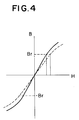
- the excitation energy H required to generate a magnetic field with a flux density of Br in the lumen flow path 6 is smaller than in the prior art, which means a better excitation efficiency.
- the solid line indicates the curve in this embodiment, while the dotted line indicates the curve in the prior art.
- the ground electrodes are formed by the magnetic poles 204, 204, and the y-axis of the magnetic poles 204, 204 serving also as the ground electrodes lies in a plane which contains the x-axis of the signal electrodes 203, 203 and which is at right angles to the axis of the lumen 205, the distance on the axis of the lumen 205 between the signal electrodes 203, 203 and the ground electrodes (in other words, the magnetic poles 204, 204) is never changed by distortion which occurs when the conduit body 202 is formed by a plastic material, for which reason the shifting or variation of zero point which occurs in the prior art can be prevented.
- conduit 201 is produced as a disposable part which is discarded after each surgical procedure, it is unnecessary to inspect the zero point for each conduit in mass-production of the conduits 201, so that the inspection manpower can be saved and the production cost can be reduced accordingly.
- the electromagnetic flowmeter and the conduit according to the present invention are constructed as described, so that costs of material and parts can be decreased and the magnetic efficiency can be improved. Because it is possible to prevent the shifting or variation of the zero point caused by distortion which occurs in forming the conduit, the inspection manpower can be saved.
- the above-mentioned advantages are particularly notable with the parts which need to be produced at low cost, such as disposable conduits.
- the magnetic flux density can be obtained in an improved distribution at the lumen flow path where the electrodes and the magnetic poles are arranged and the flow rate characteristics can enhanced.
- a conduit body is molded.
- holes 313, 313 and 314, 314 into which the electrodes 303, 303 and the magnetic poles 304, 304 are to be inserted are formed. Diameters of holes are little shorter than that of respective poles.
- a layer of anticoagulant is formed on the lumen surface 315 of the conduit body 303. Then, the electrodes 303, 303 and the magnetic poles 304, 304, are press-fitted into the holes 313, 313 and 314, 314, by which the conduit body is formed.
- a metal-resin adhesive such as Araldite (trade name) provided by Chiba-Geigy Corp., may be interposed between walls of the holes and the poles.
Landscapes
- Physics & Mathematics (AREA)
- Electromagnetism (AREA)
- Health & Medical Sciences (AREA)
- General Physics & Mathematics (AREA)
- Fluid Mechanics (AREA)
- Life Sciences & Earth Sciences (AREA)
- Engineering & Computer Science (AREA)
- Biomedical Technology (AREA)
- Surgery (AREA)
- Biophysics (AREA)
- Physiology (AREA)
- Heart & Thoracic Surgery (AREA)
- Medical Informatics (AREA)
- Molecular Biology (AREA)
- Pathology (AREA)
- Animal Behavior & Ethology (AREA)
- General Health & Medical Sciences (AREA)
- Public Health (AREA)
- Veterinary Medicine (AREA)
- Cardiology (AREA)
- Hematology (AREA)
- Power Engineering (AREA)
- Measuring Volume Flow (AREA)
Applications Claiming Priority (2)
| Application Number | Priority Date | Filing Date | Title |
|---|---|---|---|
| JP13619394A JP3410818B2 (ja) | 1994-06-20 | 1994-06-20 | 電磁流量計と流管部 |
| JP136193/94 | 1994-06-20 |
Publications (1)
| Publication Number | Publication Date |
|---|---|
| EP0688531A1 true EP0688531A1 (fr) | 1995-12-27 |
Family
ID=15169522
Family Applications (1)
| Application Number | Title | Priority Date | Filing Date |
|---|---|---|---|
| EP95304314A Withdrawn EP0688531A1 (fr) | 1994-06-20 | 1995-06-20 | Débitmètre électromagnétique |
Country Status (3)
| Country | Link |
|---|---|
| US (1) | US5583299A (fr) |
| EP (1) | EP0688531A1 (fr) |
| JP (1) | JP3410818B2 (fr) |
Cited By (10)
| Publication number | Priority date | Publication date | Assignee | Title |
|---|---|---|---|---|
| WO2003086504A3 (fr) * | 2002-04-10 | 2004-04-15 | Baxter Int | Systemes et procedes de detection de deconnexion d'acces |
| DE102004057695A1 (de) * | 2004-11-30 | 2006-06-01 | Abb Patent Gmbh | Magnetisch induktiver Durchflussmesser mit einem Messrohr aus Kunststoff |
| US8920356B2 (en) | 2002-04-10 | 2014-12-30 | Baxter International Inc. | Conductive polymer materials and applications thereof including monitoring and providing effective therapy |
| US9039648B2 (en) | 2003-11-05 | 2015-05-26 | Baxter International Inc. | Dialysis system with enhanced features |
| WO2015172891A1 (fr) * | 2014-05-15 | 2015-11-19 | Novalung Gmbh | Dispositif de mesure médicotechnique et procédé de mesure |
| US10155082B2 (en) | 2002-04-10 | 2018-12-18 | Baxter International Inc. | Enhanced signal detection for access disconnection systems |
| US10463306B2 (en) | 2014-05-15 | 2019-11-05 | Novalung Gmbh | Medical measuring system and method for production of the measuring system |
| US10814054B2 (en) | 2015-10-23 | 2020-10-27 | Novalung Gmbh | Intermediate element for a medical extracorporeal fluid line, and system and method associated therewith |
| DE102019126013A1 (de) * | 2019-09-26 | 2021-04-01 | Endress+Hauser Flowtec Ag | Magnetisch-induktives Durchflussmessgerät |
| DE102023134021A1 (de) * | 2023-12-05 | 2025-06-05 | Endress+Hauser Wetzer Gmbh+Co. Kg | Klemmeinheit und Messaufnehmer mit Klemmeinheit |
Families Citing this family (21)
| Publication number | Priority date | Publication date | Assignee | Title |
|---|---|---|---|---|
| EP0762084A3 (fr) * | 1995-09-12 | 1998-04-22 | Georg Fischer Rohrleitungssysteme AG | Débimètre électromagnétique |
| DE19535997C2 (de) | 1995-09-27 | 1997-09-25 | Ketelsen Broder | Induktiver Durchflußmesser |
| US5767418A (en) * | 1997-01-21 | 1998-06-16 | Elsag International N.V. | Electromagnetic flowmeter with single bobbin coil |
| US5847287A (en) * | 1997-01-21 | 1998-12-08 | Elsag International N.V. | Electromagnetic flowmeter with self-sealing electrodes |
| EP1125098B1 (fr) | 1998-09-29 | 2016-07-27 | Scientific Generics Limited | Compteur electromagnetique |
| JP2006010597A (ja) * | 2004-06-29 | 2006-01-12 | Takashi Wada | 液体切れ検知センサ |
| DE102005002907A1 (de) * | 2005-01-21 | 2006-07-27 | Abb Patent Gmbh | Magnetisch-induktives Durchflussmessgerät |
| US7055396B1 (en) * | 2005-03-28 | 2006-06-06 | George Fischer Signet, Inc. | Sensor assembly for magnetic flowmeter and method of manufacture |
| JP4718892B2 (ja) * | 2005-05-11 | 2011-07-06 | 愛知時計電機株式会社 | 流量計測用医療管、流量計測用医療容器及び排液流量計測装置 |
| JP2006343254A (ja) * | 2005-06-10 | 2006-12-21 | Aichi Tokei Denki Co Ltd | 腹膜透析用電磁流量計及び腹膜透析装置 |
| GB2440964B (en) * | 2006-08-18 | 2011-08-10 | Abb Ltd | Flow meter |
| GB2440963B (en) * | 2006-08-18 | 2011-06-08 | Abb Ltd | Flow meter |
| DE102007061798A1 (de) | 2007-12-19 | 2009-06-25 | Endress + Hauser Flowtec Ag | Magnetisch induktives Durchflussmesssystem zur Bestimmung und/oder Überwachung eines Durchflusses eines Messmediums durch ein Messrohr |
| DE102008035740A1 (de) * | 2008-07-31 | 2010-02-04 | Abb Technology Ag | Magnetisch induktiver Durchflussmesser mit einer kombinierte magnetische Flussleitmittel umfassenden Elektromagenteinheit |
| DE102010031433A1 (de) | 2010-07-16 | 2012-01-19 | Endress + Hauser Flowtec Ag | Einsatz für ein magnetisch-induktives Durchflussmessgerät |
| US9631961B2 (en) * | 2015-08-19 | 2017-04-25 | Sensus Spectrum Llc | Inductive flow meter including extended magnetic pole pieces |
| EP3732447B1 (fr) * | 2017-12-29 | 2025-03-19 | ABB Schweiz AG | Débitmètre électromagnétique de type serre-tube |
| US11365995B2 (en) * | 2018-09-28 | 2022-06-21 | Georg Fischer Signet Llc | Magnetic flowmeter including auxiliary electrodes upstream and downstream of the pair of measuring electrodes and an adjustable brace |
| EP3893960B1 (fr) * | 2018-12-14 | 2023-02-22 | MAQUET Cardiopulmonary GmbH | Appareil de détection d'écoulement de fluide et de détection de bulles |
| DE102019135011A1 (de) * | 2019-12-18 | 2021-06-24 | Endress+Hauser Flowtec Ag | Messrohr, Aufnahmeeinheit und magnetisch-induktives Durchflussmessgerät |
| DE102019135017B3 (de) | 2019-12-18 | 2021-08-12 | Endress+Hauser Flowtec Ag | Messrohr, Aufnahmeeinheit und magnetisch-induktives Durchflussmessgerät |
Citations (7)
| Publication number | Priority date | Publication date | Assignee | Title |
|---|---|---|---|---|
| US2149847A (en) | 1937-07-15 | 1939-03-07 | Kolin Alexander | Apparatus for measuring fluid flow |
| US4118981A (en) | 1977-06-24 | 1978-10-10 | Arcadia Refining Company | Flowmeter |
| US4195515A (en) | 1976-06-28 | 1980-04-01 | Smoll Owen C | In line electromagnetic flow measurement transducer |
| GB2160658A (en) * | 1984-06-06 | 1985-12-24 | Danfoss As | Electromagnetic flow meter |
| US4881413A (en) | 1988-10-31 | 1989-11-21 | Bio-Medicus, Inc. | Blood flow detection device |
| EP0459480A1 (fr) * | 1990-05-31 | 1991-12-04 | Nihon Kohden Corporation | Sonde de débimètre électromagnétique de sang |
| JPH04324320A (ja) | 1991-04-25 | 1992-11-13 | Aichi Tokei Denki Co Ltd | 電磁流量計 |
Family Cites Families (6)
| Publication number | Priority date | Publication date | Assignee | Title |
|---|---|---|---|---|
| US2766621A (en) * | 1952-04-21 | 1956-10-16 | Vitro Corp Of America | Grounding means for a flowmeter |
| US3309924A (en) * | 1964-06-22 | 1967-03-21 | Universtity Of California | Electromagnetic flow meter |
| EP0047342B1 (fr) * | 1980-09-04 | 1984-01-11 | Rheometron Ag | Tête de mesure pour débitmètres électromagnétiques |
| JP2540649B2 (ja) * | 1990-04-27 | 1996-10-09 | テルモ株式会社 | 採血管 |
| JP2947634B2 (ja) * | 1991-04-25 | 1999-09-13 | 愛知時計電機株式会社 | 電磁流量計 |
| US5325728A (en) * | 1993-06-22 | 1994-07-05 | Medtronic, Inc. | Electromagnetic flow meter |
-
1994
- 1994-06-20 JP JP13619394A patent/JP3410818B2/ja not_active Expired - Fee Related
-
1995
- 1995-06-19 US US08/492,150 patent/US5583299A/en not_active Expired - Fee Related
- 1995-06-20 EP EP95304314A patent/EP0688531A1/fr not_active Withdrawn
Patent Citations (7)
| Publication number | Priority date | Publication date | Assignee | Title |
|---|---|---|---|---|
| US2149847A (en) | 1937-07-15 | 1939-03-07 | Kolin Alexander | Apparatus for measuring fluid flow |
| US4195515A (en) | 1976-06-28 | 1980-04-01 | Smoll Owen C | In line electromagnetic flow measurement transducer |
| US4118981A (en) | 1977-06-24 | 1978-10-10 | Arcadia Refining Company | Flowmeter |
| GB2160658A (en) * | 1984-06-06 | 1985-12-24 | Danfoss As | Electromagnetic flow meter |
| US4881413A (en) | 1988-10-31 | 1989-11-21 | Bio-Medicus, Inc. | Blood flow detection device |
| EP0459480A1 (fr) * | 1990-05-31 | 1991-12-04 | Nihon Kohden Corporation | Sonde de débimètre électromagnétique de sang |
| JPH04324320A (ja) | 1991-04-25 | 1992-11-13 | Aichi Tokei Denki Co Ltd | 電磁流量計 |
Cited By (17)
| Publication number | Priority date | Publication date | Assignee | Title |
|---|---|---|---|---|
| US10155082B2 (en) | 2002-04-10 | 2018-12-18 | Baxter International Inc. | Enhanced signal detection for access disconnection systems |
| US7052480B2 (en) | 2002-04-10 | 2006-05-30 | Baxter International Inc. | Access disconnection systems and methods |
| US8920356B2 (en) | 2002-04-10 | 2014-12-30 | Baxter International Inc. | Conductive polymer materials and applications thereof including monitoring and providing effective therapy |
| WO2003086504A3 (fr) * | 2002-04-10 | 2004-04-15 | Baxter Int | Systemes et procedes de detection de deconnexion d'acces |
| US9039648B2 (en) | 2003-11-05 | 2015-05-26 | Baxter International Inc. | Dialysis system with enhanced features |
| US9550020B2 (en) | 2003-11-05 | 2017-01-24 | Baxter International Inc. | Dialysis system with a varying rate ultrafiltration profile |
| DE102004057695A1 (de) * | 2004-11-30 | 2006-06-01 | Abb Patent Gmbh | Magnetisch induktiver Durchflussmesser mit einem Messrohr aus Kunststoff |
| DE102004057695B4 (de) * | 2004-11-30 | 2009-12-24 | Abb Ag | Magnetisch induktiver Durchflussmesser mit einem Messrohr aus Kunststoff |
| US10391227B2 (en) | 2014-05-15 | 2019-08-27 | Novalung Gmbh | Medico-technical measuring device and measuring method |
| US10463306B2 (en) | 2014-05-15 | 2019-11-05 | Novalung Gmbh | Medical measuring system and method for production of the measuring system |
| WO2015172891A1 (fr) * | 2014-05-15 | 2015-11-19 | Novalung Gmbh | Dispositif de mesure médicotechnique et procédé de mesure |
| EP3590564A1 (fr) * | 2014-05-15 | 2020-01-08 | novalung GmbH | Dispositif de mesure médical et procédé de mesure |
| US11357899B2 (en) | 2014-05-15 | 2022-06-14 | Novalung Gmbh | Measuring device and method for measuring a property of a fluid in a line |
| US10814054B2 (en) | 2015-10-23 | 2020-10-27 | Novalung Gmbh | Intermediate element for a medical extracorporeal fluid line, and system and method associated therewith |
| DE102019126013A1 (de) * | 2019-09-26 | 2021-04-01 | Endress+Hauser Flowtec Ag | Magnetisch-induktives Durchflussmessgerät |
| US12117322B2 (en) | 2019-09-26 | 2024-10-15 | Endress+Hauser Flowtec Ag | Magnetic-inductive flowmeter |
| DE102023134021A1 (de) * | 2023-12-05 | 2025-06-05 | Endress+Hauser Wetzer Gmbh+Co. Kg | Klemmeinheit und Messaufnehmer mit Klemmeinheit |
Also Published As
| Publication number | Publication date |
|---|---|
| JP3410818B2 (ja) | 2003-05-26 |
| US5583299A (en) | 1996-12-10 |
| JPH085423A (ja) | 1996-01-12 |
Similar Documents
| Publication | Publication Date | Title |
|---|---|---|
| US5583299A (en) | Conduit for an electromagnetic flowmeter using magnetic poles as ground electrodes | |
| US4175566A (en) | Catheter fluid-velocity flow probe | |
| US6559636B1 (en) | Modular waveguide assembly and method for making the same | |
| US7659709B2 (en) | Electric current sensor having housing with rails to insert support board | |
| US6260420B1 (en) | Inductive flow meter signal line and electrode arrangement | |
| KR100564978B1 (ko) | 용량식 전자 유량계 | |
| US5450758A (en) | Bioprobe replacement sensor and transducer | |
| CN101688887B (zh) | 罗格夫斯基电流传感器 | |
| EP2095840A1 (fr) | Appareil d'interconnexion de fil-guide | |
| WO2018198419A1 (fr) | Débitmètre électromagnétique | |
| US20060185442A1 (en) | Magnetoinductive flowmeter | |
| WO2018073121A1 (fr) | Transducteur de courant électrique | |
| CN102112884A (zh) | 非接触式环形探头 | |
| US3446071A (en) | Split-pole electromagnetic flow transducer | |
| US3504541A (en) | Detector heads | |
| US20220397435A1 (en) | Magnetically-inductive flow meter | |
| JPH0728166B2 (ja) | フィルタ及びその製造方法 | |
| DE102006020265A1 (de) | Magnetisch-induktiver Meßaufnehmer | |
| EP0459480A1 (fr) | Sonde de débimètre électromagnétique de sang | |
| US5121640A (en) | Electromagnetic flow meter | |
| CN118511058A (zh) | 磁感应流量计 | |
| JPH02121286A (ja) | 耐放射線性気密型電気コネクター | |
| JP3641919B2 (ja) | 電磁流量計の検出部構造 | |
| JPH02218902A (ja) | 渦電流式変位センサ | |
| JP2547247B2 (ja) | 金属線間距離測定センサ |
Legal Events
| Date | Code | Title | Description |
|---|---|---|---|
| PUAI | Public reference made under article 153(3) epc to a published international application that has entered the european phase |
Free format text: ORIGINAL CODE: 0009012 |
|
| AK | Designated contracting states |
Kind code of ref document: A1 Designated state(s): CH DE FR GB LI |
|
| 17P | Request for examination filed |
Effective date: 19960513 |
|
| 17Q | First examination report despatched |
Effective date: 19990525 |
|
| STAA | Information on the status of an ep patent application or granted ep patent |
Free format text: STATUS: THE APPLICATION IS DEEMED TO BE WITHDRAWN |
|
| 18D | Application deemed to be withdrawn |
Effective date: 20010103 |