EP0688659A2 - Outil de poinçonnage et de formage pour la fabrication de récipients en matière thermoplastique - Google Patents
Outil de poinçonnage et de formage pour la fabrication de récipients en matière thermoplastique Download PDFInfo
- Publication number
- EP0688659A2 EP0688659A2 EP95108966A EP95108966A EP0688659A2 EP 0688659 A2 EP0688659 A2 EP 0688659A2 EP 95108966 A EP95108966 A EP 95108966A EP 95108966 A EP95108966 A EP 95108966A EP 0688659 A2 EP0688659 A2 EP 0688659A2
- Authority
- EP
- European Patent Office
- Prior art keywords
- hold
- piston
- tool according
- punching tool
- down device
- Prior art date
- Legal status (The legal status is an assumption and is not a legal conclusion. Google has not performed a legal analysis and makes no representation as to the accuracy of the status listed.)
- Withdrawn
Links
Images


Classifications
-
- B—PERFORMING OPERATIONS; TRANSPORTING
- B29—WORKING OF PLASTICS; WORKING OF SUBSTANCES IN A PLASTIC STATE IN GENERAL
- B29C—SHAPING OR JOINING OF PLASTICS; SHAPING OF MATERIAL IN A PLASTIC STATE, NOT OTHERWISE PROVIDED FOR; AFTER-TREATMENT OF THE SHAPED PRODUCTS, e.g. REPAIRING
- B29C51/00—Shaping by thermoforming, i.e. shaping sheets or sheet like preforms after heating, e.g. shaping sheets in matched moulds or by deep-drawing; Apparatus therefor
- B29C51/26—Component parts, details or accessories; Auxiliary operations
- B29C51/261—Handling means, e.g. transfer means, feeding means
- B29C51/262—Clamping means for the sheets, e.g. clamping frames
Definitions
- the invention relates to a form-punching tool for producing containers from thermoplastic plastic film according to the preamble of the main claim.
- the hold-down device which is designed as an annular piston, is pressurized with compressed air, so that the force of the hold-down device can be controlled as a function of the process sequence. This means that when the tool is closed to protect the drive, no hold-down force can be applied and this hold-down force can only be built up when the tool is closed or when the punched-out container is pushed out when the tool is opened.
- the shaped air for molding the container is supplied from the same tank as the compressed air for generating the hold-down force.
- the shaped air counteracts the hold-down force inside the closed mold and, depending on the dimensional conditions, more or less abolishes it or it even becomes greater than the hold-down force. This is irrelevant if the hold-down force is only used to eject the molded container, because the molding air is already vented when it is ejected.
- the invention had for its object to design the tool so that a sufficient hold-down force can be achieved when using compressed air with a pressure that corresponds essentially to the pressure of the molding air.
- Special high pressure generators and networks should not be required.
- the design measures should ensure a safe and reliable mode of operation and should be within the budget.
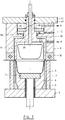
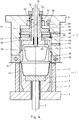
- FIGS. 1-4 each show a cross section through a mold cavity of a form-punching tool in four different embodiments.
- the form-punching tool in all 4 embodiments shown consists of two mold halves, the lower part 1 and the upper part 2.
- the lower part 1 is composed of a base plate 3, the cooling block 4, inserted punches 5, mold inserts 6 and bottoms 7 each an ejector rod 8 together.
- the arrangement of the individual mold cavities in the cooling block 4 can be single-row or multi-row. Each row can have several mold cavities.
- the upper part 2 has a cutting plate 10 mounted on the intermediate plate 9 and a head plate 11.
- the intermediate plate 9 and head plate 11 can, as shown in Figure 4, consist of one piece. Openings 12 are provided in the cutting plate 10 in accordance with the contour of the container 13 to be punched out.
- In each breakthrough 12 there is a pot-shaped hold-down device 14 which merges into a shaft 15 with several shoulders.
- holes 21 with a larger diameter than the openings 12 are arranged in the intermediate plate 9.
- a pot 22 is inserted into each bore 21 and held by a collar 23.
- the bottom of the pot 23 is designed as a collar 24 and has a bore 25 corresponding to the diameter of the shoulder 16.
- a seal 26 is provided at this point of contact.
- On the shoulder 16 of the shaft 15 sits a piston 27 which extends outwards to the bore 21 and carries a circumferential seal 28.
- the shoulder 17 of the shaft 15 protrudes through the head plate 11 and is fastened outside with a nut 29 which sits on the thread of the shoulder 18.
- a compression spring 30 is mounted between the head plate 11 and the piston 27 to support the hold-down force and to define the position of the hold-down device 14. Formed air can be conducted into the interior of the hold-down device 14 via bores 31, 32.
- Compressed air is guided to the top of the piston 27 via the bore 33.
- the resulting force is transmitted via the shoulder of the shoulder 16 to the hold-down device 14 and thus to its ring surface 35 facing the film web 34. This force is used to calibrate / crush / shape the clamped container edge.
- FIG. 2 A second embodiment of the form-punching tool is shown in FIG. 2.
- the intermediate plate 9 is provided on both sides with a bore 36, 37, the depth of which is coordinated so that a collar 38 remains, in the bore 39 of which the shoulder 16 of the hold-down device 14 is guided.
- a piston 42 slides in the bore 37, which is supported on the collar of the shoulder 16 and is prestressed by a compression spring 40.
- the hold-down force is generated by supplying compressed air through the bore 41 into the space between the piston 42 and the top plate 11.
- Figure 3 shows a modification of the form-punching tool according to Figure 2 in such a way that a collar 43 for guiding the shoulder 16 is formed in such a way that a pot 45 is inserted into a bore 44 in the intermediate plate 9, the bottom of which this fret 43 forms.
- This design has the advantage that the bores 36 and 44 can be machined from one side, that is, without the intermediate plate 9 having to be reclamped, so that there is no risk of eccentricity.
- FIGS. 1 to 3 have the disadvantage that not all parts of the hold-down device, including the high-pressure device, can be installed or removed from the parting plane when the tool is open.
- the embodiment according to FIG. 4 avoids this disadvantage, so that maintenance and repair work are possible without having to dismantle the other parts of the tool.
- holes 46 with a smaller diameter than the openings 12 in the cutting plate 10 are provided in the intermediate plate 9.
- each bore 46 there is an annular piston 47, held on the one hand by a shoulder 48, on the other hand by a retaining ring 49 (FIG. 4 on the right) or held between two retaining rings 49 (FIG. 4 on the left).
- the solution with a shoulder 48 is followed by a slightly smaller diameter bore 50 in which a piston 51 is seated, which in the direction of the end of the shaft 15 merges into a shoulder 52 which extends as far as the stop nut 53 which sits on the shaft 15 .
- the piston 24 has an extension 63 which extends through the collar 24 to the shoulder 55 of the hold-down device 14.
- the piston 51 is acted upon by a compression spring 57, which thus presses the entire hold-down device 4 down until the stop nut 53 bears against the upper edge of the intermediate plate 9.
- Compressed air can be directed to the top of the piston 51 via bores 58, 59.
- a bore 61 is provided in the intermediate plate 9 for the supply of shaped air. Via a further bore 62, this reaches the inside of the hold-down device 14.
- a bore 60 serves to vent the space between the piston 51 and the annular piston 47.
- the tool is installed in the forming station of a thermoforming machine and works as follows: When the tool is open, a section of a heated film web 34 is transported between the two tool halves 1, 2 and this is closed to such an extent that the film web 34 is partially severed by the cutting punches 5.
- the hold-down devices 14 move back accordingly. For this purpose, only the force of the springs 25, 40, 57 must be overcome by the drive of the thermoforming machine. In this closed position, the compressed air is supplied through corresponding holes on the top of the piston 27, 42, 51, whereby the hold-down device 14 is pressed down. This forms the edge of the container.
- the supply of the shaped air and, if appropriate, the stretching aid insert takes place in a known manner, as a result of which the containers 13 are deformed.
- the compressed air for the hold-down force first escapes, so that the hold-down force is reduced when the lower die part 1 starts to punch. Then the mold air escapes, the tool opens and the shaped articles are transported out and stacked in a known manner.
Landscapes
- Engineering & Computer Science (AREA)
- Mechanical Engineering (AREA)
- Blow-Moulding Or Thermoforming Of Plastics Or The Like (AREA)
Applications Claiming Priority (4)
| Application Number | Priority Date | Filing Date | Title |
|---|---|---|---|
| DE4421979 | 1994-06-23 | ||
| DE4421979A DE4421979C1 (de) | 1994-06-23 | 1994-06-23 | Form- Stanz-Werkzeug zum Herstellen von Behältern aus thermoplastischer Kunststoffolie |
| DE19944445376 DE4445376C1 (de) | 1994-12-20 | 1994-12-20 | Form-Stanz-Werkzeug zum Herstellen von Behältern aus thermoplastischer Kunststoffolie |
| DE4445376 | 1994-12-20 |
Publications (2)
| Publication Number | Publication Date |
|---|---|
| EP0688659A2 true EP0688659A2 (fr) | 1995-12-27 |
| EP0688659A3 EP0688659A3 (fr) | 1997-10-08 |
Family
ID=25937664
Family Applications (1)
| Application Number | Title | Priority Date | Filing Date |
|---|---|---|---|
| EP95108966A Withdrawn EP0688659A3 (fr) | 1994-06-23 | 1995-06-10 | Outil de poinçonnage et de formage pour la fabrication de récipients en matière thermoplastique |
Country Status (1)
| Country | Link |
|---|---|
| EP (1) | EP0688659A3 (fr) |
Cited By (3)
| Publication number | Priority date | Publication date | Assignee | Title |
|---|---|---|---|---|
| DE19958065A1 (de) * | 1999-12-02 | 2001-06-28 | Optipack Gmbh & Co Kg | Vorrichtung zum Tiefziehen von becherförmigen Körpern |
| EP1377919A2 (fr) * | 2000-07-24 | 2004-01-07 | PACT XPP Technologies AG | Circuit integre |
| DE202011001622U1 (de) * | 2011-01-17 | 2012-04-18 | Gizeh Verpackungen Gmbh & Co. Kg | Druckgas-Thermoform-Vorrichtung |
Citations (1)
| Publication number | Priority date | Publication date | Assignee | Title |
|---|---|---|---|---|
| EP0525483A1 (fr) | 1991-07-27 | 1993-02-03 | Verpaco Ag | Appareil pour la production de récipients en plastique |
Family Cites Families (3)
| Publication number | Priority date | Publication date | Assignee | Title |
|---|---|---|---|---|
| DE2145250A1 (de) * | 1971-09-10 | 1973-03-15 | Wilhelm Anton Haeberle | Vorrichtung zur herstellung von behaeltern aus thermoplastisch verformbaren kunststoff-folien |
| DE3936891A1 (de) * | 1989-11-06 | 1991-05-08 | Illig Maschinenbau Adolf | Formwerkzeug zum herstellen von bechern aus einer erwaermten thermoplastischen kunststoffolie |
| DE4326190A1 (de) * | 1993-08-04 | 1995-02-09 | Marbach Werkzeugbau Gmbh | Thermoformwerkzeug |
-
1995
- 1995-06-10 EP EP95108966A patent/EP0688659A3/fr not_active Withdrawn
Patent Citations (1)
| Publication number | Priority date | Publication date | Assignee | Title |
|---|---|---|---|---|
| EP0525483A1 (fr) | 1991-07-27 | 1993-02-03 | Verpaco Ag | Appareil pour la production de récipients en plastique |
Cited By (4)
| Publication number | Priority date | Publication date | Assignee | Title |
|---|---|---|---|---|
| DE19958065A1 (de) * | 1999-12-02 | 2001-06-28 | Optipack Gmbh & Co Kg | Vorrichtung zum Tiefziehen von becherförmigen Körpern |
| DE19958065C2 (de) * | 1999-12-02 | 2001-12-06 | Optipack Gmbh & Co Kg | Vorrichtung zum Tiefziehen von becherförmigen Körpern |
| EP1377919A2 (fr) * | 2000-07-24 | 2004-01-07 | PACT XPP Technologies AG | Circuit integre |
| DE202011001622U1 (de) * | 2011-01-17 | 2012-04-18 | Gizeh Verpackungen Gmbh & Co. Kg | Druckgas-Thermoform-Vorrichtung |
Also Published As
| Publication number | Publication date |
|---|---|
| EP0688659A3 (fr) | 1997-10-08 |
Similar Documents
| Publication | Publication Date | Title |
|---|---|---|
| DE4322063C2 (de) | Verfahren und Vorrichtung zum Ausschneiden eines Ausschnittes aus einer Wandung eines nach dem Innenhochdruck-Umformverfahren hergestellten Hohlkörpers | |
| DE10030010C2 (de) | Verfahren zum Herstellen eines Behälters aus einer thermoplastischen Kunststofffolie und Formwerkzeug zur Durchführung des Verfahrens | |
| DE3931320C1 (fr) | ||
| EP1497099A1 (fr) | Installation de thermoformage pour la production de corps fa onnes a partir d'un film de plastique, et procede de production de tels corps | |
| DE19506067C1 (de) | Verfahren zum Ausschneiden eines Ausschnitts aus der Wandung eines als Hohlkörper ausgebildeten Bauteils und Vorrichtung zur Durchführung des Verfahrens | |
| DE19842750A1 (de) | Verfahren und Herstellung von tiefgezogenen Hohlteilen und Ziehwerkzeug | |
| DE2752594A1 (de) | Vorrichtung zum ausstanzen und tiefziehen von werkstuecken aus blech o.dgl. | |
| EP2999582B1 (fr) | Outil, station d'outils, installation de thermoformage et procédé pour faire fonctionner une installation de thermoformage | |
| EP0845312B1 (fr) | Outil pour formage à haute pression utilisable avec flexibilité | |
| EP0688659A2 (fr) | Outil de poinçonnage et de formage pour la fabrication de récipients en matière thermoplastique | |
| DE4421979C1 (de) | Form- Stanz-Werkzeug zum Herstellen von Behältern aus thermoplastischer Kunststoffolie | |
| DE19805275A1 (de) | Verfahren und Vorrichtung zum Einbringen eines Durchbruches in eine Wand | |
| DE19948768C1 (de) | Vorrichtung zum Formen und Ausstanzen von Behältern aus einer thermoplastischen Kunststoffolie | |
| DE102007011292B4 (de) | Formwerkzeug zum Aufbringen eines Etiketts auf ein tiefgezogenes Formteil und Verfahren zum Betreiben des Formwerkzeugs | |
| DE4445376C1 (de) | Form-Stanz-Werkzeug zum Herstellen von Behältern aus thermoplastischer Kunststoffolie | |
| DE102004012439B4 (de) | Verfahren zum Tiefziehen und Ausstanzen von Behältern aus einer thermoplastischen Kunststofffolie und Vorrichtung zum Tiefziehen und Ausstanzen von Behältern | |
| EP1344628B1 (fr) | Appareil pour l'emboutissage de récipients en thermoplastique | |
| DE19532571C1 (de) | Formwerkzeug zum Herstellen von Behältern aus einer thermoplastischen Kunststoffolie | |
| DE19911125C1 (de) | Verfahren und Vorrichtung zum Trennen oder Lochen eines Werkstücks unter Einfluß eines unter Hochdruck stehenden Druckmediums | |
| EP2052843B1 (fr) | Procédé de fonctionnement d'un dispositif destiné à la fabrication de pièces de formage à partir d'une feuille de matière synthétique thermoplastique | |
| DE9109287U1 (de) | Formwerkzeug zur Herstellung von Kunststoffbechern | |
| DE9421923U1 (de) | Form-Stanzwerkzeug zum Herstellen von Behältern aus thermoplastischer Kunststoffolie | |
| DE102004012858B4 (de) | Verfahren und Einrichtung zur Wälzkörperherstellung | |
| EP0561310A1 (fr) | Dispositif pour la déformation à froid de feuilles en plastique, en particulier feuilles de différentes épaisseurs en polypropylène | |
| DE2931715C2 (de) | Formwerkzeug zur Herstellung von Membranen |
Legal Events
| Date | Code | Title | Description |
|---|---|---|---|
| PUAI | Public reference made under article 153(3) epc to a published international application that has entered the european phase |
Free format text: ORIGINAL CODE: 0009012 |
|
| AK | Designated contracting states |
Kind code of ref document: A2 Designated state(s): CH DE FR GB IT LI NL |
|
| PUAL | Search report despatched |
Free format text: ORIGINAL CODE: 0009013 |
|
| AK | Designated contracting states |
Kind code of ref document: A3 Designated state(s): CH DE FR GB IT LI NL |
|
| 17P | Request for examination filed |
Effective date: 19970829 |
|
| 17Q | First examination report despatched |
Effective date: 19990427 |
|
| STAA | Information on the status of an ep patent application or granted ep patent |
Free format text: STATUS: THE APPLICATION HAS BEEN WITHDRAWN |
|
| 18W | Application withdrawn |
Withdrawal date: 19990814 |