EP0688943A1 - Système d'admission d'air d'un moteur à combustion multicylindrique - Google Patents
Système d'admission d'air d'un moteur à combustion multicylindrique Download PDFInfo
- Publication number
- EP0688943A1 EP0688943A1 EP95106485A EP95106485A EP0688943A1 EP 0688943 A1 EP0688943 A1 EP 0688943A1 EP 95106485 A EP95106485 A EP 95106485A EP 95106485 A EP95106485 A EP 95106485A EP 0688943 A1 EP0688943 A1 EP 0688943A1
- Authority
- EP
- European Patent Office
- Prior art keywords
- air intake
- intake system
- connecting tube
- bearing
- bearing bridge
- Prior art date
- Legal status (The legal status is an assumption and is not a legal conclusion. Google has not performed a legal analysis and makes no representation as to the accuracy of the status listed.)
- Granted
Links
Images


Classifications
-
- F—MECHANICAL ENGINEERING; LIGHTING; HEATING; WEAPONS; BLASTING
- F02—COMBUSTION ENGINES; HOT-GAS OR COMBUSTION-PRODUCT ENGINE PLANTS
- F02D—CONTROLLING COMBUSTION ENGINES
- F02D9/00—Controlling engines by throttling air or fuel-and-air induction conduits or exhaust conduits
- F02D9/08—Throttle valves specially adapted therefor; Arrangements of such valves in conduits
- F02D9/10—Throttle valves specially adapted therefor; Arrangements of such valves in conduits having pivotally-mounted flaps
-
- F—MECHANICAL ENGINEERING; LIGHTING; HEATING; WEAPONS; BLASTING
- F02—COMBUSTION ENGINES; HOT-GAS OR COMBUSTION-PRODUCT ENGINE PLANTS
- F02B—INTERNAL-COMBUSTION PISTON ENGINES; COMBUSTION ENGINES IN GENERAL
- F02B27/00—Use of kinetic or wave energy of charge in induction systems, or of combustion residues in exhaust systems, for improving quantity of charge or for increasing removal of combustion residues
- F02B27/02—Use of kinetic or wave energy of charge in induction systems, or of combustion residues in exhaust systems, for improving quantity of charge or for increasing removal of combustion residues the systems having variable, i.e. adjustable, cross-sectional areas, chambers of variable volume, or like variable means
-
- F—MECHANICAL ENGINEERING; LIGHTING; HEATING; WEAPONS; BLASTING
- F02—COMBUSTION ENGINES; HOT-GAS OR COMBUSTION-PRODUCT ENGINE PLANTS
- F02B—INTERNAL-COMBUSTION PISTON ENGINES; COMBUSTION ENGINES IN GENERAL
- F02B27/00—Use of kinetic or wave energy of charge in induction systems, or of combustion residues in exhaust systems, for improving quantity of charge or for increasing removal of combustion residues
- F02B27/02—Use of kinetic or wave energy of charge in induction systems, or of combustion residues in exhaust systems, for improving quantity of charge or for increasing removal of combustion residues the systems having variable, i.e. adjustable, cross-sectional areas, chambers of variable volume, or like variable means
- F02B27/0205—Use of kinetic or wave energy of charge in induction systems, or of combustion residues in exhaust systems, for improving quantity of charge or for increasing removal of combustion residues the systems having variable, i.e. adjustable, cross-sectional areas, chambers of variable volume, or like variable means characterised by the charging effect
- F02B27/0215—Oscillating pipe charging, i.e. variable intake pipe length charging
- F02B27/0221—Resonance charging combined with oscillating pipe charging
-
- F—MECHANICAL ENGINEERING; LIGHTING; HEATING; WEAPONS; BLASTING
- F02—COMBUSTION ENGINES; HOT-GAS OR COMBUSTION-PRODUCT ENGINE PLANTS
- F02B—INTERNAL-COMBUSTION PISTON ENGINES; COMBUSTION ENGINES IN GENERAL
- F02B27/00—Use of kinetic or wave energy of charge in induction systems, or of combustion residues in exhaust systems, for improving quantity of charge or for increasing removal of combustion residues
- F02B27/02—Use of kinetic or wave energy of charge in induction systems, or of combustion residues in exhaust systems, for improving quantity of charge or for increasing removal of combustion residues the systems having variable, i.e. adjustable, cross-sectional areas, chambers of variable volume, or like variable means
- F02B27/0226—Use of kinetic or wave energy of charge in induction systems, or of combustion residues in exhaust systems, for improving quantity of charge or for increasing removal of combustion residues the systems having variable, i.e. adjustable, cross-sectional areas, chambers of variable volume, or like variable means characterised by the means generating the charging effect
- F02B27/0231—Movable ducts, walls or the like
-
- F—MECHANICAL ENGINEERING; LIGHTING; HEATING; WEAPONS; BLASTING
- F02—COMBUSTION ENGINES; HOT-GAS OR COMBUSTION-PRODUCT ENGINE PLANTS
- F02B—INTERNAL-COMBUSTION PISTON ENGINES; COMBUSTION ENGINES IN GENERAL
- F02B27/00—Use of kinetic or wave energy of charge in induction systems, or of combustion residues in exhaust systems, for improving quantity of charge or for increasing removal of combustion residues
- F02B27/02—Use of kinetic or wave energy of charge in induction systems, or of combustion residues in exhaust systems, for improving quantity of charge or for increasing removal of combustion residues the systems having variable, i.e. adjustable, cross-sectional areas, chambers of variable volume, or like variable means
- F02B27/0226—Use of kinetic or wave energy of charge in induction systems, or of combustion residues in exhaust systems, for improving quantity of charge or for increasing removal of combustion residues the systems having variable, i.e. adjustable, cross-sectional areas, chambers of variable volume, or like variable means characterised by the means generating the charging effect
- F02B27/0242—Fluid communication passages between intake ducts, runners or chambers
-
- F—MECHANICAL ENGINEERING; LIGHTING; HEATING; WEAPONS; BLASTING
- F02—COMBUSTION ENGINES; HOT-GAS OR COMBUSTION-PRODUCT ENGINE PLANTS
- F02B—INTERNAL-COMBUSTION PISTON ENGINES; COMBUSTION ENGINES IN GENERAL
- F02B27/00—Use of kinetic or wave energy of charge in induction systems, or of combustion residues in exhaust systems, for improving quantity of charge or for increasing removal of combustion residues
- F02B27/02—Use of kinetic or wave energy of charge in induction systems, or of combustion residues in exhaust systems, for improving quantity of charge or for increasing removal of combustion residues the systems having variable, i.e. adjustable, cross-sectional areas, chambers of variable volume, or like variable means
- F02B27/0226—Use of kinetic or wave energy of charge in induction systems, or of combustion residues in exhaust systems, for improving quantity of charge or for increasing removal of combustion residues the systems having variable, i.e. adjustable, cross-sectional areas, chambers of variable volume, or like variable means characterised by the means generating the charging effect
- F02B27/0247—Plenum chambers; Resonance chambers or resonance pipes
- F02B27/0252—Multiple plenum chambers or plenum chambers having inner separation walls, e.g. comprising valves for the same group of cylinders
-
- F—MECHANICAL ENGINEERING; LIGHTING; HEATING; WEAPONS; BLASTING
- F02—COMBUSTION ENGINES; HOT-GAS OR COMBUSTION-PRODUCT ENGINE PLANTS
- F02B—INTERNAL-COMBUSTION PISTON ENGINES; COMBUSTION ENGINES IN GENERAL
- F02B27/00—Use of kinetic or wave energy of charge in induction systems, or of combustion residues in exhaust systems, for improving quantity of charge or for increasing removal of combustion residues
- F02B27/02—Use of kinetic or wave energy of charge in induction systems, or of combustion residues in exhaust systems, for improving quantity of charge or for increasing removal of combustion residues the systems having variable, i.e. adjustable, cross-sectional areas, chambers of variable volume, or like variable means
- F02B27/0226—Use of kinetic or wave energy of charge in induction systems, or of combustion residues in exhaust systems, for improving quantity of charge or for increasing removal of combustion residues the systems having variable, i.e. adjustable, cross-sectional areas, chambers of variable volume, or like variable means characterised by the means generating the charging effect
- F02B27/0268—Valves
- F02B27/0273—Flap valves
-
- F—MECHANICAL ENGINEERING; LIGHTING; HEATING; WEAPONS; BLASTING
- F16—ENGINEERING ELEMENTS AND UNITS; GENERAL MEASURES FOR PRODUCING AND MAINTAINING EFFECTIVE FUNCTIONING OF MACHINES OR INSTALLATIONS; THERMAL INSULATION IN GENERAL
- F16K—VALVES; TAPS; COCKS; ACTUATING-FLOATS; DEVICES FOR VENTING OR AERATING
- F16K1/00—Lift valves or globe valves, i.e. cut-off apparatus with closure members having at least a component of their opening and closing motion perpendicular to the closing faces
- F16K1/16—Lift valves or globe valves, i.e. cut-off apparatus with closure members having at least a component of their opening and closing motion perpendicular to the closing faces with pivoted closure-members
- F16K1/18—Lift valves or globe valves, i.e. cut-off apparatus with closure members having at least a component of their opening and closing motion perpendicular to the closing faces with pivoted closure-members with pivoted discs or flaps
- F16K1/22—Lift valves or globe valves, i.e. cut-off apparatus with closure members having at least a component of their opening and closing motion perpendicular to the closing faces with pivoted closure-members with pivoted discs or flaps with axis of rotation crossing the valve member, e.g. butterfly valves
- F16K1/221—Lift valves or globe valves, i.e. cut-off apparatus with closure members having at least a component of their opening and closing motion perpendicular to the closing faces with pivoted closure-members with pivoted discs or flaps with axis of rotation crossing the valve member, e.g. butterfly valves specially adapted operating means therefor
-
- Y—GENERAL TAGGING OF NEW TECHNOLOGICAL DEVELOPMENTS; GENERAL TAGGING OF CROSS-SECTIONAL TECHNOLOGIES SPANNING OVER SEVERAL SECTIONS OF THE IPC; TECHNICAL SUBJECTS COVERED BY FORMER USPC CROSS-REFERENCE ART COLLECTIONS [XRACs] AND DIGESTS
- Y02—TECHNOLOGIES OR APPLICATIONS FOR MITIGATION OR ADAPTATION AGAINST CLIMATE CHANGE
- Y02T—CLIMATE CHANGE MITIGATION TECHNOLOGIES RELATED TO TRANSPORTATION
- Y02T10/00—Road transport of goods or passengers
- Y02T10/10—Internal combustion engine [ICE] based vehicles
- Y02T10/12—Improving ICE efficiencies
Definitions
- the invention relates to an air intake system according to the preamble of claim 1.
- the air intake system of the not yet published DE-P 43 15 129.9-13 is exemplary in terms of increasing the medium pressure over the entire speed range. An increased amount of fresh air is supplied to each cylinder, which leads to a significant improvement in the delivery rate.
- a throttle valve is selectively connected in a connecting pipe between two resonance tanks.
- the object of the invention is to optimize this throttle valve of the air intake system in terms of construction and production technology with good function.
- the main advantages achieved with the invention can be seen in the fact that when the throttle valve is actuated securely, its assembly with the bearing bridge into the connecting tube is simple, which connecting tube can be made in one piece.
- the bearing bridge is clearly structured in terms of construction, and it is light, ie can be integrated into said connecting tube with a small space requirement.
- the bearing bracket with throttle valve is a prefabricated unit that can be installed in the air intake system using flexible manufacturing processes.
- the sealing tracks between the bearing bridge and the connecting pipe as well as the sealing body arranged between them ensure gas-tight installation of the bearing bridge.
- the design of the bearing bridge allows the use of different materials, such as plastic or light metal.
- An internal combustion engine with two rows of cylinders has an air intake system made of a plastic or a light metal alloy, which comprises a two-chamber resonance system 2 and a single-chamber oscillating pipe system 3.
- the resonance system 2 is provided with resonance containers 4, 5 assigned to the cylinder rows, to which individual intake pipes 6 leading to cylinders of the internal combustion engine are connected by means of inflow funnels 6 '.
- At least one one-piece connecting pipe 7 extends between the resonance containers 4, 5 and is supplied with air via a fresh air inlet 8.
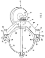
- At least one pivotable throttle valve 9 is arranged within the connecting pipe 7 and is actuated by means of a pressure cell 10.
- the throttle valve 9 comprises a bearing shaft 11, a throttle disk 12 controlling the flow and an actuating lever 13 which is connected to the pressure cell 10 via a linkage 14 (FIG. 2).
- the throttle valve 9 is inserted with the bearing shaft 11 and throttle disk 12 via a slot-like recess 15 in the connecting tube 7; the recess 15 extends transversely to the longitudinal direction BB of the connecting pipe 7.
- the bearing shaft 11 is arranged on the one hand in a first bearing bore 16 of the connecting tube 7 and on the other hand in a second bearing bore 17 of a bearing bracket 18 which closes the recess 15 and by means of screws 19, 20 is held on the connecting pipe 7.
- the bearing bridge 18, which can consist of a plastic or a light metal alloy, has spaced-apart fastening eyes 21, which are brought up to receptacles 23, 24 of the connecting tube 7.
- the screws 19, 20 are screwed into the thread 25, 26 of the connecting tube 7.
- the bearing bridge 18 is provided with a section 28 which complements an inner tube wall 27. Free ends 29, 30 of section 28 cover wall regions 31, 32 of connecting tube 7.
- a first sealing membrane 33 is provided on the connecting tube 7, to which a second corresponding sealing membrane 34 of the bearing bracket 18 is guided.
- a sealing body 35 made of elastic and / or dimensionally stable material is provided between the sealing tracks 33, 34. Both sealing sheets 33, 34 have a trapezoidal shape; likewise an outer boundary 36 of the bearing bracket 18.
- the bearing bridge 18 comprises - FIG. 3 - webs 37, 38 which run transversely to the longitudinal direction B - B of the connecting tube 7 and which are stiffened by ribs 39, 40 which run like a grid.
Landscapes
- Engineering & Computer Science (AREA)
- General Engineering & Computer Science (AREA)
- Mechanical Engineering (AREA)
- Chemical & Material Sciences (AREA)
- Combustion & Propulsion (AREA)
- Characterised By The Charging Evacuation (AREA)
- Control Of Throttle Valves Provided In The Intake System Or In The Exhaust System (AREA)
- Lift Valve (AREA)
Applications Claiming Priority (2)
| Application Number | Priority Date | Filing Date | Title |
|---|---|---|---|
| DE4417472A DE4417472A1 (de) | 1994-05-19 | 1994-05-19 | Luftangsauganalge einer mehrzylindrigen Brennkraftmaschine |
| DE4417472 | 1994-05-19 |
Publications (2)
| Publication Number | Publication Date |
|---|---|
| EP0688943A1 true EP0688943A1 (fr) | 1995-12-27 |
| EP0688943B1 EP0688943B1 (fr) | 1998-06-17 |
Family
ID=6518431
Family Applications (1)
| Application Number | Title | Priority Date | Filing Date |
|---|---|---|---|
| EP95106485A Expired - Lifetime EP0688943B1 (fr) | 1994-05-19 | 1995-04-28 | Système d'admission d'air d'un moteur à combustion multicylindrique |
Country Status (5)
| Country | Link |
|---|---|
| US (1) | US5595150A (fr) |
| EP (1) | EP0688943B1 (fr) |
| JP (1) | JPH0849550A (fr) |
| KR (1) | KR950033002A (fr) |
| DE (2) | DE4417472A1 (fr) |
Families Citing this family (9)
| Publication number | Priority date | Publication date | Assignee | Title |
|---|---|---|---|---|
| DE19649148A1 (de) * | 1996-11-27 | 1998-05-28 | Bayerische Motoren Werke Ag | Elektrisch betätigtes Stellorgan, insbesondere für ein Aggregat an einer Brennkraftmaschine |
| US5839405A (en) * | 1997-06-27 | 1998-11-24 | Chrysler Corporation | Single/multi-chamber perforated tube resonator for engine induction system |
| DE19922216A1 (de) * | 1999-05-14 | 2000-11-30 | Mahle Filtersysteme Gmbh | Schallübertragungsvorrichtung für ein Kraftfahrzeug |
| DE29916333U1 (de) * | 1999-09-16 | 2000-01-13 | Montaplast GmbH, 51597 Morsbach | Lagervorrichtung |
| USD444479S1 (en) | 2000-06-30 | 2001-07-03 | Scot M. Pace | Auto air conditioning manifold |
| DE102004002923B4 (de) * | 2004-01-20 | 2016-10-20 | Volkswagen Ag | Brennkraftmaschine mit Trennblech im Ansaugtrakt |
| JP4625379B2 (ja) * | 2005-07-04 | 2011-02-02 | 株式会社ケーヒン | エンジン用吸気制御装置 |
| US7690478B2 (en) * | 2006-09-15 | 2010-04-06 | Visteon Global Technologies, Inc. | Continuously variable tuned resonator |
| US8456301B2 (en) * | 2007-05-08 | 2013-06-04 | Abbott Diabetes Care Inc. | Analyte monitoring system and methods |
Citations (7)
| Publication number | Priority date | Publication date | Assignee | Title |
|---|---|---|---|---|
| US3840042A (en) * | 1973-02-26 | 1974-10-08 | B Brundage | Butterfly valve |
| DE2932089A1 (de) * | 1979-08-08 | 1981-02-26 | Linde Ag | Absperrvorrichtung |
| GB2096740A (en) * | 1981-04-11 | 1982-10-20 | Rohr Ed Ag | Throttling device for pipe conduits |
| EP0167794A1 (fr) * | 1984-07-03 | 1986-01-15 | Dr.Ing.h.c. F. Porsche Aktiengesellschaft | Dispositif d'admission d'air pour moteur à combustion interne à plusieurs cylindres |
| JPS62101821A (ja) * | 1985-10-29 | 1987-05-12 | Honda Motor Co Ltd | 多気筒エンジンの吸気装置 |
| EP0223378A2 (fr) * | 1985-10-04 | 1987-05-27 | Mazda Motor Corporation | Système d'admission pour moteurs à combustion interne à cylindres en V |
| DE4315129A1 (de) * | 1993-05-07 | 1994-11-17 | Porsche Ag | Luftansaugsystem einer Brennkraftmaschine |
Family Cites Families (8)
| Publication number | Priority date | Publication date | Assignee | Title |
|---|---|---|---|---|
| DE3561900D1 (en) * | 1984-03-10 | 1988-04-21 | Porsche Ag | Air inlet pipe arrangement for a multicylinder internal combustion engine |
| US4803961A (en) * | 1985-11-19 | 1989-02-14 | Mazda Motor Corporation | Air suction devices for multicylinder engines |
| DE3711859C2 (de) * | 1986-04-19 | 2003-04-17 | Volkswagen Ag | Mehrzylindrige Hubkolben-Brennkraftmaschine |
| JPH0656104B2 (ja) * | 1989-05-29 | 1994-07-27 | 本田技研工業株式会社 | 多気筒内燃機関の吸気装置 |
| JP2772674B2 (ja) * | 1989-06-05 | 1998-07-02 | 本田技研工業株式会社 | V型多気筒内燃機関における吸気装置 |
| JPH0739812B2 (ja) * | 1989-08-31 | 1995-05-01 | 本田技研工業株式会社 | V型6気筒内燃機関の吸気制御方法 |
| AT404161B (de) * | 1989-10-16 | 1998-09-25 | Avl Verbrennungskraft Messtech | Ansaugsystem für mehrzylinder-hubkolben- brennkraftmaschinen |
| JPH0431623A (ja) * | 1990-05-28 | 1992-02-03 | Mazda Motor Corp | エンジンの吸気装置 |
-
1994
- 1994-05-19 DE DE4417472A patent/DE4417472A1/de not_active Withdrawn
-
1995
- 1995-04-28 EP EP95106485A patent/EP0688943B1/fr not_active Expired - Lifetime
- 1995-04-28 DE DE59502562T patent/DE59502562D1/de not_active Expired - Fee Related
- 1995-05-16 JP JP7117528A patent/JPH0849550A/ja not_active Withdrawn
- 1995-05-18 US US08/444,102 patent/US5595150A/en not_active Expired - Fee Related
- 1995-05-18 KR KR1019950012362A patent/KR950033002A/ko not_active Withdrawn
Patent Citations (7)
| Publication number | Priority date | Publication date | Assignee | Title |
|---|---|---|---|---|
| US3840042A (en) * | 1973-02-26 | 1974-10-08 | B Brundage | Butterfly valve |
| DE2932089A1 (de) * | 1979-08-08 | 1981-02-26 | Linde Ag | Absperrvorrichtung |
| GB2096740A (en) * | 1981-04-11 | 1982-10-20 | Rohr Ed Ag | Throttling device for pipe conduits |
| EP0167794A1 (fr) * | 1984-07-03 | 1986-01-15 | Dr.Ing.h.c. F. Porsche Aktiengesellschaft | Dispositif d'admission d'air pour moteur à combustion interne à plusieurs cylindres |
| EP0223378A2 (fr) * | 1985-10-04 | 1987-05-27 | Mazda Motor Corporation | Système d'admission pour moteurs à combustion interne à cylindres en V |
| JPS62101821A (ja) * | 1985-10-29 | 1987-05-12 | Honda Motor Co Ltd | 多気筒エンジンの吸気装置 |
| DE4315129A1 (de) * | 1993-05-07 | 1994-11-17 | Porsche Ag | Luftansaugsystem einer Brennkraftmaschine |
Non-Patent Citations (1)
| Title |
|---|
| PATENT ABSTRACTS OF JAPAN vol. 11, no. 318 (M - 632)<2765> 16 October 1987 (1987-10-16) * |
Also Published As
| Publication number | Publication date |
|---|---|
| JPH0849550A (ja) | 1996-02-20 |
| EP0688943B1 (fr) | 1998-06-17 |
| DE59502562D1 (de) | 1998-07-23 |
| US5595150A (en) | 1997-01-21 |
| DE4417472A1 (de) | 1995-11-30 |
| KR950033002A (ko) | 1995-12-22 |
Similar Documents
| Publication | Publication Date | Title |
|---|---|---|
| EP0717815B1 (fr) | Dispositif d'etranglement | |
| EP0726388B1 (fr) | Dispositif d'admission | |
| EP0725210B1 (fr) | Module d'aspiration | |
| WO1995006807A1 (fr) | Dispositif d'etranglement | |
| WO1994004803A1 (fr) | Ensemble collecteur d'admission pour moteurs a combustion interne a cylindres multiples | |
| WO2001009493A2 (fr) | Ensemble collecteur d'admission | |
| EP0688943A1 (fr) | Système d'admission d'air d'un moteur à combustion multicylindrique | |
| EP0365862B1 (fr) | Dispositif pour la recirculation de gaz d'échappement pour un moteur diesel multicylindre | |
| EP1200722B1 (fr) | Dispositif d'etranglement a volet destine au montage dans une jonction a brides | |
| DE202007013151U1 (de) | Ansaugsystem für eine Brennkraftmaschine | |
| DE3843509C2 (de) | Ansaugsystem für eine Brennkraftmaschine | |
| DE10014282A1 (de) | Ansaugvorrichtung mit Schwingrohren und längenverstellbaren Resonanzrohren | |
| DE69000139T2 (de) | Einlassvorrichtung fuer brennkraftmaschine. | |
| DE102007004264A1 (de) | Brennkraftmaschine | |
| DE102004029746B4 (de) | Sauganlage für eine Brennkraftmaschine mit mindestens zwei Zylinderbankreihen | |
| EP1299627A1 (fr) | Volet de commande | |
| DE102004009502B3 (de) | Klappensystem, insbesondere zur Änderung der Strömungsverhältnisse an Einlassventilen | |
| WO1997021025A2 (fr) | Dispositif d'aspiration d'air d'un moteur a combustion interne | |
| DE19709882B4 (de) | Schaltwalze | |
| DE19526241B4 (de) | Lufteinlaßkanalsystem für Brennkraftmaschinen | |
| EP1251253A2 (fr) | Système de soupapes pour fermeture des conduits d'admission d'un système d'admission | |
| EP0868598A1 (fr) | Systeme d'aspiration d'air a longueur variable du tuyau d'aspiration pour moteur a combustion interne | |
| DE102008055628A1 (de) | Verfahren zur Herstellung eines Klappenverbandes | |
| DE3712927A1 (de) | Anordnung von drosselklappen im saugrohr einer brennkraftmaschine | |
| EP3498999B1 (fr) | Soupape pour un système de gaz d'échappement dans un véhicule |
Legal Events
| Date | Code | Title | Description |
|---|---|---|---|
| PUAI | Public reference made under article 153(3) epc to a published international application that has entered the european phase |
Free format text: ORIGINAL CODE: 0009012 |
|
| AK | Designated contracting states |
Kind code of ref document: A1 Designated state(s): DE FR GB IT |
|
| 17P | Request for examination filed |
Effective date: 19960411 |
|
| 17Q | First examination report despatched |
Effective date: 19970408 |
|
| GRAG | Despatch of communication of intention to grant |
Free format text: ORIGINAL CODE: EPIDOS AGRA |
|
| GRAG | Despatch of communication of intention to grant |
Free format text: ORIGINAL CODE: EPIDOS AGRA |
|
| GRAH | Despatch of communication of intention to grant a patent |
Free format text: ORIGINAL CODE: EPIDOS IGRA |
|
| ITF | It: translation for a ep patent filed | ||
| GRAH | Despatch of communication of intention to grant a patent |
Free format text: ORIGINAL CODE: EPIDOS IGRA |
|
| GRAA | (expected) grant |
Free format text: ORIGINAL CODE: 0009210 |
|
| AK | Designated contracting states |
Kind code of ref document: B1 Designated state(s): DE FR GB IT |
|
| GBT | Gb: translation of ep patent filed (gb section 77(6)(a)/1977) |
Effective date: 19980623 |
|
| REF | Corresponds to: |
Ref document number: 59502562 Country of ref document: DE Date of ref document: 19980723 |
|
| ET | Fr: translation filed | ||
| PLBE | No opposition filed within time limit |
Free format text: ORIGINAL CODE: 0009261 |
|
| STAA | Information on the status of an ep patent application or granted ep patent |
Free format text: STATUS: NO OPPOSITION FILED WITHIN TIME LIMIT |
|
| PGFP | Annual fee paid to national office [announced via postgrant information from national office to epo] |
Ref country code: GB Payment date: 19990428 Year of fee payment: 5 |
|
| PGFP | Annual fee paid to national office [announced via postgrant information from national office to epo] |
Ref country code: FR Payment date: 19990429 Year of fee payment: 5 |
|
| 26N | No opposition filed | ||
| PGFP | Annual fee paid to national office [announced via postgrant information from national office to epo] |
Ref country code: DE Payment date: 20000411 Year of fee payment: 6 |
|
| PG25 | Lapsed in a contracting state [announced via postgrant information from national office to epo] |
Ref country code: GB Free format text: LAPSE BECAUSE OF NON-PAYMENT OF DUE FEES Effective date: 20000428 |
|
| GBPC | Gb: european patent ceased through non-payment of renewal fee |
Effective date: 20000428 |
|
| PG25 | Lapsed in a contracting state [announced via postgrant information from national office to epo] |
Ref country code: FR Free format text: LAPSE BECAUSE OF NON-PAYMENT OF DUE FEES Effective date: 20001229 |
|
| REG | Reference to a national code |
Ref country code: FR Ref legal event code: ST |
|
| PG25 | Lapsed in a contracting state [announced via postgrant information from national office to epo] |
Ref country code: DE Free format text: LAPSE BECAUSE OF NON-PAYMENT OF DUE FEES Effective date: 20020201 |
|
| PG25 | Lapsed in a contracting state [announced via postgrant information from national office to epo] |
Ref country code: IT Free format text: LAPSE BECAUSE OF NON-PAYMENT OF DUE FEES Effective date: 20050428 |