EP0688955A1 - Dispositif pour l'équilibrage de la poussée axiale dans les pompes centrifuges - Google Patents
Dispositif pour l'équilibrage de la poussée axiale dans les pompes centrifuges Download PDFInfo
- Publication number
- EP0688955A1 EP0688955A1 EP95108418A EP95108418A EP0688955A1 EP 0688955 A1 EP0688955 A1 EP 0688955A1 EP 95108418 A EP95108418 A EP 95108418A EP 95108418 A EP95108418 A EP 95108418A EP 0688955 A1 EP0688955 A1 EP 0688955A1
- Authority
- EP
- European Patent Office
- Prior art keywords
- impeller
- housing
- housing wall
- gap
- ribs
- Prior art date
- Legal status (The legal status is an assumption and is not a legal conclusion. Google has not performed a legal analysis and makes no representation as to the accuracy of the status listed.)
- Granted
Links
- 238000007789 sealing Methods 0.000 claims abstract description 17
- 238000010586 diagram Methods 0.000 description 5
- 238000003801 milling Methods 0.000 description 2
- 238000000418 atomic force spectrum Methods 0.000 description 1
- 230000001419 dependent effect Effects 0.000 description 1
- 230000003993 interaction Effects 0.000 description 1
- 238000004519 manufacturing process Methods 0.000 description 1
- 230000000750 progressive effect Effects 0.000 description 1
- 230000007704 transition Effects 0.000 description 1
Images


Classifications
-
- F—MECHANICAL ENGINEERING; LIGHTING; HEATING; WEAPONS; BLASTING
- F04—POSITIVE - DISPLACEMENT MACHINES FOR LIQUIDS; PUMPS FOR LIQUIDS OR ELASTIC FLUIDS
- F04D—NON-POSITIVE-DISPLACEMENT PUMPS
- F04D29/00—Details, component parts, or accessories
- F04D29/04—Shafts or bearings, or assemblies thereof
- F04D29/041—Axial thrust balancing
- F04D29/0416—Axial thrust balancing balancing pistons
-
- F—MECHANICAL ENGINEERING; LIGHTING; HEATING; WEAPONS; BLASTING
- F04—POSITIVE - DISPLACEMENT MACHINES FOR LIQUIDS; PUMPS FOR LIQUIDS OR ELASTIC FLUIDS
- F04D—NON-POSITIVE-DISPLACEMENT PUMPS
- F04D29/00—Details, component parts, or accessories
- F04D29/08—Sealings
- F04D29/16—Sealings between pressure and suction sides
- F04D29/165—Sealings between pressure and suction sides especially adapted for liquid pumps
- F04D29/167—Sealings between pressure and suction sides especially adapted for liquid pumps of a centrifugal flow wheel
Definitions
- a device for complete compensation of the axial thrust in centrifugal pumps which, in addition to hydraulic axial thrust compensation, which operates in a conventional manner, has a second, likewise hydraulically acting compensation system.
- This second system is based on means that a pressure increase in the pressure side space of the impeller at one under cause the predetermined value to drop. Since it is not dependent on the pump head as an effective parameter, it can independently compensate for the axial forces even with small heads.
- the present invention also aims at a complete hydraulic compensation of the axial thrust. However, it takes a different path than the facility described above.
- variable sealing gap which has control behavior, is formed by an axial gap between the suction-side end face of the impeller and the housing wall.
- An alternative embodiment provides a variable sealing gap in the form of a diagonal gap.
- the housing ribs and the paragraphs closest to them on the housing wall are designed to be directly adjacent to one another.
- the individual features of the invention are known in principle. However, they have so far been used in combinations other than those according to the invention, in each case still requiring an axial bearing, at least as an emergency bearing.
- the invention makes an axial bearing dispensable because the rotor, i.e. the unit formed from the impeller, the shaft and the rotor of the driving electric motor, is fixed in an axially contact-free manner and, when deflected from this equilibrium position, is returned to its original position without axial force by high restoring forces becomes.
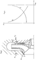
- an angular sealing gap which is formed from a variable axial gap 3 between the end face 4 of the impeller 2 and the housing wall 5 opposite it and a radial gap 6 of constant width between the impeller neck 7 and the housing wall 5 surrounding it.
- Radial sealing gaps 8 and 9 which are formed between a circular and concentric to the axis of the impeller 2 paragraph 10 on the pressure side cover plate 11 of the impeller 2 and paragraphs 12 and 13 on the opposite housing wall 5; a plurality of radially extending housing ribs 14 which are evenly distributed over the circumference and which are delimited radially by the shoulder 13 arranged on a larger diameter and a shoulder 15 provided on a smaller diameter; a variable axial gap 16, which is formed between the shoulder 15 and the pressure-side cover plate 11.
- relief bores 17 are provided, which are arranged in the vicinity of the hub of the impeller 2.
- FIG. 2 essentially corresponds to the embodiment of FIG. 1, the only difference is the suction-side sealing gap, which is designed as a diagonal gap 18 in the device in FIG. 2.
- the advantage of the diagonal gap 18 over the angular gap consisting of the axial gap 3 and the radial gap 6 lies in its better control behavior, as can also be seen from the diagrams in FIGS. 3 and 4.
- the disadvantage is the more complex manufacture of a diagonal gap.
- Figures 3 and 4 already mentioned show the variable forces assigned to the axial movement path s of the impeller 2, the force F2 acting on the pressure side and the force F1 acting on the suction side of the impeller 2.
- the maximum movement path s max should be between 0.8 and 1.2 mm.
- a stable equilibrium position of the rotor is established by coordinating the elements of the axial thrust compensation with one another, i.e. the position and play of the sealing gaps 3, 6, 8, 9, 16, 18 and the position and size of the housing ribs 14 and the relief bores 17 . This fixes the rotor axially without contact during rotation. When deflected from the equilibrium position, relatively high restoring forces ensure that the rotor returns to its original position, which is free of axial force.
- the diagonal gap 18 on the suction side is superior to the combination of the axial gap 3 and the radial gap 6 in its control behavior acting on the axial thrust compensation.
- the device according to the invention can also be realized with a combination of radial (8, 9) and diagonal (22, 23) sealing gaps. Likewise, more than two such sealing gaps (8, 9; 22, 23) can be provided on the pressure side of the impeller (2).
- the housing ribs 14 of the exemplary embodiments were created by milling out the free spaces between the ribs. As a result, the free space areas of paragraphs 13 and 15 were created. It should be mentioned that milling out with a finger cutter results in an arcuate transition of the housing ribs 14 to the walls of the shoulders 13, 15. In a borderline case applicable to short housing ribs, the outer contour of a rib can be semicircular concave on both sides. This has no negative influence on the control behavior of the housing ribs.
Landscapes
- Engineering & Computer Science (AREA)
- Mechanical Engineering (AREA)
- General Engineering & Computer Science (AREA)
- Structures Of Non-Positive Displacement Pumps (AREA)
- Control Of Non-Positive-Displacement Pumps (AREA)
Applications Claiming Priority (2)
| Application Number | Priority Date | Filing Date | Title |
|---|---|---|---|
| DE4421888 | 1994-06-23 | ||
| DE4421888A DE4421888A1 (de) | 1994-06-23 | 1994-06-23 | Einrichtung zum Axialschubausgleich bei Kreiselpumpen |
Publications (2)
| Publication Number | Publication Date |
|---|---|
| EP0688955A1 true EP0688955A1 (fr) | 1995-12-27 |
| EP0688955B1 EP0688955B1 (fr) | 1999-12-29 |
Family
ID=6521263
Family Applications (1)
| Application Number | Title | Priority Date | Filing Date |
|---|---|---|---|
| EP95108418A Expired - Lifetime EP0688955B1 (fr) | 1994-06-23 | 1995-06-01 | Dispositif pour l'équilibrage de la poussée axiale dans les pompes centrifuges |
Country Status (2)
| Country | Link |
|---|---|
| EP (1) | EP0688955B1 (fr) |
| DE (2) | DE4421888A1 (fr) |
Cited By (9)
| Publication number | Priority date | Publication date | Assignee | Title |
|---|---|---|---|---|
| DE19804768A1 (de) * | 1998-02-06 | 1999-08-12 | Pfeiffer Vacuum Gmbh | Rotorlagerung für eine Gasreibungspumpe |
| EP0952352A3 (fr) * | 1998-04-20 | 2001-05-30 | Nikkiso Co., Ltd. | Equilibrage de poussée axiale |
| EP1296062A1 (fr) * | 2001-09-20 | 2003-03-26 | Grundfos a/s | Pompe centrifugale |
| EP1306557A3 (fr) * | 2001-07-13 | 2004-01-07 | Abs Pump Production Ab | Pompe centrifugale |
| GB2442320A (en) * | 2006-09-28 | 2008-04-02 | Snecma | Pump with axial balancing |
| WO2012061011A3 (fr) * | 2010-10-25 | 2012-06-28 | Dresser-Rand Company | Système et appareil permettant de réduire les forces de poussée qui agissent sur un rotor de compresseur |
| CN103850947A (zh) * | 2012-11-29 | 2014-06-11 | 上海凯士比泵有限公司 | 一种抗汽蚀叶片泵 |
| KR101700332B1 (ko) * | 2015-07-29 | 2017-02-14 | 한국해양대학교 산학협력단 | 반경류 터빈의 추력감소 장치 |
| CN115306759A (zh) * | 2022-08-27 | 2022-11-08 | 浙江理工大学 | 一种高速离心泵轴向力平衡结构及其预测方法 |
Families Citing this family (4)
| Publication number | Priority date | Publication date | Assignee | Title |
|---|---|---|---|---|
| DE102016220976B3 (de) | 2016-10-25 | 2018-03-29 | Engineering Center Steyr Gmbh & Co. Kg | Modul für ein Kühlsystem eines Kraftfahrzeugs |
| DE102017211940A1 (de) * | 2017-07-12 | 2019-01-17 | Bayerische Motoren Werke Aktiengesellschaft | Brennstoffzellensystem für ein Kraftfahrzeug sowie Strömungsmaschine für ein Brennstoffzellensystem |
| LU500893B1 (de) * | 2021-11-24 | 2023-05-24 | Wilo Se | Axiallagerlose Nassläuferpumpe |
| DE102024204730A1 (de) * | 2024-05-23 | 2025-11-27 | Robert Bosch Gesellschaft mit beschränkter Haftung | Bauraumoptimierte Integration eines Impellers in eine Doppel-Axialkolbenmaschine in Back-to-back Ausführung |
Citations (4)
| Publication number | Priority date | Publication date | Assignee | Title |
|---|---|---|---|---|
| FR413135A (fr) * | 1910-02-07 | 1910-08-01 | Farcot Freres Et Cie Soc | Dispositif d'équilibrage des pompes centrifuges |
| FR500808A (fr) * | 1919-06-18 | 1920-03-25 | Eugene Beaudrey | Système pour la réalisation de l'équilibre axial des roues de turbines hydrauliques ou pompes centrifuges |
| FR518914A (fr) * | 1914-07-06 | 1921-06-02 | Jean Guerin | équilibrage automatique de la poussée axiale |
| DE4026905A1 (de) | 1990-08-25 | 1992-02-27 | Klein Schanzlin & Becker Ag | Axialschubausgleich fuer kreiselpumpen |
Family Cites Families (6)
| Publication number | Priority date | Publication date | Assignee | Title |
|---|---|---|---|---|
| DE390366C (de) * | 1924-02-18 | Paul Joseph Charles Marechal | Entlastungsvorrichtung an Turbomaschinen | |
| DE325196C (de) * | 1920-09-14 | Aeg | Achsialdruckausgleichvorrichtung fuer Zentrifugalpumpen | |
| JPS4938641B1 (fr) * | 1970-08-06 | 1974-10-19 | ||
| DE2640990A1 (de) * | 1976-09-11 | 1978-03-16 | Klein Schanzlin & Becker Ag | Kreiselpumpe mit selbsttaetiger axialschubregelung an einem der laufraeder |
| DE2733631A1 (de) * | 1977-07-26 | 1979-02-08 | Hermetic Pumpen Gmbh | Kreiselpumpe |
| SE509487C2 (sv) * | 1991-03-22 | 1999-02-01 | Warman Int Ltd | Centrifugalpump |
-
1994
- 1994-06-23 DE DE4421888A patent/DE4421888A1/de not_active Withdrawn
-
1995
- 1995-06-01 DE DE59507508T patent/DE59507508D1/de not_active Expired - Lifetime
- 1995-06-01 EP EP95108418A patent/EP0688955B1/fr not_active Expired - Lifetime
Patent Citations (4)
| Publication number | Priority date | Publication date | Assignee | Title |
|---|---|---|---|---|
| FR413135A (fr) * | 1910-02-07 | 1910-08-01 | Farcot Freres Et Cie Soc | Dispositif d'équilibrage des pompes centrifuges |
| FR518914A (fr) * | 1914-07-06 | 1921-06-02 | Jean Guerin | équilibrage automatique de la poussée axiale |
| FR500808A (fr) * | 1919-06-18 | 1920-03-25 | Eugene Beaudrey | Système pour la réalisation de l'équilibre axial des roues de turbines hydrauliques ou pompes centrifuges |
| DE4026905A1 (de) | 1990-08-25 | 1992-02-27 | Klein Schanzlin & Becker Ag | Axialschubausgleich fuer kreiselpumpen |
Non-Patent Citations (1)
| Title |
|---|
| "centrifugal pump lexicon", KLEIN,SCHANZLIN & BECKER * |
Cited By (14)
| Publication number | Priority date | Publication date | Assignee | Title |
|---|---|---|---|---|
| DE19804768A1 (de) * | 1998-02-06 | 1999-08-12 | Pfeiffer Vacuum Gmbh | Rotorlagerung für eine Gasreibungspumpe |
| DE19804768B4 (de) * | 1998-02-06 | 2006-08-24 | Pfeiffer Vacuum Gmbh | Rotorlagerung für eine Gasreibungspumpe |
| EP0952352A3 (fr) * | 1998-04-20 | 2001-05-30 | Nikkiso Co., Ltd. | Equilibrage de poussée axiale |
| EP1306557A3 (fr) * | 2001-07-13 | 2004-01-07 | Abs Pump Production Ab | Pompe centrifugale |
| EP1296062A1 (fr) * | 2001-09-20 | 2003-03-26 | Grundfos a/s | Pompe centrifugale |
| FR2906578A1 (fr) * | 2006-09-28 | 2008-04-04 | Snecma Sa | Pompe comprenant un systeme d'equilibrage axial |
| GB2442320A (en) * | 2006-09-28 | 2008-04-02 | Snecma | Pump with axial balancing |
| US7686572B2 (en) | 2006-09-28 | 2010-03-30 | Snecma | Pump comprising an axial balancing system |
| GB2442320B (en) * | 2006-09-28 | 2011-09-07 | Snecma | Pump comprising an axial balancing system |
| WO2012061011A3 (fr) * | 2010-10-25 | 2012-06-28 | Dresser-Rand Company | Système et appareil permettant de réduire les forces de poussée qui agissent sur un rotor de compresseur |
| CN103850947A (zh) * | 2012-11-29 | 2014-06-11 | 上海凯士比泵有限公司 | 一种抗汽蚀叶片泵 |
| CN103850947B (zh) * | 2012-11-29 | 2017-03-08 | 上海凯士比泵有限公司 | 一种抗汽蚀叶片泵 |
| KR101700332B1 (ko) * | 2015-07-29 | 2017-02-14 | 한국해양대학교 산학협력단 | 반경류 터빈의 추력감소 장치 |
| CN115306759A (zh) * | 2022-08-27 | 2022-11-08 | 浙江理工大学 | 一种高速离心泵轴向力平衡结构及其预测方法 |
Also Published As
| Publication number | Publication date |
|---|---|
| DE59507508D1 (de) | 2000-02-03 |
| DE4421888A1 (de) | 1996-01-04 |
| EP0688955B1 (fr) | 1999-12-29 |
Similar Documents
| Publication | Publication Date | Title |
|---|---|---|
| DE69313693T2 (de) | Heckrotor eines Drehflügelflugzeuges | |
| EP0392146B1 (fr) | Cage de palier à roulement | |
| DE2328149C2 (de) | Hubschrauberrotor | |
| EP0688955B1 (fr) | Dispositif pour l'équilibrage de la poussée axiale dans les pompes centrifuges | |
| DE3021189A1 (de) | Drehschwingungsdaempfer | |
| DE3306345C2 (fr) | ||
| WO2008034768A1 (fr) | Accouplement d'arbres | |
| DE69104749T2 (de) | Verbesserte Turbomolekularpumpe. | |
| DE3519598A1 (de) | Dichtung, insbesondere waelzlagerdichtung | |
| DE69002816T2 (de) | Anlassvorrichtung mit Planetenuntersetzungsgetriebe. | |
| EP0736692A1 (fr) | Etanchéité, aménagement des paliers et entraînement des rotors d'un compresseur à vis tournant à sec | |
| EP1382797A2 (fr) | Passage d'une machine à écoulement avec étages à contraction augmentée | |
| CH677009A5 (fr) | ||
| DE10338010B3 (de) | Hydrodynamischer Retarder | |
| WO1980000733A1 (fr) | Moteur a vent | |
| DE29715035U1 (de) | Reibungsvakuumpumpe | |
| EP0993552B1 (fr) | Pompe a anneau liquide | |
| DE4414219A1 (de) | Rotor für eine elektrische Maschine | |
| DE2717366A1 (de) | Laufrad fuer eine turbomolekularpumpe | |
| EP1097306B1 (fr) | Moteur oscillant | |
| WO2024017957A1 (fr) | Roue de blocage de stationnement | |
| DD234250A5 (de) | Spannvorrichtung fuer einen schleifring | |
| EP1762737A2 (fr) | Accouplement hydrodynamique | |
| EP3159483A1 (fr) | Dispositif de fixation d'aubes mobiles d'une turbomachine thermique | |
| DE19640734B4 (de) | Axiallager für eine Gliederpumpe |
Legal Events
| Date | Code | Title | Description |
|---|---|---|---|
| PUAI | Public reference made under article 153(3) epc to a published international application that has entered the european phase |
Free format text: ORIGINAL CODE: 0009012 |
|
| AK | Designated contracting states |
Kind code of ref document: A1 Designated state(s): DE DK FR GB |
|
| 17P | Request for examination filed |
Effective date: 19960430 |
|
| 17Q | First examination report despatched |
Effective date: 19970129 |
|
| APAB | Appeal dossier modified |
Free format text: ORIGINAL CODE: EPIDOS NOAPE |
|
| APAB | Appeal dossier modified |
Free format text: ORIGINAL CODE: EPIDOS NOAPE |
|
| APAD | Appeal reference recorded |
Free format text: ORIGINAL CODE: EPIDOS REFNE |
|
| APCB | Communication from the board of appeal sent |
Free format text: ORIGINAL CODE: EPIDOS OBAPE |
|
| APCB | Communication from the board of appeal sent |
Free format text: ORIGINAL CODE: EPIDOS OBAPE |
|
| APAB | Appeal dossier modified |
Free format text: ORIGINAL CODE: EPIDOS NOAPE |
|
| GRAG | Despatch of communication of intention to grant |
Free format text: ORIGINAL CODE: EPIDOS AGRA |
|
| GRAH | Despatch of communication of intention to grant a patent |
Free format text: ORIGINAL CODE: EPIDOS IGRA |
|
| GRAH | Despatch of communication of intention to grant a patent |
Free format text: ORIGINAL CODE: EPIDOS IGRA |
|
| GRAA | (expected) grant |
Free format text: ORIGINAL CODE: 0009210 |
|
| AK | Designated contracting states |
Kind code of ref document: B1 Designated state(s): DE DK FR GB |
|
| PG25 | Lapsed in a contracting state [announced via postgrant information from national office to epo] |
Ref country code: GB Free format text: LAPSE BECAUSE OF FAILURE TO SUBMIT A TRANSLATION OF THE DESCRIPTION OR TO PAY THE FEE WITHIN THE PRESCRIBED TIME-LIMIT Effective date: 19991229 |
|
| REF | Corresponds to: |
Ref document number: 59507508 Country of ref document: DE Date of ref document: 20000203 |
|
| PG25 | Lapsed in a contracting state [announced via postgrant information from national office to epo] |
Ref country code: DK Free format text: LAPSE BECAUSE OF FAILURE TO SUBMIT A TRANSLATION OF THE DESCRIPTION OR TO PAY THE FEE WITHIN THE PRESCRIBED TIME-LIMIT Effective date: 20000329 |
|
| ET | Fr: translation filed | ||
| GBV | Gb: ep patent (uk) treated as always having been void in accordance with gb section 77(7)/1977 [no translation filed] |
Effective date: 19991229 |
|
| PLBE | No opposition filed within time limit |
Free format text: ORIGINAL CODE: 0009261 |
|
| STAA | Information on the status of an ep patent application or granted ep patent |
Free format text: STATUS: NO OPPOSITION FILED WITHIN TIME LIMIT |
|
| 26N | No opposition filed | ||
| APAH | Appeal reference modified |
Free format text: ORIGINAL CODE: EPIDOSCREFNO |
|
| PGFP | Annual fee paid to national office [announced via postgrant information from national office to epo] |
Ref country code: DE Payment date: 20140611 Year of fee payment: 20 |
|
| PGFP | Annual fee paid to national office [announced via postgrant information from national office to epo] |
Ref country code: FR Payment date: 20140623 Year of fee payment: 20 |
|
| REG | Reference to a national code |
Ref country code: DE Ref legal event code: R071 Ref document number: 59507508 Country of ref document: DE |