EP0688970A2 - Hydraulische Bremse für ein Getriebe - Google Patents
Hydraulische Bremse für ein Getriebe Download PDFInfo
- Publication number
- EP0688970A2 EP0688970A2 EP95304375A EP95304375A EP0688970A2 EP 0688970 A2 EP0688970 A2 EP 0688970A2 EP 95304375 A EP95304375 A EP 95304375A EP 95304375 A EP95304375 A EP 95304375A EP 0688970 A2 EP0688970 A2 EP 0688970A2
- Authority
- EP
- European Patent Office
- Prior art keywords
- piston
- assist
- cylinder
- main piston
- frictional engaging
- Prior art date
- Legal status (The legal status is an assumption and is not a legal conclusion. Google has not performed a legal analysis and makes no representation as to the accuracy of the status listed.)
- Granted
Links
- 230000005540 biological transmission Effects 0.000 title claims abstract description 10
- 238000006243 chemical reaction Methods 0.000 claims abstract description 35
- 238000003825 pressing Methods 0.000 claims description 8
- 238000003754 machining Methods 0.000 abstract description 8
- 238000007789 sealing Methods 0.000 description 16
- 230000000717 retained effect Effects 0.000 description 10
- 238000005192 partition Methods 0.000 description 9
- 230000009471 action Effects 0.000 description 8
- 230000007246 mechanism Effects 0.000 description 6
- 238000004891 communication Methods 0.000 description 5
- XEEYBQQBJWHFJM-UHFFFAOYSA-N Iron Chemical compound [Fe] XEEYBQQBJWHFJM-UHFFFAOYSA-N 0.000 description 2
- 239000000969 carrier Substances 0.000 description 2
- 239000000463 material Substances 0.000 description 2
- 229910052751 metal Inorganic materials 0.000 description 2
- 239000002184 metal Substances 0.000 description 2
- 229910052782 aluminium Inorganic materials 0.000 description 1
- XAGFODPZIPBFFR-UHFFFAOYSA-N aluminium Chemical compound [Al] XAGFODPZIPBFFR-UHFFFAOYSA-N 0.000 description 1
- 238000010276 construction Methods 0.000 description 1
- 238000002788 crimping Methods 0.000 description 1
- 238000005520 cutting process Methods 0.000 description 1
- 238000004512 die casting Methods 0.000 description 1
- 230000008030 elimination Effects 0.000 description 1
- 238000003379 elimination reaction Methods 0.000 description 1
- 229910052742 iron Inorganic materials 0.000 description 1
- 238000000034 method Methods 0.000 description 1
- 238000012986 modification Methods 0.000 description 1
- 230000004048 modification Effects 0.000 description 1
- 230000002093 peripheral effect Effects 0.000 description 1
- 230000008569 process Effects 0.000 description 1
- 238000004080 punching Methods 0.000 description 1
- 230000009467 reduction Effects 0.000 description 1
Images


Classifications
-
- F—MECHANICAL ENGINEERING; LIGHTING; HEATING; WEAPONS; BLASTING
- F16—ENGINEERING ELEMENTS AND UNITS; GENERAL MEASURES FOR PRODUCING AND MAINTAINING EFFECTIVE FUNCTIONING OF MACHINES OR INSTALLATIONS; THERMAL INSULATION IN GENERAL
- F16D—COUPLINGS FOR TRANSMITTING ROTATION; CLUTCHES; BRAKES
- F16D65/00—Parts or details
- F16D65/14—Actuating mechanisms for brakes; Means for initiating operation at a predetermined position
- F16D65/16—Actuating mechanisms for brakes; Means for initiating operation at a predetermined position arranged in or on the brake
- F16D65/18—Actuating mechanisms for brakes; Means for initiating operation at a predetermined position arranged in or on the brake adapted for drawing members together, e.g. for disc brakes
- F16D65/186—Actuating mechanisms for brakes; Means for initiating operation at a predetermined position arranged in or on the brake adapted for drawing members together, e.g. for disc brakes with full-face force-applying member, e.g. annular
-
- F—MECHANICAL ENGINEERING; LIGHTING; HEATING; WEAPONS; BLASTING
- F16—ENGINEERING ELEMENTS AND UNITS; GENERAL MEASURES FOR PRODUCING AND MAINTAINING EFFECTIVE FUNCTIONING OF MACHINES OR INSTALLATIONS; THERMAL INSULATION IN GENERAL
- F16D—COUPLINGS FOR TRANSMITTING ROTATION; CLUTCHES; BRAKES
- F16D55/00—Brakes with substantially-radial braking surfaces pressed together in axial direction, e.g. disc brakes
- F16D55/24—Brakes with substantially-radial braking surfaces pressed together in axial direction, e.g. disc brakes with a plurality of axially-movable discs, lamellae, or pads, pressed from one side towards an axially-located member
- F16D55/26—Brakes with substantially-radial braking surfaces pressed together in axial direction, e.g. disc brakes with a plurality of axially-movable discs, lamellae, or pads, pressed from one side towards an axially-located member without self-tightening action
- F16D55/36—Brakes with a plurality of rotating discs all lying side by side
- F16D55/40—Brakes with a plurality of rotating discs all lying side by side actuated by a fluid-pressure device arranged in or one the brake
-
- F—MECHANICAL ENGINEERING; LIGHTING; HEATING; WEAPONS; BLASTING
- F16—ENGINEERING ELEMENTS AND UNITS; GENERAL MEASURES FOR PRODUCING AND MAINTAINING EFFECTIVE FUNCTIONING OF MACHINES OR INSTALLATIONS; THERMAL INSULATION IN GENERAL
- F16D—COUPLINGS FOR TRANSMITTING ROTATION; CLUTCHES; BRAKES
- F16D55/00—Brakes with substantially-radial braking surfaces pressed together in axial direction, e.g. disc brakes
- F16D2055/0004—Parts or details of disc brakes
- F16D2055/0058—Fully lined, i.e. braking surface extending over the entire disc circumference
-
- F—MECHANICAL ENGINEERING; LIGHTING; HEATING; WEAPONS; BLASTING
- F16—ENGINEERING ELEMENTS AND UNITS; GENERAL MEASURES FOR PRODUCING AND MAINTAINING EFFECTIVE FUNCTIONING OF MACHINES OR INSTALLATIONS; THERMAL INSULATION IN GENERAL
- F16D—COUPLINGS FOR TRANSMITTING ROTATION; CLUTCHES; BRAKES
- F16D2121/00—Type of actuator operation force
- F16D2121/02—Fluid pressure
Definitions
- the present invention relates to a hydraulic brake for a transmission, including an assist piston, a reaction piston and a main piston which are disposed within a cylinder. so that the hydraulic pressure is boosted by these pistons, and a plurality of frictional engaging elements are brought into pressing contact with one another by such hydraulic pressure to couple a rotatable member to a stationary member.
- Such a hydraulic brake for a transmission is known from Japanese Patent Publication No. 43908/83.
- a hydraulic brake for a transmission comprising, an assist piston, a reaction piston and a main piston which are axially disposed within a cylinder sequentially in the named order, such that a first frictional engaging element supported on a rotatable member and a second frictional engaging element supported on a stationary member are brought into pressing contact with each other to couple said rotatable member to said stationary member, said assist piston defining a first oil chamber between a rear end of the assist piston and said cylinder, and having a first acting portion at a front portion of the assist piston for engaging and urging a rear portion of said main piston, said reaction piston being substantially fixed relative to said cylinder, said assist piston and said main piston being axially slidable relative to said reaction piston, said main piston defining a second oil chamber between a rear portion of the main piston and said reaction piston to communicate with said first oil chamber, and having a second acting portion at a front portion of the main piston for bringing said first and second frictional
- each of the pistons can be smoothly slid axially while preventing the generation of a jarring, thereby reliably bringing the first and second frictional engaging elements into pressing contact with each other.
- the hydraulic brake may further include a frictional engaging element holder which is provided with a cylinder supporting portion for supporting the cylinder. and with a guide arm for guiding said first and second frictional engaging elements, and said guide arm may be provided at a tip end thereof with a locking portion for preventing the disassembly of said first and second frictional engaging elements.
- An oil passageway for connecting the first and second oil chambers to each other may be comprised of a first oil passage defined between the cylinder and the assist piston, and a second oil passage defined between the assist piston and the main piston.
- a main shaft 4 is disposed within a casing 1 and a cover 3 is coupled to the casing 1 by bolts 2.
- the main shaft 4 is connected to an engine through a torque converter (both not shown) and driven for rotation.
- a first planetary gear mechanism P1 of a single planetary gear type and a second planetary gear mechanism P2 of a double planetary gear type are axially juxtaposed around an outer periphery of the main shaft 4.
- the first planetary gear mechanism P1 and the second planetary gear mechanism P2 include sun gears 61, 62, planetary carriers 71, 72 and ring gears 81 and 82, respectively.
- the planetary carriers 71, 72 are integrally coupled to each other, and the ring gears 81 and 82 are integrally formed on an inner periphery of a ring gear carrying member 8.
- a plurality of planetary gears 101 are carried on the planetary carrier 71 and meshed simultaneously with the sun gear 61 and the ring gear 81.
- a plurality of inner planetary gears 102 are carried on the planetary carrier 72 and meshed with the sun gear 62.
- a plurality of outer planetary gears 102 are meshed with the ring gear 82.
- the inner and outer planetary gears 102 are meshed with each other (see Fig. 5).
- the ring gear carrying member 8 is supported on a partition wall 11 of the casing 1 with a one-way clutch 12 interposed therebetween and is capable of being coupled to the casing 1 through a hydraulic brake B and to the main shaft 4 through a hydraulic clutch C (partially shown).
- a final drive gear 14 is carried on the partition wall 11 of the casing 1 with a ball bearing 13 interposed therebetween and is spline-coupled to the planetary carrier 72 of the second planetary gear mechanism P2.
- the sun gear 62 of the second planetary gear mechanism P2 is spline-coupled to a sleeve 15 which is disposed between the outer periphery of the main shaft 4 and an inner periphery of the final drive gear 14.
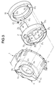
- the hydraulic brake B includes a frictional engaging element holder 21 and a cylinder 22 which are retained on a right side surface of the partition wall 11 of the casing 1 coaxial with the main shaft 4.
- the frictional engaging element holder 21 includes a cylinder supporting portion 211 formed into an annular shape, three guide arms 212 extending axially rightwardly from the cylinder supporting portion 211 at circumferential spacing angles of 120° with respect to one another, and three notches 213 and three flanges 214 integrally formed on a left end of the cylinder supporting portion 211.
- the cylinder 22 is an annular member having a J-shaped section.
- the cylinder 22 is provided at a left end face thereof with a pair of first positioning projections 221, 221, a pair of second positioning projections 222, 222 and an oil hole 223.
- a ball bearing supporting hole 111 for supporting the ball bearing 13
- three projections 112 circumferentially spaced by angles of 120° with respect to one another and extending radially from an outer periphery of the ball bearing supporting hole 111
- an oil hole 113 defined in one of the projections 111
- an oil passage 11 connected to the oil hole 113.
- the pair of first positioning projections 221, 221 of the cylinder 22 are fitted into a pair of positioning holes 215, 215 defined in two of the flanges 214, 214 of the frictional engaging element holder 21, and the pair of second positioning projections 222, 222 of the cylinder 22 are fitted through two of the notches 213, 213 of the frictional engaging element holder 21 into a pair of positioning holes 115, 115 defined in two of the projections 112, 112.
- the three notches 213 of the frictional engaging element holder 21 are fitted to the three projections 112, respectively, whereby the frictional engaging element holder 21 and the cylinder 22 are retained on the partition wall 11.
- the oil hole 113 defined in the partition wall 11 is in communication with the oil hole 223 defined in the cylinder 22 and is sealed by a sealing member 23.
- An assist piston 24, a reaction piston 25 and a main piston 26 are inserted into the cylinder 22 in the named order from a left side toa right side thereof.
- the assist piston 24 is an annular member having a substantially L-shaped section, with its outer periphery being in sliding contact with an inner wall surface of the cylinder 22 through a sealing member 27 (a lip seal).
- a first oil chamber 28 is defined between a left end face of the assist piston 24 and a bottom wall of the cylinder 22, and the oil hole 223 opens into the first oil chamber 28.
- the reaction piston 25 is an annular member having a substantially L-shaped section. An outer periphery of the reaction piston 25 is guided on inner surfaces of the guide arms 212 of the frictional engaging element holder 21, and an inner periphery of the reaction piston 25 is in sliding contact with the assist piston 24 with a sealing member 29 interposed therebetween. A left end face of the reaction piston 25 is abutted against a pressure receiving portion 224 formed on a right end face of the outer periphery of the cylinder 22, and a space 30 is defined between the assist piston 24 and the reaction piston 25. The space 30 is in communication with an internal space within the transmission through a plurality of notches 225 provided in the pressure receiving portion 224 of the cylinder 22.
- the reaction piston 25 is limited in leftward movement by the abutment against the cylinder and is permitted to be only moved leftwardly. However, the reaction piston 25 is biased leftwardly by a return spring (which will be described hereinafter) by hydraulic pressure during actuation of the brake and hence, cannot be moved rightwardly when reaction piston 25 is substantially fixed to the cylinder 22.
- a return spring which will be described hereinafter
- An outer periphery of the annular main piston 26 is in sliding contact with the reaction piston 25 through a sealing member 31 (a lip seal), and an inner periphery of the annular main piston 26 is in sliding contact with an inner wall surface of the cylinder 22 through a sealing member 32.
- a left end face of the main piston 26 is abutted against a first acting portion 241 formed on a right end face of the inner periphery of the assist piston 24, and a second oil chamber 33 is defined between the main piston 26 and the reaction piston 25.
- a second acting portion 261 is formed on a right end face of the main piston 26 which abuts against an end plate which will be described hereinafter.
- a first axially extending oil passage 242 is defined between the cylinder 22 and the assist piston 24, and second oil passages 243 comprising eight notches are formed in the first acting portion 241 of the assist piston 24 which abuts against the main piston 26.
- the first oil chamber 28 is in communication with the second oil chamber 33 through the first oil passage 242 and the second oil passage 243.
- the oil passages i.e., the fist oil passage 242 and the second oil passages 243 permitting the communication between the first and second oil chambers 28 and 33 are provided between assist piston 24 and the main piston 26 and therefore, the need for providing an oil passageway in the casing by machining is eliminated, leading to a reduced machining cost.
- the cylinder 22 is a pressed article made of an iron-based material
- each of the assist piston 24, the reaction piston 25 and the main piston 26 is a die-cast article made of an aluminum-based material.
- five brake disks 41 as first frictional engaging elements are relatively non-rotatably and axially slidably supported in splines 83 formed in an outer periphery of the ring gear carrying member 8.
- Two brake end plates 42, 42 and four brake plates 43 as second frictional engaging elements are alternately superposed on the five brake disks 41.
- a plurality of projections 421 and a plurality of projections 431 are provided on an outer periphery of each of the brake end plates 42 and each of the brake plates 43, respectively, so that the brake end plates 42 and the brake plates 43 are relatively non-rotatably and axially slidably supported in the casing 1 by engagement of these projections 421 and 431 in splines 11 formed in an inner periphery of the casing 1.
- Three guide portions 422 are formed on the outer periphery of each of the brake end plates 42 to come into sliding contact with the three guide arms 212 of the frictional engaging element holder 21, and three pairs of guide portions (six in total) 432 are formed on the outer periphery of each of the brake plates 43 to come into sliding contact with the inner peripheries of the three guide arms 212, respectively.
- the brake end plates 42, 42 and the brake plates 43 mainly receive a torque in a rotating direction by engagement of their projections 421 and 431 in the splines 11 in the casing 1, and are positioned radially by sliding contact of their guide portions 422 and 432 with the inner surfaces of the guide arms 212 of the frictional engaging element holder 21.
- Twelve spring seats 423 are mounted to the outer peripheries of each of the brake end plates 42, and the ends of a pair of return springs 44, 44 that extend between the end plates 42 abut against each of the spring seats 423.
- twelve notches 433 are defined in the outer peripheries of the brake plates 43, and each pair of return springs 44 loosely fit in each of the notches 433.
- Each of the three guide arms 212 of the frictional engaging element holder 21 is provided at its tip end with a radially protruding locking portion 216 formed by cutting and punching the metal. These locking portions 216 are engageable with the right side of the right brake end plate 42 during assembly, as described below.
- a back-up plate 46 is mounted between a left side surface of the cover 2 and the right side surface of the right brake end plate 42 with a shim 45 interposed between the back-up plate 46 itself and the right brake end plate 42.
- the assist piston 24 is moved rightwardly, so that the first acting portion 241 thereof urges the main piston 26 rightwardly.
- the working oil in the first oil chamber 28 is also applied to the second oil chamber 33 through the first oil passage 242 and the second oil passages 243.
- the reaction piston 25 defining the second oil chamber 33 by cooperation with the main piston 26 is in abutment against the pressure receiving portion 22 of the cylinder, whereby the leftward movement of the reaction piston 25 is limited. Therefore, the hydraulic pressure in the second oil chamber 33 urges the main piston 26 rightwardly.
- the brake disks 41 and the brake plates 43 are clamped between the left brake end plate 42 and the right brake end plate 42 whose movement is limited by the back-up plate 46, whereby the ring gear carrying member 8 is frictionally locked to the casing 1.
- the first acting portion 241 of the assist piston 24 and the second acting portion 261 of the main piston 26 are superposed on each other as viewed axially, and therefore, the line of action of the urging force of the first acting portion 241 and a line of action of the urging force of the second acting portion 261 can be substantially aligned with each other to prevent a jarring of the assist piston 24 and the main piston 26.
- the assist piston 24 and the main piston 26 can axially and smoothly slide, thereby reliably bringing the brake disks 41, the brake end plates 42, 42 and the brake plates 43 into pressing contact with one another.
- the abutment portions of the back-up plate 46 and the right brake end plate 42 are located on an extension of the action line of the urging force of the second acting portion 261 for urging the left brake end plate 42 and therefore, the abutments between the brake disks 41, the brake end plate 42, 42 and the brake plates 43 are uniform and aligned to provide an improved durability.
- the hydraulic brake B is subassembled in the following manner into an assembly and then collectively assembled within the casing 1. Namely, the cylinder 22 having assist piston 24, the reaction piston 25 and the main piston 26 incorporated therein is fitted into the cylinder supporting portion 211 of the frictional engaging element holder 1, and then, the left brake end plate 42 is fitted to the guide arms 212 of the frictional engaging element holder 21. Subsequently, the five brake disks 41 and the four brake plates 43 are alternately superposed on one another, and the twenty-four return springs 44 are mounted on the outer periphery of these superposed members. Thereafter, the right brake end plate 42 is fitted to the guide arms 212.
- the locking portions 216 of the guide arms 212 are punched radially inwardly to engage the right side of the right brake end plate 42, thus preventing the disassembly of the aforementioned elements from the frictional engaging element holder 21.
- the locking portions may be precut and punched to allow the elements to be successively snapped into the frictional engaging element holder 21 during assembly.
- the left brake end plate 42 is brought into abutment against the second acting portions 261 of the main piston 26 by preset loads of the return springs 44 and retained axially, and the right brake end plate 42 is brought into abutment against the locking portion 216 of the guide arm 212 and retained radially.
- the four brake plates 43 and two brake end plates 42, 42 are retained radially with their guide portions 432 and 422, respectively, in abutment against the inner surfaces of the guide arms 212. Further, the five brake disks 41 superposed alternately on the two brake end plates 42, 42 and the four brake plates 43 are retained radially with their outer peripheries restrained by the twenty-four return springs 44.
- the hydraulic brake B subassembled in the above-described manner, is inserted through the opening at the right end of the casing 1 into the leftward position.
- the inner peripheries of the brake disks 41 are fitted into the splines 83 in the ring gear carrying member 8, and the outer peripheries of the brake end plates 42, 42 and the brake plates 43 are fitted into the spline 11 in the casing 1.
- the three notches 213 in the frictional engaging element holder 21 are aligned with and fit over the three projections 112 on the casing partition wall 11 with the projections 222 fitted into the positioning holes 115 and the sealing member 23 is installed.
- the back-up plate 46 and the shim 45 are superposed on the right side of the right brake end plate 42, and the cover 3 is mounted to the opening at the right end of the casing 1 and fixed thereto by bolts 2.
- This causes the right brake end plate 42 to be urged leftwardly away from the locking portions 216 of the guide arms 212 by the back-up plate 46.
- the clearances between the brake disks 41, the brake end plates 42, 42 and the brake plates 43 can be adjusted by properly selecting the thickness of the shim 45.
- each of an assist piston 24, a reaction piston 25 and a main piston 26 is formed from pressed articles, such as sheet metal pressed to the desired shape in a die.
- the main piston 26 is comprised of a first piston half 26a and a second piston half 26b, both of which are pressed articles. Projections are provided in an axially protruding fashion on a peripheral edge of the second piston half 26b at three points to abut against a side of the first piston half 26a.
- a sealing member 27 is provided on the assist piston 24 for sealing its surface which is in sliding contact with the cylinder 22. The sealing member 27 is retained by a sealing member holder 51 fixed to the assist piston 24 by crimping.
- a sealing member 29 is retained on the reaction piston 25 by a sealing member holder 52 for sealing the inner surface of the reaction piston 25 which is in sliding contact with the assist piston 24, and two sealing members 31 and 32 are retained on the main piston 26 by sealing member holders 53 and 54 for sealing those surfaces of the main piston 26 which are in sliding contact with the reaction piston 25 and the cylinder 22, respectively.
- the first oil chamber 28 and the second oil chamber 33 are in communication with each other through a first oil passage 242 defined between the cylinder 22 and the assist piston 24 and second oil passage 243 comprised of eight notches formed in the first acting portion 241 of the assist piston 24. Since the assist piston 24 is formed from a pressed article, the first oil passage 242 and the second oil passage 243 can be made simultaneously in the assist piston 24 by a punch press machine, thereby further reducing the machining cost in cooperation with the elimination of the need for providing an oil passageway in the casing 1 by machining.
- the reaction piston 25 and the main piston 26 are formed in a die-casting process, it is necessary to precisely machine the left end face of the main piston 26 abutting against the first action portion 241 or the like.
- the reaction piston 25 and the main piston 26 are formed from pressed articles of a high dimensional accuracy as in the second embodiment, that machining is made unnecessary. This makes it possible not only to reduce the machining cost, but also to assure smooth movements of the pistons 24, 25 and 26.
- the first acting portion 241 of the assist piston 24 and the second acting portion 261 of the main piston 26 are superposed to each other and therefore, the line of action of the urging force of the first acting portion 241 and the line of action of the urging force of the second acting portion 261 can be substantially aligned with each other to prevent the jarring of the assist piston 24 and the main piston 26, and to reliably bring the brake disks 41, the brake end plates 42, 42 and the brake plates 43 into pressing contact with one another.
- the area of the first acting portion 241 of the assist piston 24 is smaller than that of the second acting portion 261 of the main piston 26, and the first acting portion 241 is provided so that it is superposed in the vicinity of the radially inner end of the second acting portion 261.
- the relationships in area magnitude and position between the first and second acting portions 241 and 261 can be changed as desired. Namely, what is important is that the first and second acting portions 241 and 261 are superposed on each other at least partially as viewed axially, i.e. at least a portion of the first and second acting portions are at substantially the same radial distance from main shaft 4.
Landscapes
- Engineering & Computer Science (AREA)
- General Engineering & Computer Science (AREA)
- Mechanical Engineering (AREA)
- Braking Arrangements (AREA)
Applications Claiming Priority (6)
| Application Number | Priority Date | Filing Date | Title |
|---|---|---|---|
| JP140583/94 | 1994-06-22 | ||
| JP14058394 | 1994-06-22 | ||
| JP14058394 | 1994-06-22 | ||
| JP2397095 | 1995-02-13 | ||
| JP2397095A JP3599123B2 (ja) | 1994-06-22 | 1995-02-13 | トランスミッション用油圧ブレーキ |
| JP23970/95 | 1995-02-13 |
Publications (3)
| Publication Number | Publication Date |
|---|---|
| EP0688970A2 true EP0688970A2 (de) | 1995-12-27 |
| EP0688970A3 EP0688970A3 (de) | 1998-09-30 |
| EP0688970B1 EP0688970B1 (de) | 2001-09-19 |
Family
ID=26361421
Family Applications (1)
| Application Number | Title | Priority Date | Filing Date |
|---|---|---|---|
| EP95304375A Expired - Lifetime EP0688970B1 (de) | 1994-06-22 | 1995-06-22 | Hydraulische Bremse für ein Getriebe |
Country Status (4)
| Country | Link |
|---|---|
| US (1) | US5701976A (de) |
| EP (1) | EP0688970B1 (de) |
| JP (1) | JP3599123B2 (de) |
| DE (1) | DE69522750T2 (de) |
Cited By (3)
| Publication number | Priority date | Publication date | Assignee | Title |
|---|---|---|---|---|
| WO2010088986A1 (de) * | 2009-02-07 | 2010-08-12 | Schaeffler Technologies Gmbh & Co. Kg | Druckkolbenanordnung mit losem dichtring |
| WO2012052498A1 (de) * | 2010-10-20 | 2012-04-26 | Stromag Ag | Druckmittelbetätigte reibkupplung oder -bremse |
| WO2012084125A1 (en) * | 2010-12-22 | 2012-06-28 | Schaeffler Technologies AG & Co. KG | Bi-directional clip seal piston |
Families Citing this family (31)
| Publication number | Priority date | Publication date | Assignee | Title |
|---|---|---|---|---|
| JP3221329B2 (ja) * | 1996-10-01 | 2001-10-22 | 日産自動車株式会社 | 自動変速機の回転クラッチ装置 |
| JP3894627B2 (ja) * | 1997-09-11 | 2007-03-22 | 本田技研工業株式会社 | 車両用多板式ブレーキ |
| US6142262A (en) * | 1998-10-21 | 2000-11-07 | Meritor Heavy Vehicle Systems, Llc | Wet disc pack with modified stationary discs |
| US6516924B1 (en) * | 2000-06-12 | 2003-02-11 | Ausco Products, Inc. | Vehicle brake system |
| US6550588B2 (en) * | 2001-07-10 | 2003-04-22 | Caterpillar Inc | Off highway truck brake assembly and wheel spindle having a spline joint |
| JP2003056597A (ja) * | 2001-08-22 | 2003-02-26 | Nsk Warner Kk | 多板クラッチ |
| US20030150674A1 (en) * | 2002-02-13 | 2003-08-14 | White Hydraulics, Inc. | Disk spring hydraulic clutch/brake |
| US6699153B2 (en) * | 2002-04-19 | 2004-03-02 | General Motors Corporation | Electrically-actuated braking clutch for transmission |
| US6684995B1 (en) * | 2002-08-27 | 2004-02-03 | General Motors Corporation | Automatic transmission rotating clutch with no return spring |
| US20040060779A1 (en) * | 2002-10-01 | 2004-04-01 | Charles Kreger | Distance compensating shim for clutch/brake and method of determining same |
| EP1411256B1 (de) * | 2002-10-18 | 2007-09-05 | BorgWarner Inc. | Abschlussscheibe für eine Lamellenanordnung |
| US6920971B2 (en) * | 2003-04-17 | 2005-07-26 | Caterpillar Inc | Cushioned hydraulic clutch/brake piston |
| US7140481B2 (en) * | 2004-06-25 | 2006-11-28 | Freudenberg-Nok General Partnership | Clutch piston amplifier assembly |
| JP4779341B2 (ja) * | 2004-11-18 | 2011-09-28 | トヨタ自動車株式会社 | 自動変速機用ピストン |
| JP5627827B2 (ja) * | 2005-09-02 | 2014-11-19 | ホンマ科学株式会社 | 自由回転環状体型ブレーキ装置 |
| DE102006001895B4 (de) * | 2006-01-14 | 2021-07-01 | Zf Friedrichshafen Ag | Parkbremse für ein Kraftfahrzeug |
| DE102006001893B4 (de) * | 2006-01-14 | 2023-05-11 | Zf Friedrichshafen Ag | Parkbremse für ein Kraftfahrzeug |
| DE102008018210B4 (de) * | 2007-05-02 | 2020-01-09 | Schaeffler Technologies AG & Co. KG | Dichtungsanordnung und nasslaufende Doppelkupplungsanordnung mit einer Dichtungsanordnung |
| EP2217474A1 (de) * | 2007-11-08 | 2010-08-18 | AGCO GmbH | Bremse für ein nutzfahrzeug |
| US8491434B2 (en) | 2010-12-10 | 2013-07-23 | Caterpillar Inc. | Transmission assembly having variable force clutch |
| US8500591B2 (en) * | 2011-01-28 | 2013-08-06 | Deere & Company | Final drive arrangement |
| US9011287B2 (en) | 2012-06-01 | 2015-04-21 | Caterpillar Inc. | Dual piston transmission clutch |
| US9447878B2 (en) * | 2013-05-24 | 2016-09-20 | Schaeffler Technologies AG & Co. KG | Piston seal assembly |
| CN105683606B (zh) * | 2013-11-29 | 2018-01-16 | 爱信艾达株式会社 | 多挡变速器 |
| CN105829774B (zh) * | 2013-12-26 | 2017-10-03 | 爱信艾达株式会社 | 自动变速器的油压控制装置 |
| US9458896B2 (en) | 2014-02-28 | 2016-10-04 | C-Stone Technologies Co., Ltd. | Power transmission device provided with more than two pistons and method of determining return spring force in the same |
| KR101732475B1 (ko) * | 2015-08-12 | 2017-05-08 | 씨스톤 테크놀로지스(주) | 두 개 이상의 피스톤이 구비된 동력 전달 장치 |
| US10215237B2 (en) * | 2016-07-29 | 2019-02-26 | GM Global Technology Operations LLC | Multiple-piece backing plate having parts made of different materials |
| US10132364B2 (en) | 2016-07-29 | 2018-11-20 | GM Global Technology Operations LLC | Backing plate providing axial stiffness |
| US12054005B2 (en) * | 2021-01-11 | 2024-08-06 | Honeywell International Inc. | Wheel and brake assembly with mechanical stop |
| DE102021126110B3 (de) * | 2021-10-08 | 2022-08-18 | Schaeffler Technologies AG & Co. KG | Drehmomentverteileinrichtung und Verfahren zum Betrieb einer Drehmomentverteileinrichtung |
Citations (1)
| Publication number | Priority date | Publication date | Assignee | Title |
|---|---|---|---|---|
| JPH0543908B2 (de) | 1984-08-09 | 1993-07-02 | Aisin Aw Co |
Family Cites Families (11)
| Publication number | Priority date | Publication date | Assignee | Title |
|---|---|---|---|---|
| US2901888A (en) * | 1957-09-20 | 1959-09-01 | Int Harvester Co | Multi-piston servo-motor |
| FR1523402A (fr) * | 1967-03-22 | 1968-05-03 | Hispano Suiza Lallemant Soc | Perfectionnements apportés aux freins à disques multiples, notamment pour roues d'aviation |
| US3547233A (en) * | 1968-09-23 | 1970-12-15 | Minnesota Automotive Inc | Pressure and wear compensator for caliper disk brake |
| GB1271680A (en) * | 1969-07-18 | 1972-04-26 | Borg Warner Ltd | Brake and clutch actuating assembly |
| US3599512A (en) * | 1969-07-29 | 1971-08-17 | Borg Warner | Transmission mechanism |
| US4560034A (en) * | 1982-03-05 | 1985-12-24 | Caterpillar Tractor Co. | Annular multi-piston brake apparatus |
| US4753136A (en) * | 1985-01-19 | 1988-06-28 | Aisin-Warner Limited | Hydraulic control of transmission |
| US4862768A (en) * | 1987-01-06 | 1989-09-05 | Aisin-Warner Kabushiki Kaisha | Limiting/switching device for four wheel drive vehicle |
| JPH0543908A (ja) * | 1991-03-26 | 1993-02-23 | Mitsubishi Materials Corp | 中空素材の製造方法 |
| US5232411A (en) * | 1991-07-26 | 1993-08-03 | Nissan Motor Co., Ltd. | Structure for automatic transmission |
| JP3111768B2 (ja) * | 1993-08-24 | 2000-11-27 | トヨタ自動車株式会社 | 自動変速機の摩擦係合装置 |
-
1995
- 1995-02-13 JP JP2397095A patent/JP3599123B2/ja not_active Expired - Fee Related
- 1995-06-22 EP EP95304375A patent/EP0688970B1/de not_active Expired - Lifetime
- 1995-06-22 US US08/493,481 patent/US5701976A/en not_active Expired - Fee Related
- 1995-06-22 DE DE69522750T patent/DE69522750T2/de not_active Expired - Fee Related
Patent Citations (1)
| Publication number | Priority date | Publication date | Assignee | Title |
|---|---|---|---|---|
| JPH0543908B2 (de) | 1984-08-09 | 1993-07-02 | Aisin Aw Co |
Cited By (5)
| Publication number | Priority date | Publication date | Assignee | Title |
|---|---|---|---|---|
| WO2010088986A1 (de) * | 2009-02-07 | 2010-08-12 | Schaeffler Technologies Gmbh & Co. Kg | Druckkolbenanordnung mit losem dichtring |
| WO2012052498A1 (de) * | 2010-10-20 | 2012-04-26 | Stromag Ag | Druckmittelbetätigte reibkupplung oder -bremse |
| WO2012084125A1 (en) * | 2010-12-22 | 2012-06-28 | Schaeffler Technologies AG & Co. KG | Bi-directional clip seal piston |
| US9410624B2 (en) | 2010-12-22 | 2016-08-09 | Schaeffler Technologies AG & Co. KG | Bi-directional clip seal piston |
| DE112011104521B4 (de) * | 2010-12-22 | 2021-01-14 | Schaeffler Technologies AG & Co. KG | Kolben mit bidirektionaler Klemmdichtung |
Also Published As
| Publication number | Publication date |
|---|---|
| DE69522750T2 (de) | 2002-05-29 |
| EP0688970A3 (de) | 1998-09-30 |
| EP0688970B1 (de) | 2001-09-19 |
| US5701976A (en) | 1997-12-30 |
| DE69522750D1 (de) | 2001-10-25 |
| JP3599123B2 (ja) | 2004-12-08 |
| JPH0868431A (ja) | 1996-03-12 |
Similar Documents
| Publication | Publication Date | Title |
|---|---|---|
| US5701976A (en) | Hydraulic brake for transmission | |
| CN110273947B (zh) | 自动变速器 | |
| JP3585339B2 (ja) | 多板クラッチ | |
| JP3459159B2 (ja) | 板状支持部材のシャフト取付孔加工方法 | |
| EP1769170A2 (de) | Planare kupplungsanordnung für automatikgetriebe | |
| US20060054448A1 (en) | Clutch hub | |
| US6419065B1 (en) | Multi-disk clutch and method of manufacturing a core plate of a multi-disk clutch | |
| US12379003B2 (en) | Clutch with a piston that can be actuated on both sides and mechanical engaging elements | |
| EP1298355B1 (de) | Zylinder für automatisches Getriebe | |
| KR100870220B1 (ko) | 차량용 자동 변속기 | |
| US5913397A (en) | Clutch structure with piston having surface recessed from pressure surface for reducing stress concentration | |
| US3877321A (en) | Transmission having hydraulic preload motor for axially positioning brake components | |
| CN110273937B (zh) | 自动变速器 | |
| US7140483B2 (en) | Transmission parking brake | |
| US5857549A (en) | Torque transmitting device with a lever apply spring | |
| US6588558B2 (en) | Release system for a clutch assembly | |
| US3914849A (en) | Sheet metal piston for transmissions and method of making a piston assembly | |
| US6000514A (en) | Engaging device | |
| JP3497016B2 (ja) | 自動変速機のリテーナ配設構造 | |
| US4881628A (en) | Automatic transmission having coaxially overlapped clutches | |
| WO2021164485A1 (en) | Arrangement for shifting brake device | |
| US3983617A (en) | Sheet metal piston for transmissions and method of making a piston assembly | |
| JPH0979289A (ja) | 摩擦係合装置 | |
| WO1999000199A1 (en) | Powershift clutch and method of forming same | |
| US11536322B2 (en) | Automatic transmission |
Legal Events
| Date | Code | Title | Description |
|---|---|---|---|
| PUAI | Public reference made under article 153(3) epc to a published international application that has entered the european phase |
Free format text: ORIGINAL CODE: 0009012 |
|
| AK | Designated contracting states |
Kind code of ref document: A2 Designated state(s): DE GB |
|
| PUAL | Search report despatched |
Free format text: ORIGINAL CODE: 0009013 |
|
| AK | Designated contracting states |
Kind code of ref document: A3 Designated state(s): DE GB |
|
| 17P | Request for examination filed |
Effective date: 19990108 |
|
| 17Q | First examination report despatched |
Effective date: 19991004 |
|
| GRAG | Despatch of communication of intention to grant |
Free format text: ORIGINAL CODE: EPIDOS AGRA |
|
| GRAG | Despatch of communication of intention to grant |
Free format text: ORIGINAL CODE: EPIDOS AGRA |
|
| GRAH | Despatch of communication of intention to grant a patent |
Free format text: ORIGINAL CODE: EPIDOS IGRA |
|
| GRAH | Despatch of communication of intention to grant a patent |
Free format text: ORIGINAL CODE: EPIDOS IGRA |
|
| GRAA | (expected) grant |
Free format text: ORIGINAL CODE: 0009210 |
|
| AK | Designated contracting states |
Kind code of ref document: B1 Designated state(s): DE GB |
|
| REF | Corresponds to: |
Ref document number: 69522750 Country of ref document: DE Date of ref document: 20011025 |
|
| REG | Reference to a national code |
Ref country code: GB Ref legal event code: IF02 |
|
| PLBE | No opposition filed within time limit |
Free format text: ORIGINAL CODE: 0009261 |
|
| STAA | Information on the status of an ep patent application or granted ep patent |
Free format text: STATUS: NO OPPOSITION FILED WITHIN TIME LIMIT |
|
| 26N | No opposition filed | ||
| PGFP | Annual fee paid to national office [announced via postgrant information from national office to epo] |
Ref country code: GB Payment date: 20030618 Year of fee payment: 9 |
|
| PG25 | Lapsed in a contracting state [announced via postgrant information from national office to epo] |
Ref country code: GB Free format text: LAPSE BECAUSE OF NON-PAYMENT OF DUE FEES Effective date: 20040622 |
|
| GBPC | Gb: european patent ceased through non-payment of renewal fee |
Effective date: 20040622 |
|
| PGFP | Annual fee paid to national office [announced via postgrant information from national office to epo] |
Ref country code: DE Payment date: 20060615 Year of fee payment: 12 |
|
| PG25 | Lapsed in a contracting state [announced via postgrant information from national office to epo] |
Ref country code: DE Free format text: LAPSE BECAUSE OF NON-PAYMENT OF DUE FEES Effective date: 20080101 |