EP0689151B1 - System zum Speichern und Übertragen von Information - Google Patents
System zum Speichern und Übertragen von Information Download PDFInfo
- Publication number
- EP0689151B1 EP0689151B1 EP95302630A EP95302630A EP0689151B1 EP 0689151 B1 EP0689151 B1 EP 0689151B1 EP 95302630 A EP95302630 A EP 95302630A EP 95302630 A EP95302630 A EP 95302630A EP 0689151 B1 EP0689151 B1 EP 0689151B1
- Authority
- EP
- European Patent Office
- Prior art keywords
- signal
- data
- transponder
- network controller
- received
- Prior art date
- Legal status (The legal status is an assumption and is not a legal conclusion. Google has not performed a legal analysis and makes no representation as to the accuracy of the status listed.)
- Expired - Lifetime
Links
Images


Classifications
-
- G—PHYSICS
- G06—COMPUTING OR CALCULATING; COUNTING
- G06K—GRAPHICAL DATA READING; PRESENTATION OF DATA; RECORD CARRIERS; HANDLING RECORD CARRIERS
- G06K7/00—Methods or arrangements for sensing record carriers, e.g. for reading patterns
- G06K7/10—Methods or arrangements for sensing record carriers, e.g. for reading patterns by electromagnetic radiation, e.g. optical sensing; by corpuscular radiation
- G06K7/10009—Methods or arrangements for sensing record carriers, e.g. for reading patterns by electromagnetic radiation, e.g. optical sensing; by corpuscular radiation sensing by radiation using wavelengths larger than 0.1 mm, e.g. radio-waves or microwaves
- G06K7/10019—Methods or arrangements for sensing record carriers, e.g. for reading patterns by electromagnetic radiation, e.g. optical sensing; by corpuscular radiation sensing by radiation using wavelengths larger than 0.1 mm, e.g. radio-waves or microwaves resolving collision on the communication channels between simultaneously or concurrently interrogated record carriers.
- G06K7/10029—Methods or arrangements for sensing record carriers, e.g. for reading patterns by electromagnetic radiation, e.g. optical sensing; by corpuscular radiation sensing by radiation using wavelengths larger than 0.1 mm, e.g. radio-waves or microwaves resolving collision on the communication channels between simultaneously or concurrently interrogated record carriers. the collision being resolved in the time domain, e.g. using binary tree search or RFID responses allocated to a random time slot
- G06K7/10059—Methods or arrangements for sensing record carriers, e.g. for reading patterns by electromagnetic radiation, e.g. optical sensing; by corpuscular radiation sensing by radiation using wavelengths larger than 0.1 mm, e.g. radio-waves or microwaves resolving collision on the communication channels between simultaneously or concurrently interrogated record carriers. the collision being resolved in the time domain, e.g. using binary tree search or RFID responses allocated to a random time slot transponder driven
-
- G—PHYSICS
- G06—COMPUTING OR CALCULATING; COUNTING
- G06K—GRAPHICAL DATA READING; PRESENTATION OF DATA; RECORD CARRIERS; HANDLING RECORD CARRIERS
- G06K7/00—Methods or arrangements for sensing record carriers, e.g. for reading patterns
- G06K7/0008—General problems related to the reading of electronic memory record carriers, independent of its reading method, e.g. power transfer
-
- G—PHYSICS
- G07—CHECKING-DEVICES
- G07G—REGISTERING THE RECEIPT OF CASH, VALUABLES, OR TOKENS
- G07G1/00—Cash registers
- G07G1/0036—Checkout procedures
- G07G1/0045—Checkout procedures with a code reader for reading of an identifying code of the article to be registered, e.g. barcode reader or radio-frequency identity [RFID] reader
- G07G1/0054—Checkout procedures with a code reader for reading of an identifying code of the article to be registered, e.g. barcode reader or radio-frequency identity [RFID] reader with control of supplementary check-parameters, e.g. weight or number of articles
Definitions
- This invention relates to multipoint communications systems which employ handshaking, random access and collision detection techniques, and more particularly to such systems where information must be received from a plurality of responding terminals.
- the invention can be applied to a supermarket checkout system designed to reduce checkout time at the point of sale where, typically, many items are purchased by a customer.
- Other possible applications of the invention include, for example, retail sales in general; delivery control; inventory control; security check of objects or beings occupying, or entering or leaving a defined area; automatic toll collection or monitoring of moving vehicles; telemetry; and network data communications in general.
- transponder implementations can be referred to as transponder implementations, and communications protocols, including the Aloha technique, carrier sense multiple access with collision detection, and time division multiple access.
- Transponders receive electromagnetic energy at a specific frequency from an interrogator and transmit back a signal which may be a continuous tone or an information-containing message such as an ID code.
- transponders do not permit sophisticated two-way communications, using a protocol, to enable the interrogator to coordinate or separate the responses from multiple transponders. Because of this, in applications where two or more transponders are identical and are located closely together, it may not be possible for the interrogator to determine the number of communicating transponders or to separate out communications from multiple transponders.
- the Aloha technique provides one way in which multiple stations can share a communication channel over which only one transmission can be received at a time.
- Using the Aloha technique when a station has information to transmit, it simply transmits it, without first being signaled that the communication channel is available. Because it is possible for more than one station to transmit at the same time, several transmissions may overlap or "collide,” as it is called in the art.
- the network controller can either signal the station to retransmit its data or the network controller can simply drop the transmission and wait for the station to resend it.
- the principal disadvantage of the Aloha technique is that it can only be employed effectively when the likelihood of collision is very low, such as when the communication channel is idle most of the time.
- U.S. Patent No. 4,352,183 to Davis et al .
- the system described in U.S. Patent No. 4,352,183 employs a protocol for determining when a particular transmitter is allowed to transmit.
- a controlling transmitter first broadcasts an initial command signal to all the transmitters to indicate that a communication channel has become available.
- Each transmitter having data to send transmits a request for information transmission message to the controlling transmitter in a randomly chosen one of a predetermined number of timeslots following receipt of the initial command signal.
- the controlling transmitter responds with an acknowledgment signal addressed to the particular transmitter that sent a request for information transmission message, thereby permitting that transmitter to send a data-containing message to the controlling transmitter.
- a disadvantage of this system is that the controlling transmitter must periodically issue command signals to indicate when a communication channel becomes available.
- Another disadvantage is that the controlling transmitter must issue a command signal addressed specifically to the requesting transmitter before that transmitter is permitted to send a data-containing signal.
- the carrier sense multiple access with collision detection protocol provides a way of reducing collisions between transmissions in more heavily utilized networks.
- This protocol is well-known in the art and has evolved into an industry standard: IEEE Standard 8802.3-1992, Information Technology -- Local and Metropolitan Area Networks --Part 3: Carrier Sense Multiple Access with Collision Detection (CSMA/CD) Access Method and Physical Layer. Specifications, Institute for Electrical and Electronics Engineers, Piscataway, New Jersey 08855-1331.
- each station monitors the channel to determine if another station is communicating (i.e. the station senses the presence of a carrier frequency), hence the name carrier sense, and if so, waits for the other station to finish transmission before attempting to transmit information.
- the interrogator responds according to whether or not two or more stations attempt to transmit simultaneously (i.e. collision detection).
- collision detection A disadvantage of this protocol when applied to systems where a single device interrogates a large number of stations simultaneously is that collisions are frequent and throughput low because several stations attempt to transmit whenever the channel is found to be available.
- time division multiple access Another protocol, time division multiple access, has been used in multipoint communication systems. Under this approach, each station is assigned, based on its own unique identifying characteristics, one of a predetermined number of timeslots in which to transmit. To complete longer transmissions, each station communicates during its assigned timeslot over multiple cycles. A problem with this approach is that the interrogator must be able to distinguish between the responding stations prior to requesting data from them in order to assign an individual timeslot to each.
- European Patent Application EP 0 409 016 A2 describes a system for locating predetermined labeled objects.
- An interrogator has a narrow beamwidth antenna for transmitting an energizing signal at a predetermined first frequency.
- a transponder incorporated in the label on each of the labeled objects receives the energizing signal and transmits a return signal at a predetermined second frequency.
- the energizing signal incorporates a predetermined transponder identification code. If the predetermined transponder identification code matches the identification code stored in the transponder, the transponder transmits a return signal.
- the system of EP 0 409 016 A2 may also be used to locate objects within a predetermined category of a plurality of objects.
- the interrogator transmits a predetermined category code to all of the transponders, and waits for receipt of signals containing an identification code from each of the transponders which have a stored category code which matches the predetermined category code that was transmitted.
- each transponder waits after energization for a predetermined delay period before responding, the length of the delay period being determined from a code stored in the transponder's memory.
- European Patent Application EP 0 494 114 A2 describes a supermarket checkout system having an interrogator and a plurality of transponders, each transponder being attached to an individual object to be identified.
- an interrogation signal is first transmitted by a central interrogator to all of the transponders.
- each transponder On receipt of the interrogation signal, each transponder transmits a response identifying the particular transponder. Without waiting for further communication from the interrogator, and at intervals which are determined randomly or pseudo-randomly by circuitry within each transponder, each transponder repeats its identifying response two more times in succession to increase the probability of successful reception of its response by the interrogator.
- That system further describes use of an interrogation signal which can be modulated intermittently with the identification code of a particular transponder, or with a code identifying a category of transponders, so as to cause to respond only the particular transponder or category of transponders which have the same identification code or category code stored in the particular transponder's memory.
- Identification codes are transmitted and received digitally with error correction and detection bits to improve the chances that the interrogator determines when it has received a response correctly from a transponder.
- the interrogator Under the system of EP 0 494 114 A2, if the interrogator receives a response from a transponder correctly, the interrogator signals the same to the transponder by momentarily interrupting the interrogation signal.
- the transponder is adapted to sense the interruption of the interrogation signal and stops transmitting its response under such conditions.
- Another problem of this system, where used with large numbers of objects to be identified, lies in the lack of an affirmatively granted transmission time for each transponder to respond.
- each transponder is adapted to repeat its response signal, the system is not designed to ensure that each transponder has a time to transmit which is distinct from the times that all other transponders are transmitting, as might be the case if the interrogator were to affirmatively signal the individual transponder that a transmission time had been granted.
- US-A-5 124699 discloses an electromagnetic detection and identification system comprising an interrogator and a plurality of transponders each having a unique code.
- each transponder is power-on by an interrogation field having a frequency of 120kHz and thereafter the transponder is reset/initialised.
- the interrogator then starts a selection procedure during which one of the transponders will be read, by transmitting an interrogation field which varies in frequency e.g. from 120kHz to 119kHz.
- a random number is generated by a random number generator and a counter begins to count from this random number.
- the transponder whose counter first reaches the transition from value 127 to value 0 transmits a starting block.
- the interrogator field frequency 119kHz is changed to 120kHz.
- the 120kHz signal normally results in all but one of the active transponders being inhibited and passes control to the remaining selected transponder which is enabled to transmit its unique code to the interrogator.
- the interrogation field frequency is again changed to 119kHz.
- the selected transponder In response to this 119kHz frequency the selected transponder is switched to a permanent passive mode and is excluded from further participation in any subsequent selection procedure.
- the remaining transponders which were previously inhibited are reactivated in response to the change in field frequency to 119kHz so that they may participate in the next selection procedure.
- the selection procedure may continue until the codes of all the transponders have been read.
- An object of an embodiment of the invention is to provide a method by which a network controller can indicate to the transmitting data transponder the- positive success of receiving communication.
- a further object of the invention is to provide a method by which the network controller can signal a specific requesting, but as yet unidentified, data transponder that it is ready to receive the identifying information from the particular data transponder.
- an RFID tag which can be used in applications such as retail sales in general, delivery control, inventory control, surveillance, telemetry, automatic toll collection and monitoring of moving vehicles, and tracking, where the use of such tags can be effectively employed.
- a method of communicating between a plurality of data transponders and a network controller comprising the steps of: (a) initializing each data transponder in response to receipt of a signal transmitted from the network controller to all the data transponders; (b) generating a random number within each data transponder following initialisation; (c) incrementing a counter in each data transponder in response to the passage of successive time periods; (d) transmitting a "request to transmit" signal from the data transponder to the network controller; and transmitting a data-containing signal to the network controller if a first acknowledegment signal is received from the network controller, which first acknowledgement signal does not specifically identify the requesting transponder characterised by the step of comparing the random number with the count maintained by the counter during successive time periods; and in that the "request to transmit" signal is transmitted when the random number in the data transponder equals the count maintained by the counter ; and in that the data-containing signal is transmitted only if the first acknowledge
- the network controller transmits a second acknowledgement signal to all the data transponders if it determines that it has received a data-containing signal successfully. If a particular data transponder does not receive a second acknowledgement signal within a predetermined time period after transmitting a data-containing signal, the particular data transponder transmits again a data-containing signal. Alternatively, if the second acknowledgement signal is received within the predetermined time period, communication is terminated. Communication is also terminated if, after initialization, the data transponder neither receives a first acknowledgement signal nor a second acknowledgement signal from the network controller within a predetermined time period.
- each data transponder is powered off and disabled from further communication if it receives a third acknowledgement signal from the network controller after it receives a second acknowledgement signal within the predetermined time period after transmitting a data-containing signal as described above.
- each data transponder is also capable of being powered on by a signal from the network controller which, in some applications, may contain the energy necessary for the data transponder's operation. In other applications, the data transponder may be powered by a battery or other power source.
- a data transponder if a data transponder does not receive a first acknowledgement signal within a predetermined time period after transmitting a request to transmit signal, that data transponder generates a new random number and begins a new attempt to communicate with the network controller, that data transponder interpreting the absence of the first acknowledgement signal as the failure to obtain permission to transmit at that time from the network controller.
- incrementing of that data transponder's counter is suspended temporarily. In this way, incrementing of the counters in all of the data transponders is suspended except in the one data transponder which has timely received a first acknowledgement signal from the network controller in response to a request to transmit.
- a type code is incorporated in a command signal broadcast from the network controller prior to initiation of the random delay in the data transponders.
- Each data transponder compares the type code which is received from the network controller to a type code stored in the data transponder's memory. If the two match in a particular data transponder, that data transponder begins the communication sequence described above. In this way, stored information can be retrieved from data transponders belonging only to a certain group at a time, a function which may be advantageous in avoiding transmissions of the data transponders from colliding. However, if the received type code and the stored type code do not match in a particular data transponder, that data transponder is powered off until again powered on by a subsequent power-on signal from the network controller.
- the data transponder is embodied in an RFID tag which:
- the thus-adapted RFID tag embodiment of the data transponder is suitable for use in a supermarket "Checkout system," such as that disclosed in U.S. Patent No. 5,239,167.
- RFID tags are attached conformably to articles held for sale in a supermarket. The purchaser loads up a shopping cart with the tagged articles to be purchased, and moves the cart into an enclosure at the point of sale which is appropriately shielded from the entrance or escape of radiofrequency emissions.
- a network controller transmits a power on signal having a high energy content to all the RFID tags attached to articles situated within the enclosure.
- the RFID tags receive and store the energy in an energy storage capacitor provided in each RFID tag. Once the accumulated voltage across the capacitor exceeds a predetermined threshold, the individual RFID tag is ready to receive communications from the network controller.
- the network controller then transmits a begin signal to initiate communication with all the RFID tags attached to articles situated within the enclosure. Following the communication methods described above, an article identification (ID) code is received by the network controller for each RFID tagged article located within the shielded enclosure.
- ID article identification
- a central supermarket computer attached to the network controller is programmed to retrieve product information such as name, brand, size, weight, etc. associated with the article ID code and to output the same to a display located outside the shielded enclosure.
- product information can also be output to a printer outside the enclosure for generation of a checkout invoice.
- the enclosure may preferably be provided with a scale for registering the combined weight of articles in the shopping cart, such as is described in U.S. Patent No. 5,239,167.
- the supermarket's computer can then determine if all the article ID codes have been registered successfully by comparing the combined weight of the articles in the cart to the computed weight of the articles which have been successfully identified.
- the network controller transmits a final (third) acknowledgment signal to the RFID tags, signaling the successful receipt of the article ID codes and permanently disabling the RFID tags from attempting to communicate further.
- the computer then permits the door of the shielded enclosure to be opened, and the cart containing the articles is permitted to be removed by the customer.
- a security check is made, which can be accomplished through interrogation by another network controller. The security check need only determine if any RFID tags in the customer's control are in the communication-enabled active state. If such is the case, an alarm is sounded by the interrogating device to alert store personnel.
- the thus-adapted RFID tag embodiment can also be used in conjunction with a network controller for delivery control or inventory control purposes.
- the network controller preferably will selectively interrogate a group of RFID tags attached to articles by incorporating a type code in a command signal broadcast to all RFID tags within the range of the network controller transmitter.
- a computer connected to the network controller can then be used, in the delivery control application, for example, to automatically increment, or decrement the present inventory tally, and update shipping records.
- the network controller can be used with a computer to generate and update inventory records in real time, if desired.
- the data transponder of the present invention as embodied in RFID tags 10 is shown in use as part of a supermarket checkout system.
- cart 22 holding randomly disposed articles 24 to which RFID tags 10 have been conformably attached is moved into an RF shielded enclosure 16 via a conveyor 18 mounted below the enclosure.
- An external network controller 12 of the type generally called a Point of Sale Terminal (POST), described below, is located inside the enclosure.
- a display and printer 14 displays the item and/or price and prints a record for the customer, as is well known in the art.
- the POST transmits a high energy content transmission signal to power up the RFID tags.
- the POST then broadcasts a 'BEGIN' signal to all the RFID tags to stimulate the tags to initiate a communication sequence which will ultimately result in the transmission of article-identifying information (an article ID card) from each of the RFID tags to the POST.
- article-identifying information an article ID card
- a communication protocol determines the priority of and scheduling of signals back and forth between the data terminal and the POST 12 such that the POST 12 correctly receives the article-identifying information from each of the data terminals.
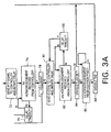
- the RFID tag remains in a normally powered off condition 50 until powered on 52 and initialized 54 in response to receipt of a high energy content transmission broadcast by the network controller to all the RFID tags.
- the RFID tag 10 receives the high energy content transmission from the network controller on receiver antenna 40, a voltage is accumulated across the terminals of energy storage capacitor 36. When the voltage exceeds a threshold value, a RESET signal is generated within the RFID tag to initialize 54 the digital circuitry of the integrated circuit (IC) 30 to predetermined states.
- IC integrated circuit
- the command code is comprised of several portions which convey various information to the RFID tag.
- a portion of the command code indicates to the RFID tag that the command originated from a POST.
- Another portion of the command code indicates whether article-identifying information is to be read from (READ mode) or written to the RFID tag (WRITE mode).
- Still another portion of the command code contains a type-identifier which is used by the individual RFID tag to determine whether it belongs to the group of tags which are addressed by the particular command.
- the portion of the command code which indicates the origin of the command (i.e. POST) is examined, 62, by circuitry within the particular RFID tag. If the command code is from a POST a disable flag is raised, 64, which sets the particular RFID tag to be permanently disabled at the conclusion of the communication with the POST. If the command is not from a POST, the RFID tag determines if the type-identifier contained in the command code matches, 60, the type-identifier stored in memory within the RFID tag. If the command is from a POST, or if the received type-identifier matches, 60, the stored type-identifier in a particular RFID tag, the communication sequence is allowed to proceed for that tag. If the command is not from a POST and the two type-identifiers do not match, the RFID tag is powered off again, 50,and remains in a powered off state until powered on again by receipt of a high energy content transmission as described above.
- each RFID tag has a random number generator 266 and a digital counter 264 responsive to a local clock signal 8KCLK, 228, within the RFID tag.
- Counter 264 is reset at the time of initialization.
- the random number generator 66 delivers a random number to be held for comparison, 70, with the output of the digital counter.
- the counter begins counting up, 68, towards the random number with the passage of successive time periods.
- RTT request to transmit signal
- the requesting RFID tag then waits, 74, for a first acknowledgment signal from the external network controller.
- a delay count is initiated from the time the request to transmit signal is transmitted by the RFID tag. If the first acknowledgment signal is received by the requesting RFID tag before the delay count reaches a value indicating that a predetermined time period has been exceeded, 76, i.e., before the delay counter "times out", then the requesting RFID tag determines next whether a collision has occurred, 78. If the first acknowledgment signal is not received by the requesting RFID tag within a predetermined time period after transmission of the request to transmit signal, the delay counter times out, 76, which indicates to the requesting RFID tag that the external network controller did not receive the RFID tag's request to transmit signal correctly.
- Receipt of the first acknowledgment signal by the RFID tag too early after transmission of the request to transmit signal indicates to the RFID tag that a collision has occurred, 78, in that the first acknowledgment signal had been an intended response to some other RFID tag which had sent a request to transmit signal.
- receipt of the first acknowledgment signal too early or too late with respect to when the request to transmit signal is sent causes the requesting RFID tag to generate, 66, a new random number, to reset and restart its counter 68, and to reinitiate the above-described communication sequence with the network controller.
- Receipt of the first acknowledgment signal by the RFID tag within the predetermined time period permits the RFID tag to perform the next step of the communication sequence, that of transmitting a data-containing signal: for example, transmitting, 80, the article ID code to the external network controller.
- the RFID tag After a particular RFID tag transmits, 80, its article ID code to the network controller, the RFID tag then waits for receipt, 82, of a second acknowledgment signal from the network controller which signifies that the ID code was received. A delay count is initiated in the particular RFID tag from the time that the article ID code is transmitted. If the second acknowledgment signal is received, 82, from the network controller before the delay count reaches a value indicating the passage of a predetermined time period and times out, 100, then the particular RFID tag concludes that its transmission of the ID code has been successful.
- the RFID tag then checks again to determine whether it is communicating with a POST type network controller, as is the case if the disable flag has been raised, 84, in the particular RFID tag. If the disable flag has not been raised, the RFID tag powers itself off, 50, to await the next command from the network controller. If the disable flag has been raised, the particular RFID tag then waits for receipt, 86, of a third acknowledgment signal from the POST which signifies that all RFID tags have been read successfully. Once the third acknowledgment is received from the POST the RFID tag disables itself permanently from further communication, 88.
- a particular RFID tag may receive communications from the network controller that were not intended for it. Should the first acknowledgment signal be received by a particular RFID tag before that tag has transmitted, 98, a request to transmit signal, but after the counter in the particular RFID tag has begun incrementing, then that RFID tag concludes that the first acknowledgment was intended for some other RFID tag which has been given permission to transmit. The counter of the particular RFID tag is therefore halted temporarily, 96, to permit the RFID tag having permission to transmit to complete transmission of its data-containing signal to the external network controller.
- the halted RFID tag Only after the second acknowledgment is sent by the external network controller and received, 94, by the halted RFID tag does the halted RFID tag resume incrementing, 68, its counter again. It will be appreciated that the first acknowledgment signal will generally cause all of the RFID tags to be temporarily halted except for the one which currently has been given permission to transmit.
- the delay count following the transmission of the data-containing signal by a particular RFID tag will time out, 100, indicating to the particular RFID tag that the network controller has not received the data-containing signal correctly from the particular RFID tag.
- the particular RFID tag resends, 80, the data- containing signal to the network controller and again waits for receipt of a second acknowledgment signal.
- the tags will revert to a powered off condition automatically within a predetermined time period after termination of the external RF transmissions.
- the predetermined time period is determined by the time for the voltage across the terminals of energy storage capacitor 36 to decay below the threshold required to keep the tag operating.
- the RFID tag is provided with an additional "watchdog timer" to power off the tag in case of communication malfunction. The watchdog timer located within the RFID tag (not shown) terminates the communication sequence for that tag and powers off the tag if no acknowledgments are received within a longer predetermined time period than the predetermined delay timeout periods which follow the first and second acknowledgments.
- a special type of network controller called an inventory terminal can be used to receive and record article-identifying information for the number and type of articles which are displayed or stored. All aspects of the communication sequence remain the same with the INVT as for the POST, except that network controller commands originating from the INVT, e.g. the BEGIN signal and acknowledgment signals, do not contain a bit which identifies the command as having come from a POST, such that a disable flag will be raised in the RFID tag.
- PROGRAMMER programmer terminal
- PROGRAMMER programmer terminal
- the initial command sent by the PROGRAMMER contains a bit which indicates to the RFID tag that WRITE mode is selected, 58.
- the initial command also contains article-identifying information, i.e. a type-identifier and a specific article ID code.
- Incoming command and acknowledgment signals, 234, which have been amplitude modulated with a binary signal code and transmitted as a wireless radio frequency (RF) signal by the network controller are received at the receiver 270.
- the receiver demodulates the incoming signal and passes a raw binary signal RxD, 272, to the decoder 274.
- the decoder recovers the received clock RxC, 220, associated with the signal and, as will be further described, regenerates the binary signal to prevent noise in the raw signal RxD, 272, from being passed to other elements within the RFID tag.
- the recovered clock signal RxC, 220 is used to transfer the regenerated binary signal SI, 210, into the shift register 244.
- Shift register 244 can be used to shift a serial binary signal, such as a request to transmit signal, RTT, or an article ID code, into encoder 236 serially to be amplitude modulated and transmitted as a wireless RF signal by the transmitter 238 to the external network controller 12.
- the shift register 244 can be used to output command code data 250 from the incoming signal on a parallel output interface (not pictured as a separate element) into a type comparator 282 which compares the type-identifier in the command code 254 with a type-identifier 256 retrieved from a programmable read only memory (“PROM”) 252 within the RFID tag.
- PROM programmable read only memory
- the parallel output interface of the shift register is also used to output individual signal lines or pairs HOLD, 246, and ACK [2,1], 248, to the control element 200.
- the control element 200 controls the sequence of operations and data flow within the RFID tag in response to the presence of internal signals within the RFID tag at a given point in time. These internal signals correspond to the RFID tag's logical "state.” It will be appreciated that the control element 200 can be constructed by a read only memory having as inputs the internal signals within the RFID tag and which address, in their various combinations, locations within the memory which contain outputs of the control element which correspond to the next "state" of the RFID tag.
- Random number RN, 268, is delivered by a random number generator 266 to a comparator 286 for comparison with the output of a digital counter 264.
- the RNMATCH output 310 of the comparator 286 is raised to signal the control element 200 to send the request to transmit signal.
- a timeout detector 289 uses the six lowest order bits [5..0] of the counter output 312 to determine when any of three particular delay counts: TIMEOUT 1, 304, TIMEOUT 2, 306, and CDET, 308,have been met or exceeded.
- the RFID tag also includes a multiplexer MUX, 260, used to channel a received clock signal RxC, 220, or a transmitted clock signal TxC, 218, to the shift register 244 as SCLK, 212, under the control of clock select signal CLKSEL, 222, for use in inputting or outputting a binary signal to the shift register from the decoder or encoder, respectively.
- the RFID tag runs on a CLOCK, 294, provided by a 1 Mhz local oscillator 292, the output of which is divided 16 times to form the clock inputs 3TC (204) and 16RC (276) to encoder 240 and decoder 274 respectively.
- the 3TC clock input is further divided eight times to form a clock signal running at 7.8125 kHz (“8KCLK”), 228, which is the clock signal used to increment the digital counter 264.
- 8KCLK 7.8125 kHz
- the decoder regenerates the raw binary signal RxD, 272, in the following manner.
- clock input 16RC 276) the incoming raw binary signal RxD, 272, is sampled at the rate of 16 times per data bit. The samples are recorded within the decoder as low or high voltage samples.
- An edge detector (not shown) within the decoder is used to recover the clock signal RxC, 278, from the raw binary signal RxD, 272.
- Clock signal RxC, 278, is further used to determine when recording of the voltage samples for the set of 16 samples for each data bit should begin. If the number of high voltage samples in each set of 16 exceeds the number of low voltage samples,then the incoming data bit is regenerated as a binary one.
- the incoming data bit is regenerated as a binary zero.
- the stream of regenerated binary ones and zeros are output from the decoder as SI, 210, which is the serial input to the shift register 244.
- Decoder input RMOD, 232 is a predetermined number which indicates the length of the incoming signal to be decoded. The value of RMOD may be programmed to permit decoding of signals of other lengths, but the programming must be done prior to the time of signal reception.
- the decoder determines that it has finished decoding the signal of the appropriate length, it signals RxRDY, 312, to the control element 200 to enable further processing to proceed.
- a typical communication begins as follows.
- the external network controller 12 such as a POST sends a high energy content transmission to the RFID tag 10.
- the RFID tag is powered on and initialized. Exceeding the threshold raises the RESET, 290, input to the control element 200, thereby causing the control element 200 to reset elements under its control, e.g. resetting the counter 264 by means of the CRST line, permitting the local oscillator 292 to begin running, and resetting all internal signal lines within the RFID tag.
- the RFID tag now waits for receipt of a 'BEGIN' command from the network controller.
- the receiver demodulates the incoming amplitude-modulated RF signal, and outputs a raw binary signal RxD, 272, to the decoder.
- the decoder 274 outputs a regenerated binary signal containing a command code as serial input SI, 210, to the shift register 244.
- the decoder 274 raises signal line RxRDY, 312, to the control element 200.
- Control element 200 then activates the shift register 244 to output the received command code over its parallel interface 250.
- a portion of the received command code is held as the received type-identifier input 254 to the type comparator 282.
- the received type-identifier is compared to a type-identifier stored in the RFID tags which has been retrieved into LATCH 258 for comparison by the following procedure.
- the control element Upon receipt of the RESET signal 290 by the control element 200 during initialization of the RFID tag, the control element has raised PROM chip select line /CS, 214, and retrieve line /RECALL, 215, to retrieve the type-identifier from its stored location in the PROM, 252.
- the retrieved type-identifier is stored into and held in a LATCH 258 by the signal TLATCH, 217, from the control element 200 until it is compared to the received type-identifier by the type comparator 282.
- the TMATCH line 300 is raised.
- the control element 200 is programmed to react to an active TMATCH line 300 by raising the CRST line 224 to reset and start the counter 264 and by raising the SET RN line 230 to cause the random number to be generated.
- the random number RN, 268, is delivered from the random number generator 266 to a latch (not shown) located within the comparator circuit 286. With each clock cycle, the comparator compares the 13 highest order bits [14..2] of the count 313, to determine if the count and the latched random number match. When the two match, the RNMATCH line 310 is raised to signal the control element 200 that the request to transmit (RTT) signal can be sent. In response thereto, the control element 200 signals the encoder 240 through TMOD 202 to output a generic, "hard-coded" RTT stored within the encoder to the transmitter 238 through the line TxD 237. This TxD signal,237, is then amplitude modulated onto an RF carrier by the transmitter 238 and transmitted on the transmitter antenna 38 (FIG. 2) as the output signal 280.
- a latch not shown
- the TDONE line 288 is raised to notify the control element 200 of the same. If the RTT signal that was transmitted results in the network controller granting permission to transmit to the requesting RFID tag, the next command to be received by the RFID tag will be a first acknowledgment.
- the first acknowledgment is received as a serial binary signal as described above for the BEGIN command.
- the ACK1 line, 248, of the shift register's parallel output interface becomes active.
- the control element 200 acts upon the ACK1, 248, input in accordance with the state of other inputs, RNMATCH, 310, and CDET, 308, to determine the appropriate action to take next.
- the control element 200 concludes that it has received the first acknowledgment signal at the correct time.
- the control element then raises /RECALL, 216, with the chip select lines /CS 214 to retrieve and output the article ID code from the PROM, 252, to the shift register 244 to be encoded and transmitted externally.
- the start-suspend counter line SS 226 is raised to stop the counter 264 from incrementing.
- start-suspend counter line SS 226 is lowered, thereby permitting the counter to resume incrementing.
- ACK1, 248, RNMATCH, 310 and CDET, 308, are all active at the same time, but TIMEOUT 1 is not, then the first acknowledgment has been received too early after the sending of the request to transmit, which indicates that a collision has occurred.
- CDET, 308, is held active from the time that the request to transmit or the article ID code is transmitted (as is indicated to the control element when the signal TDONE, 288, is raised) until sufficient time has elapsed to permit a response to the transmission, e.g. a first acknowledgment, to have been received.
- the delay count following the sending of the request to transmit signal is maintained and checked in the following manner. With every clock cycle, the timeout detector 284 tests the six lowest order bits [5..0] of the counter output 313 to determine the elapsed time. When the delay count following the sending of the request to transmit signal is exceeded, TIMEOUT 1, 304, is raised. If ACK1, 248, is not active by that time to indicate that the first acknowledgment has been received, the control element concludes that it has not been granted permission to transmit at that time.
- control element 200 In response to either CDET, 308, or TIMEOUT 1, 304, being raised, the control element 200 raises SET RN, 230, and raises CRST, 224, momentarily to signal the random number generator 266 to generate a new random number and to restart the counter 264, respectively, in order to begin the communication sequence again. Similarly, after the RFID tag transmits the data-containing signal, the control element 200 resets the counter 264 by raising CRST, 224.
- the next command to be received by the RFID tag will be a second acknowledgment signal from the network controller. Receipt of the second acknowledgment will be indicated as ACK2, 248, to the control element 200.
- the control element 200 determines if the disable flag has been raised 84 (Fig. 3). This disable flag is a bit stored in a bit-storing device, e.g. a latch or a "flip-flop" (not shown) located in the control element 200. The status of the disable flag is dependent on whether the command code sent by the network controller at the beginning of the communication session contains a bit that indicates that the network controller is a POST.
- the communication is terminated upon receipt of the second acknowledgment, and the RFID tag waits for the network controller to power it down, i.e. to discontinue sending the high energy content RF signal. If the disable flag has not been raised, thus indicating that the network controller is a POST, the RFID tag remains active until receipt of a third acknowledgment ACK3, 302.
- the RFID tag After sending the data-containing signal, the RFID tag again maintains and checks a delay count while waiting for receipt of a second acknowledgment signal. If the second acknowledgment signal has not been received before the delay count is exceeded, TIMEOUT 2, 306, is raised. The control element 200 then raises the RECALL, 216, and /CS, 214, inputs to the PROM 252 to begin transmitting the data-containing signal again to the network controller.
- the network controller sends a third acknowledgment which causes line ACK3 302 in the RFID tag to become active.
- the ACK3 signal, 302 causes the RFID tag to become disabled from further communication with the network controller.
- permanent disablement may be accomplished through a switch (not shown) located in the PROM 252 which is operable by the control element 200 upon receipt of ACK3, 302, to short circuit the terminals of energy storage capacitor 36 (Fig. 2).
- an effective disabling mechanism can be provided which is reversible at a later time by a PROGRAMMER type network controller.
- the RFID tag can be provided with a switch (not shown), again located in the PROM, 252, which is operable by the control element 200 upon receipt of ACK3, 302, to disable transmissions from the RFID tag, but which does not affect reception by the tag of incoming commands.
- Such a switch may be provided by a latch in the PROM 252 which, when in the 'disable' state, causes the control element 200 or to hold start-suspend counter line SS, 228, in the suspend state, or, hold encoder control inputs TMOD, 202, in a transmission-disabled condition.
- the PROGRAMMER network controller can then be used at a later time to "flip" the switch of the disabled tag, i.e. to reset the latch in the PROM 252 to the fully enabled state, to permit the RFID tag to transmit responses to the network controller again.
- the data terminal of the present invention can be put to many uses besides that of an RFID tag attached to articles for use in a supermarket checkout system.
- the uses to which the data terminal is adapted are: airwave or network data communications in general; telemetry; retail sales in general; delivery control; inventory control; automatic toll collection, speed checking or identification of vehicles on a highway; identification of and the locating of persons, animals, or component parts or stock items and the like which occupy, enter, or leave a defined area.
Landscapes
- Engineering & Computer Science (AREA)
- Physics & Mathematics (AREA)
- General Physics & Mathematics (AREA)
- Toxicology (AREA)
- Computer Vision & Pattern Recognition (AREA)
- Theoretical Computer Science (AREA)
- Health & Medical Sciences (AREA)
- Artificial Intelligence (AREA)
- Computer Networks & Wireless Communication (AREA)
- Electromagnetism (AREA)
- General Health & Medical Sciences (AREA)
- Mobile Radio Communication Systems (AREA)
- Near-Field Transmission Systems (AREA)
- Exchange Systems With Centralized Control (AREA)
- Communication Control (AREA)
- Radar Systems Or Details Thereof (AREA)
Claims (16)
- Verfahren zur Kommunikation zwischen einer Mehrzahl von Datentranspondern (10) und einem Netzwerkcontroller (12), umfassend die Schritte:(a) Initialisieren (54) jedes Datentransponders als Antwort auf den Empfang eines Signals, das von dem Netzwerkcontroller zu allen Datentranspondern übertragen wurde;(b) Erzeugen (66) einer Zufallszahl in jedem Datentransponder nach der Initialisierung;(c) Erhöhen (68) eines Zählers in jedem Datentransponder als Antwort auf das Verstreichen aufeinander folgender Zeitabstände;(d) Übertragen (72) eines "Request to transmit" -Signals von dem Datentransponder an den Netzwerkcontroller; und(e) Übertragen (80) eines Daten enthaltenden Signals an den Netzwerkcontroller, falls ein erstes Bestätigungssignal von dem Netzwerkcontroller empfangen worden ist, welches erste Bestätigungssignal den abfragenden Transponder nicht speziell identifiziert, gekennzeichnet durch den Schritt des Vergleichens (70) der Zufallszahl mit dem durch den Zähler ermittelten Zählwert während aufeinanderfolgender Zeiträume; derart, dass das "Request to transmit"-Signal übertragen wird, wenn die Zufallszahl in dem Datentransponder mit dem in dem Zähler ermittelten Zählwert übereinstimmt; und derart, dass das Daten enthaltende Signal nur übertragen wird, wenn das erste Bestätigungssignal von dem Netzwerkcontroller innerhalb eines festgelegten Zeitraums empfangen wird, nachdem der Datentransponder das "Request to transmit"-Signal überträgt.
- Verfahren nach Anspruch 1, dadurch gekennzeichnet, dass falls, das erste Bestätigungssignal von dem Netzwerkcontroller nicht innerhalb des festgelegten Zeitraums empfangen wird, nachdem der Datentransponder das "Request to transmit"-Signal überträgt, eine neue Zufallszahl erzeugt wird und das Verfahren gemäß Patentanspruch 1 beginnend bei dem Schritt (c) wiederholt wird.
- Verfahren nach Anspruch 2, ferner umfassend die folgenden Schritte:(a) zeitweises Aussetzen (96) des Betriebs des Zählers im Datentransponder, falls das erste Bestätigungssignal von dem Netzwerkcontroller empfangen wird, bevor der Datentransponder das "Request to transmit"-Signal überträgt; und(b) Wiederaufnehmen (68) des Betriebs des Zählers in dem Datentransponder, falls ein zweites Bestätigungssignal von dem Netzwerkcontroller innerhalb eines festgelegten Zeitraums nach dem Aussetzen des Betriebs erhalten wird.
- Verfahren nach Anspruch 3, ferner umfassend den Schritt des Wiederübertragens des Daten enthaltenden Signals, falls das zweite Bestätigungssignal nicht von dem Netzwerkcontroller innerhalb eines festgelegten Zeitraums empfangen worden ist, nachdem der Datentransponder das Daten enthaltende Signal überträgt, und Beenden der Kommunikation falls das zweite Bestätigungssignal innerhalb eines festgelegten Zeitraums empfangen worden ist.
- Verfahren nach Anspruch 4, ferner umfassend den Schritt des Beendens der Kommunikation, falls weder das erste Bestätigungssignal noch das zweite Bestätigungssignal von dem Netzwerkcontroller innerhalb eines festgelegten Zeitraums nach der Initialisierung des Datenterminals empfangen worden ist.
- Verfahren nach Anspruch 5, ferner umfassend den Schritt des Herunterfahrens (50) und permanenten Ausschaltens des Datentransponders, falls ein drittes Bestätigungssignal von dem Netzwerkcontroller empfangen worden ist, nachdem das zweite Bestätigungssignal empfangen worden ist.
- Verfahren nach einem der vorangehenden Ansprüche, wobei die Übertragung zwischen dem Datentransponder und dem Netzwerkcontroller seriell und drahtlos über eine Funkfrequenz erfolgt.
- Verfahren nach einem der vorangehenden Ansprüche, wobei der Datentransponder an einem Artikel (24) angepasst angebracht ist.
- Verfahren nach einem der vorangehenden Ansprüche, wobei das Daten enthaltende Signal einen Artikelidentifikationscode umfasst, der von einem Speichergerät (252) in dem Datentransponder ausgelesen wird.
- Datentransponder (10) zur Kommunikation mit einem Netzwerkcontroller (12), der Transponder umfasst:(a) einen Zufallszahlengenerator (266) der eine Zufallszahl erzeugt als Antwort auf ein von dem Netzwerkcontroller empfangenes Signal;(b) einen Zähler (264) der einen Zählwert erhöht (68) und beibehält als Antwort auf das Verstreichen aufeinander folgender Zeiträume; und(c) einen Übertrager (238) der ein "Request to transmit"-Signal an den Netzwerkcontroller überträgt (72) und welcher Übertrager ein Daten enthaltendes Signal an den Netzwerkcontroller überträgt als Antwort auf den Empfang eines ersten Bestätigungssignals, welches erste Bestätigungssignal den jeweiligen Datentransponder nicht speziell identifiziert nach dem Übertragen des "Request to transmit"-Signals, dieser Transponder ist gekennzeichnet durch einen Komparator (286) der die Zufallszahl mit dem von dem Zähler während aufeinander folgender Zeiträume beibehaltenen Zählwert vergleicht (70); derart, dass der Übertrager das "Request to transmit"-Signal überträgt, wenn die Zufallszahl in dem Datentransponder mit dem in dem Zähler gespeicherten Zählwert übereinstimmt, und wobei das Daten enthaltende Signal nur übertragen wird, falls das erste Bestätigungssignal von dem Netzwerkcontroller innerhalb eines festgelegten Zeitraums empfangen worden ist, nachdem der Datentransponder das "Request to transmit"-Signal überträgt.
- Datentransponder nach Anspruch 10, wobei der Zufallszahlengenerator eine neue Zufallszahl erzeugt, falls das erste Bestätigungssignal von dem Netzwerkcontroller nicht innerhalb des festgelegten Zeitraums nach der Übertragung des "Request to transmit"-Signals durch den Übertrager empfangen wird.
- System zur Kommunikation von Informationen, umfassend wenigstens einen Datentransponder nach Anspruch 10 und ein Terminal, das Terminal umfasst:einen Übertrager, der ein Anfangssignal an den wenigstens einen Datentransponder überträgt und welcher Transmitter ein erstes Bestätigungssignal als Antwort auf den Empfang eines "Request to transmit"-Signals von dem wenigstens einen Transponder überträgt; undeinen Empfänger, der ein Informationen enthaltendes Signal von dem wenigstens einen Transponder empfängt.
- System nach Anspruch 12, wobei der Übertrager in dem Terminal ein zweites Bestätigungssignal als Antwort auf den Empfang eines Informationen enthaltenden Signals von dem Datentransponder überträgt.
- System nach Anspruch 13, wobei der Transmitter in dem Terminal ein drittes Bestätigungssignal als Antwort auf den Empfang eines Informationen enthaltenden Signals von dem wenigstens einen Datentransponder überträgt, an den das Terminal das Anfangssignal übertragen hat.
- System nach einem der Ansprüche 12 bis 14, wobei der Übertrager in dem Terminal ein Informationen enthaltendes Signal überträgt, das in dem Datentransponder gespeichert werden soll.
- System nach einem der Ansprüche 12 bis 14, wobei der Übertrager in dem Terminal ein Informationen enthaltendes Signal überträgt, das von dem Datentransponder benutzt wird.
Applications Claiming Priority (2)
| Application Number | Priority Date | Filing Date | Title |
|---|---|---|---|
| US08/251,522 US5530702A (en) | 1994-05-31 | 1994-05-31 | System for storage and communication of information |
| US251522 | 1994-05-31 |
Publications (3)
| Publication Number | Publication Date |
|---|---|
| EP0689151A2 EP0689151A2 (de) | 1995-12-27 |
| EP0689151A3 EP0689151A3 (de) | 2000-01-19 |
| EP0689151B1 true EP0689151B1 (de) | 2003-08-27 |
Family
ID=22952328
Family Applications (1)
| Application Number | Title | Priority Date | Filing Date |
|---|---|---|---|
| EP95302630A Expired - Lifetime EP0689151B1 (de) | 1994-05-31 | 1995-04-20 | System zum Speichern und Übertragen von Information |
Country Status (5)
| Country | Link |
|---|---|
| US (1) | US5530702A (de) |
| EP (1) | EP0689151B1 (de) |
| AT (1) | ATE248406T1 (de) |
| CA (1) | CA2146276C (de) |
| DE (1) | DE69531569T2 (de) |
Cited By (4)
| Publication number | Priority date | Publication date | Assignee | Title |
|---|---|---|---|---|
| US6646554B1 (en) | 1998-06-08 | 2003-11-11 | 3M Innovative Properties Company | Identification tag with enhanced security |
| US6768419B2 (en) | 1998-08-14 | 2004-07-27 | 3M Innovative Properties Company | Applications for radio frequency identification systems |
| US7044373B1 (en) | 1998-08-14 | 2006-05-16 | 3M Innovative Properties Company | Radio frequency identification systems applications |
| WO2021133684A1 (en) * | 2019-12-28 | 2021-07-01 | Avery Dennison Retail Information Services, Llc | Shopping cart/basket reader systems and methods |
Families Citing this family (157)
| Publication number | Priority date | Publication date | Assignee | Title |
|---|---|---|---|---|
| DE19503209C1 (de) * | 1995-02-02 | 1996-10-02 | Becker Gmbh | Verfahren zur Initialisierung eines Netzwerkes mit mehreren masterfähigen also taktgebefähigen Netzteilnehmern |
| US6329139B1 (en) | 1995-04-25 | 2001-12-11 | Discovery Partners International | Automated sorting system for matrices with memory |
| TW383527B (en) * | 1995-11-09 | 2000-03-01 | British Tech Group | Enhanced detectionn of multipled data transmissions |
| JP3494800B2 (ja) * | 1996-04-15 | 2004-02-09 | 和夫 坪内 | 無線icカードシステム |
| US6130602A (en) * | 1996-05-13 | 2000-10-10 | Micron Technology, Inc. | Radio frequency data communications device |
| US6362737B1 (en) * | 1998-06-02 | 2002-03-26 | Rf Code, Inc. | Object Identification system with adaptive transceivers and methods of operation |
| AU4622897A (en) | 1996-09-13 | 1998-04-02 | Temic Telefunken Microelectronik Gmbh | Data transfer method for a scanning identification system |
| DE19646153A1 (de) * | 1996-11-08 | 1998-05-14 | Siemens Nixdorf Inf Syst | Warenkorbabtaster |
| ZA9710865B (en) * | 1996-12-04 | 1998-06-23 | Frederic Pagnol | A method of monitoring and programming a plurality of transponders simultaneously, and apparatus for implementing the method. |
| FR2758027B1 (fr) * | 1996-12-27 | 1999-01-29 | Gemplus Card Int | Systeme de communication par interrogation a distance permettant la transmission de commandes d'inhibition |
| EP0910899B1 (de) * | 1997-01-21 | 2005-04-20 | Koninklijke Philips Electronics N.V. | Transponderkommunikationseinrichtung |
| US5883582A (en) * | 1997-02-07 | 1999-03-16 | Checkpoint Systems, Inc. | Anticollision protocol for reading multiple RFID tags |
| US6208235B1 (en) | 1997-03-24 | 2001-03-27 | Checkpoint Systems, Inc. | Apparatus for magnetically decoupling an RFID tag |
| GB2325141A (en) | 1997-05-14 | 1998-11-18 | British Tech Group | Automatic milking system |
| JP4172727B2 (ja) * | 1997-05-14 | 2008-10-29 | ズィーアイエイチ・コーポレーション | 識別システムの改良 |
| US6077106A (en) * | 1997-06-05 | 2000-06-20 | Micron Communications, Inc. | Thin profile battery mounting contact for printed circuit boards |
| US5942977A (en) | 1997-08-13 | 1999-08-24 | Ludwig Kipp | Radio transponder |
| US5986570A (en) * | 1997-09-03 | 1999-11-16 | Micron Communications, Inc. | Method for resolving signal collisions between multiple RFID transponders in a field |
| US6118789A (en) | 1998-02-19 | 2000-09-12 | Micron Technology, Inc. | Method of addressing messages and communications system |
| GB9724183D0 (en) * | 1997-11-14 | 1998-01-14 | British Tech Group | Identification system |
| US7035818B1 (en) * | 1997-11-21 | 2006-04-25 | Symbol Technologies, Inc. | System and method for electronic inventory |
| US7844505B1 (en) | 1997-11-21 | 2010-11-30 | Symbol Technologies, Inc. | Automated real-time distributed tag reader network |
| US6072801A (en) | 1998-02-19 | 2000-06-06 | Micron Technology, Inc. | Method of addressing messages, method of establishing wireless communications, and communications system |
| US6275476B1 (en) | 1998-02-19 | 2001-08-14 | Micron Technology, Inc. | Method of addressing messages and communications system |
| USRE43382E1 (en) | 1998-02-19 | 2012-05-15 | Round Rock Research, Llc | Method of addressing messages and communications systems |
| US6061344A (en) | 1998-02-19 | 2000-05-09 | Micron Technology, Inc. | Method of addressing messages and communications system |
| GB9804584D0 (en) * | 1998-03-04 | 1998-04-29 | Trolley Scan Pty Limited | Identification of objects by a reader |
| GB2335573B (en) * | 1998-03-18 | 2000-03-15 | Univ Singapore | An RF transponder identification system and protocol |
| US5955951A (en) * | 1998-04-24 | 1999-09-21 | Sensormatic Electronics Corporation | Combined article surveillance and product identification system |
| US6232585B1 (en) * | 1998-05-19 | 2001-05-15 | Thermal Solutions, Inc. | Temperature self-regulating food delivery system |
| CN100459443C (zh) * | 1998-06-25 | 2009-02-04 | 格姆普拉斯公司 | 可传送禁止命令的近距离询问通信方法 |
| JP2000013337A (ja) * | 1998-06-26 | 2000-01-14 | Nippon Columbia Co Ltd | データ多重放送方法、データ多重化放送システム、受信装置、録音装置 |
| US6252886B1 (en) | 1998-07-06 | 2001-06-26 | Sony Corporation | Bandwidth reservation |
| AU4974499A (en) * | 1998-07-06 | 2000-01-24 | Sony Corporation | Bandwidth reservation |
| CA2277194A1 (en) * | 1998-08-12 | 2000-02-12 | Robert W. Spurr | A printer media supply spool adapted to allow the printer to sense type of media, and method of assembling same |
| DE19837488A1 (de) * | 1998-08-12 | 2000-02-17 | Mannesmann Ag | Abbuchungsgerät zur Abrechnung von Nutzungsgebühren |
| US6424262B2 (en) | 1998-08-14 | 2002-07-23 | 3M Innovative Properties Company | Applications for radio frequency identification systems |
| AU762495B2 (en) | 1998-08-14 | 2003-06-26 | 3M Innovative Properties Company | Application for a radio frequency identification system |
| US6480143B1 (en) * | 1998-11-09 | 2002-11-12 | Supersensor (Proprietary) Limited | Electronic identification system |
| US6535109B1 (en) * | 1998-12-01 | 2003-03-18 | Texas Instruments Sensors And Controls, Inc. | System and method for communicating with multiple transponders |
| US7209891B1 (en) * | 1999-02-08 | 2007-04-24 | Ncr Corporation | Method and apparatus for operating a configurable remote supervisor terminal of a self-service retail checkout system |
| US6127938A (en) * | 1999-02-12 | 2000-10-03 | Privacy Shield L.L.C. | Adjustable shield for vehicle mounted toll collection identifier |
| US6400272B1 (en) | 1999-04-01 | 2002-06-04 | Presto Technologies, Inc. | Wireless transceiver for communicating with tags |
| WO2000077704A2 (en) * | 1999-06-11 | 2000-12-21 | Creative Golf Designs, Inc. | Inventory control system |
| EP1734461A2 (de) * | 1999-07-12 | 2006-12-20 | Matsushita Electric Industrial Co., Ltd. | Mobile Körperunterscheidungsvorrichtung zur raschen Erfassung entsprechender von Transpondern innerhalb eines Kommunikationsbereiches eines Interrogatorgeräts über Modulation von reflektierten Funkwellen übertragener Datensätze |
| US6320169B1 (en) * | 1999-09-07 | 2001-11-20 | Thermal Solutions, Inc. | Method and apparatus for magnetic induction heating using radio frequency identification of object to be heated |
| US6297734B1 (en) | 1999-09-23 | 2001-10-02 | Northrop Grumman Corporation | Randomization of transmit time |
| US6294997B1 (en) * | 1999-10-04 | 2001-09-25 | Intermec Ip Corp. | RFID tag having timing and environment modules |
| US6768749B1 (en) * | 1999-10-14 | 2004-07-27 | Cisco Technology, Inc. | Dual-channel communications protocol providing enhanced capabilities for modems |
| US6963270B1 (en) | 1999-10-27 | 2005-11-08 | Checkpoint Systems, Inc. | Anticollision protocol with fast read request and additional schemes for reading multiple transponders in an RFID system |
| US6943678B2 (en) * | 2000-01-24 | 2005-09-13 | Nextreme, L.L.C. | Thermoformed apparatus having a communications device |
| US6433313B1 (en) | 2000-02-15 | 2002-08-13 | Vesture Corporation | Apparatus and method for heated food delivery |
| US6384387B1 (en) | 2000-02-15 | 2002-05-07 | Vesture Corporation | Apparatus and method for heated food delivery |
| US6785739B1 (en) | 2000-02-23 | 2004-08-31 | Eastman Kodak Company | Data storage and retrieval playback apparatus for a still image receiver |
| US6603400B1 (en) | 2000-05-04 | 2003-08-05 | Telxon Corporation | Paper capacitor |
| US7019664B2 (en) | 2000-06-12 | 2006-03-28 | Supersensor (Proprietary) Limited | Reading protocol for transponders of electronic identification system |
| US20020183882A1 (en) | 2000-10-20 | 2002-12-05 | Michael Dearing | RF point of sale and delivery method and system using communication with remote computer and having features to read a large number of RF tags |
| AU2002211769B2 (en) | 2000-10-20 | 2006-10-26 | Promega Corporation | Radio frequency identification method and system of distributing products |
| USRE47599E1 (en) | 2000-10-20 | 2019-09-10 | Promega Corporation | RF point of sale and delivery method and system using communication with remote computer and having features to read a large number of RF tags |
| GB0028093D0 (en) * | 2000-11-17 | 2001-01-03 | Ratcliffe Anthony B | Electrical power control system |
| US7253717B2 (en) * | 2000-11-29 | 2007-08-07 | Mobile Technics Llc | Method and system for communicating with and tracking RFID transponders |
| US8315563B2 (en) * | 2000-12-22 | 2012-11-20 | Google Inc. | Wireless reader tags (WRTs) with sensor components in asset monitoring and tracking systems |
| US20040069851A1 (en) * | 2001-03-13 | 2004-04-15 | Grunes Mitchell B. | Radio frequency identification reader with removable media |
| JP3767405B2 (ja) * | 2001-04-09 | 2006-04-19 | ソニー株式会社 | 記録媒体制御方法、記録媒体対応装置 |
| DE60221446T2 (de) | 2001-05-14 | 2008-04-17 | Innovision Research & Technology Plc, Cirencester | Tragbares Kommunikationssystem zum Gebrauch in einem Verkaufssystem |
| US7377445B1 (en) | 2001-05-31 | 2008-05-27 | Alien Technology Corporation | Integrated circuits with persistent data storage |
| US6942155B1 (en) * | 2001-05-31 | 2005-09-13 | Alien Technology Corporation | Integrated circuits with persistent data storage |
| US7588185B2 (en) | 2001-06-07 | 2009-09-15 | 3M Innovative Properties Company | RFID data collection and use |
| FR2840472A1 (fr) * | 2002-06-04 | 2003-12-05 | St Microelectronics Sa | Procede anticollision pour module electronique sans contact |
| US20040049733A1 (en) * | 2002-09-09 | 2004-03-11 | Eastman Kodak Company | Virtual annotation of a recording on an archival media |
| US7233498B2 (en) | 2002-09-27 | 2007-06-19 | Eastman Kodak Company | Medium having data storage and communication capabilities and method for forming same |
| US20040066752A1 (en) * | 2002-10-02 | 2004-04-08 | Hughes Michael A. | Radio frequency indentification device communications systems, wireless communication devices, wireless communication systems, backscatter communication methods, radio frequency identification device communication methods and a radio frequency identification device |
| US6995655B2 (en) * | 2002-10-02 | 2006-02-07 | Battelle Memorial Institute | Method of simultaneously reading multiple radio frequency tags, RF tags, and RF reader |
| US7009526B2 (en) * | 2002-10-02 | 2006-03-07 | Battelle Memorial Institute | RFID system and method including tag ID compression |
| US7009495B2 (en) * | 2002-10-02 | 2006-03-07 | Battelle Memorial Institute | System and method to identify multiple RFID tags |
| US6914528B2 (en) | 2002-10-02 | 2005-07-05 | Battelle Memorial Institute | Wireless communication systems, radio frequency identification devices, methods of enhancing a communications range of a radio frequency identification device, and wireless communication methods |
| US7019617B2 (en) * | 2002-10-02 | 2006-03-28 | Battelle Memorial Institute | Radio frequency identification devices, backscatter communication device wake-up methods, communication device wake-up methods and a radio frequency identification device wake-up method |
| US7760835B2 (en) | 2002-10-02 | 2010-07-20 | Battelle Memorial Institute | Wireless communications devices, methods of processing a wireless communication signal, wireless communication synchronization methods and a radio frequency identification device communication method |
| US7019618B2 (en) | 2002-10-02 | 2006-03-28 | Battelle Memorial Institute | Wireless communications systems, radio frequency identification devices, wireless communications methods, and radio frequency identification device communications methods |
| US6842106B2 (en) | 2002-10-04 | 2005-01-11 | Battelle Memorial Institute | Challenged-based tag authentication model |
| JP2004152004A (ja) * | 2002-10-30 | 2004-05-27 | Canon Inc | 画像処理装置 |
| JP4208557B2 (ja) * | 2002-11-28 | 2009-01-14 | キヤノン株式会社 | 非接触通信方式カード |
| US6953919B2 (en) * | 2003-01-30 | 2005-10-11 | Thermal Solutions, Inc. | RFID-controlled smart range and method of cooking and heating |
| US8127984B2 (en) | 2003-06-13 | 2012-03-06 | Varia Holdings Llc | Emulated radio frequency identification |
| DE10328906A1 (de) * | 2003-06-26 | 2005-01-13 | Endress + Hauser Process Solutions Ag | Feldbusverteilereinheit |
| JP3553926B1 (ja) * | 2003-07-04 | 2004-08-11 | 株式会社メディアグラム | 通信システム |
| US7672872B2 (en) * | 2003-08-22 | 2010-03-02 | Smurfit-Stone Container Enterprises, Inc. | Point-of-purchase display with RFID inventory control |
| US7775432B2 (en) | 2003-10-16 | 2010-08-17 | Nokia Corporation | Terminal, method and computer program product for interacting with a signaling tag |
| US20050099303A1 (en) * | 2003-11-11 | 2005-05-12 | Zuckerman Andrew M. | Injection molded garment hanger |
| US7109986B2 (en) * | 2003-11-19 | 2006-09-19 | Eastman Kodak Company | Illumination apparatus |
| US7145464B2 (en) * | 2003-11-19 | 2006-12-05 | Eastman Kodak Company | Data collection device |
| US7009494B2 (en) * | 2003-11-21 | 2006-03-07 | Eastman Kodak Company | Media holder having communication capabilities |
| DE602004027532D1 (de) * | 2003-12-09 | 2010-07-15 | Intelleflex Corp | Batterieaktivierungsschaltung |
| FR2863745B1 (fr) * | 2003-12-16 | 2006-06-30 | St Microelectronics Sa | Memoire pour etiquettes rfid adaptee pour recevoir une commande de desactivation |
| JP4282534B2 (ja) * | 2004-04-22 | 2009-06-24 | 三菱電機株式会社 | Dsrc通信システムの車載端末 |
| US7573005B2 (en) * | 2004-04-22 | 2009-08-11 | Thermal Solutions, Inc. | Boil detection method and computer program |
| US7948381B2 (en) | 2004-04-30 | 2011-05-24 | Binforma Group Limited Liability Company | Reversibly deactivating a radio frequency identification data tag |
| US7098794B2 (en) * | 2004-04-30 | 2006-08-29 | Kimberly-Clark Worldwide, Inc. | Deactivating a data tag for user privacy or tamper-evident packaging |
| US7336183B2 (en) * | 2004-04-30 | 2008-02-26 | Kimberly-Clark Worldwide, Inc. | Decommissioning an electronic data tag |
| DE102004035062A1 (de) * | 2004-07-20 | 2006-02-16 | Infineon Technologies Ag | Identifikations-Datenträger, Lese-Vorrichtung und Identifikations-System |
| US8035482B2 (en) * | 2004-09-07 | 2011-10-11 | Eastman Kodak Company | System for updating a content bearing medium |
| US7362212B2 (en) * | 2004-09-24 | 2008-04-22 | Battelle Memorial Institute | Communication methods, systems, apparatus, and devices involving RF tag registration |
| US7650388B2 (en) * | 2005-01-13 | 2010-01-19 | Xerox Corporation | Wireless identification protocol with confirmation of successful transmission |
| US20060170556A1 (en) * | 2005-01-18 | 2006-08-03 | Lexin Technology Inc. | System for detecting an RFID tag |
| US20060208893A1 (en) * | 2005-02-28 | 2006-09-21 | Anson Gary S | Weight audit methods and systems utilizing data reader |
| US7728713B2 (en) | 2005-05-06 | 2010-06-01 | Intelleflex Corporation | Accurate persistent nodes |
| US7604178B2 (en) * | 2005-05-11 | 2009-10-20 | Intelleflex Corporation | Smart tag activation |
| US8248211B2 (en) | 2005-07-20 | 2012-08-21 | Intelleflex Corporation | Selective RF device activation |
| KR100651744B1 (ko) * | 2005-11-10 | 2006-12-01 | 한국전자통신연구원 | 다중 무선주파수 식별자 단일화 장치 및 그 방법 |
| US8548098B2 (en) * | 2005-12-15 | 2013-10-01 | Intelleflex Corporation | Clock-free activation circuit |
| JP4548671B2 (ja) * | 2006-02-10 | 2010-09-22 | 富士通株式会社 | 質問器、応答器、応答器認証方法 |
| US7821400B2 (en) * | 2006-09-29 | 2010-10-26 | Datalogic Scanning, Inc. | System and method for verifying number of wireless tagged items in a transaction |
| US20080157925A1 (en) * | 2007-01-03 | 2008-07-03 | Intelleflex Corporation | Long range rfid device used with display, and systems and methods implementing same |
| US10817679B2 (en) * | 2007-01-26 | 2020-10-27 | Allen Hollister | Multidimensional sieving for high density low collision RFID tag fields |
| US7973644B2 (en) | 2007-01-30 | 2011-07-05 | Round Rock Research, Llc | Systems and methods for RFID tag arbitration where RFID tags generate multiple random numbers for different arbitration sessions |
| US7710275B2 (en) | 2007-03-16 | 2010-05-04 | Promega Corporation | RFID reader enclosure and man-o-war RFID reader system |
| US20080285622A1 (en) * | 2007-05-18 | 2008-11-20 | Cooktek, Llc | Detachable Tag-Based Temperature Sensor For Use In Heating Of Food And Cookware |
| US8134452B2 (en) * | 2007-05-30 | 2012-03-13 | Round Rock Research, Llc | Methods and systems of receiving data payload of RFID tags |
| US8130079B2 (en) | 2007-08-15 | 2012-03-06 | At&T Intellectual Property I, L.P. | Methods, systems, and products for discovering electronic devices |
| US7997486B2 (en) * | 2007-08-24 | 2011-08-16 | Wal-Mart Stores, Inc. | System, method, and apparatus of RFID point of sale |
| US8083140B1 (en) * | 2008-02-05 | 2011-12-27 | Sprint Communications Company L.P. | System and method of over-the-air provisioning |
| US8063740B1 (en) * | 2008-02-20 | 2011-11-22 | Impinj, Inc. | Interfacing to RFID reader utility that causes RFID tags to reply using changed reply timing |
| US8079132B2 (en) * | 2008-03-11 | 2011-12-20 | Henry Clayman | Method for shielding RFID tagged discarded items in retail, manufacturing and wholesale industries |
| US8143997B2 (en) * | 2008-06-30 | 2012-03-27 | International Business Machines Corporation | System for self-service checkout inventory control |
| US8427282B2 (en) | 2008-07-15 | 2013-04-23 | Zih Corp. | Identification system |
| US8706588B1 (en) | 2008-10-20 | 2014-04-22 | Sprint Communications Company L.P. | System and method of provisioning confidential information via a mobile device |
| US8060449B1 (en) | 2009-01-05 | 2011-11-15 | Sprint Communications Company L.P. | Partially delegated over-the-air provisioning of a secure element |
| US8705523B2 (en) | 2009-02-05 | 2014-04-22 | Google Inc. | Conjoined class-based networking |
| US8768845B1 (en) | 2009-02-16 | 2014-07-01 | Sprint Communications Company L.P. | Electronic wallet removal from mobile electronic devices |
| US9081996B2 (en) * | 2009-05-21 | 2015-07-14 | Alcatel Lucent | Identifying RFID categories |
| DE102010023051A1 (de) * | 2010-06-08 | 2011-12-08 | Achterberg Gmbh | Inventarisierungssystem auf der Basis eines RFID-Systems |
| US8462734B2 (en) | 2010-10-20 | 2013-06-11 | Nokia Corporation | Wireless docking with out-of-band initiation |
| US8554970B2 (en) | 2011-04-18 | 2013-10-08 | Nokia Corporation | Method, apparatus and computer program product for creating a wireless docking group |
| US8965286B2 (en) | 2011-05-13 | 2015-02-24 | Nokia Corporation | Inquiry response event control |
| US8929816B2 (en) | 2011-05-13 | 2015-01-06 | Nokia Corporation | Multiple apparatus selection via touch |
| US8965285B2 (en) | 2011-05-13 | 2015-02-24 | Nokia Corporation | Touch inquiry |
| US8929817B2 (en) | 2011-05-13 | 2015-01-06 | Nokia Corporation | Sensor-based touch inquiry control |
| US9288228B2 (en) | 2011-08-05 | 2016-03-15 | Nokia Technologies Oy | Method, apparatus, and computer program product for connection setup in device-to-device communication |
| US9158945B2 (en) * | 2013-04-18 | 2015-10-13 | Symbol Technologies, Llc | Defining a radio frequency identification read area |
| US9112790B2 (en) | 2013-06-25 | 2015-08-18 | Google Inc. | Fabric network |
| US9497787B2 (en) | 2013-11-25 | 2016-11-15 | Nokia Technologies Oy | Method, apparatus, and computer program product for managing concurrent connections between wireless dockee devices in a wireless docking environment |
| JP6276637B2 (ja) * | 2014-04-18 | 2018-02-07 | 東芝テック株式会社 | 読取装置及び商品販売データ処理装置 |
| JP6254895B2 (ja) * | 2014-04-18 | 2017-12-27 | 東芝テック株式会社 | 読取装置及び商品販売データ処理装置 |
| US9860297B2 (en) | 2014-06-02 | 2018-01-02 | Nokia Technologies Oy | Method, apparatus, and computer program product for media selection for moving user |
| US9635690B2 (en) | 2014-06-24 | 2017-04-25 | Nokia Technologies Oy | Method, apparatus, and computer program product for improving security for wireless communication |
| JP6276654B2 (ja) * | 2014-06-27 | 2018-02-07 | 東芝テック株式会社 | 読取装置及びプログラム |
| US9338635B2 (en) | 2014-07-01 | 2016-05-10 | Nokia Technologies Oy | Method, apparatus, and computer program product for device tracking |
| US9265080B1 (en) | 2014-10-01 | 2016-02-16 | Nokia Technologies Oy | Method, apparatus, and computer program product for multi-device output mode configuration |
| JP6200442B2 (ja) * | 2015-03-02 | 2017-09-20 | 東芝テック株式会社 | 読取装置及びpos装置 |
| JP2018132988A (ja) * | 2017-02-16 | 2018-08-23 | 東芝テック株式会社 | 読取装置 |
| WO2018213521A1 (en) | 2017-05-19 | 2018-11-22 | Walmart Apollo, Llc | Rfid error detection systems and methods |
| JP2019031361A (ja) * | 2017-08-07 | 2019-02-28 | 東芝テック株式会社 | 物品読取装置及び物品情報処理装置 |
| JPWO2019049953A1 (ja) * | 2017-09-07 | 2020-11-26 | パナソニックIpマネジメント株式会社 | 買物支援システム及び買物支援方法 |
| JP7214398B2 (ja) * | 2017-12-14 | 2023-01-30 | 東芝テック株式会社 | 読取装置 |
| JP7019441B2 (ja) * | 2018-02-07 | 2022-02-15 | 東芝テック株式会社 | 読取装置 |
| WO2021202847A1 (en) * | 2020-04-01 | 2021-10-07 | Nec Laboratories America, Inc. | Rfid-based self-checkout systems using cycle counting |
| US12337551B2 (en) | 2020-10-28 | 2025-06-24 | The Boeing Company | Automated fiber placement roller |
Family Cites Families (56)
| Publication number | Priority date | Publication date | Assignee | Title |
|---|---|---|---|---|
| US3819012A (en) * | 1970-03-20 | 1974-06-25 | Rca Corp | Merchandise handling and identifying system |
| US3804982A (en) * | 1972-08-10 | 1974-04-16 | Texas Instruments Inc | Data communication system for serially transferring data between a first and a second location |
| US3914762A (en) * | 1973-12-27 | 1975-10-21 | Rca Corp | Electronic identification system |
| GB2063011B (en) * | 1979-11-09 | 1983-10-12 | Philips Electronic Associated | Information transmission system |
| US4339753A (en) * | 1979-12-19 | 1982-07-13 | Rca Corporation | Vehicle identification system |
| US4814979A (en) * | 1981-04-01 | 1989-03-21 | Teradata Corporation | Network to transmit prioritized subtask pockets to dedicated processors |
| US4409592A (en) * | 1981-04-20 | 1983-10-11 | Hunt V Bruce | Multipoint packet data communication system using random access and collision detection techniques |
| US4519029A (en) * | 1981-05-18 | 1985-05-21 | Texas Instruments Incorporated | Data communications system with automatic communications mode |
| US4941123A (en) * | 1981-05-18 | 1990-07-10 | Texas Instruments Incorporated | Data communications system with automatic communications mode |
| US4535401A (en) * | 1982-06-30 | 1985-08-13 | Texas Instruments Incorporated | Apparatus and method for providing power from master controller to subcontrollers and data communication therebetween |
| US4546241A (en) * | 1982-12-10 | 1985-10-08 | Walton Charles A | Electronic proximity identification system |
| US4543654A (en) * | 1983-02-03 | 1985-09-24 | Wang Laboratories, Inc. | Interfacing a communication network |
| US4677614A (en) * | 1983-02-15 | 1987-06-30 | Emc Controls, Inc. | Data communication system and method and communication controller and method therefor, having a data/clock synchronizer and method |
| US4538262A (en) * | 1983-08-03 | 1985-08-27 | Rca Corporation | Multiplex bus system for controlling the transmission of data between a master control unit and a plurality of remotely located receiver-transmitter units |
| US4646090A (en) * | 1983-08-12 | 1987-02-24 | Rca Corporation | Codeable identifying tag and method of identification thereof |
| US4593281A (en) * | 1983-10-13 | 1986-06-03 | Rockwell International Corporation | Local area network interframe delay controller |
| US4590467A (en) * | 1983-10-13 | 1986-05-20 | Rockwell International Corporation | Local area network interface controller |
| US4554446A (en) * | 1983-11-18 | 1985-11-19 | Murphy Arthur J | Supermarket inventory control system and method |
| US4862160A (en) * | 1983-12-29 | 1989-08-29 | Revlon, Inc. | Item identification tag for rapid inventory data acquisition system |
| US4777591A (en) * | 1984-01-03 | 1988-10-11 | Texas Instruments Incorporated | Microprocessor with integrated CPU, RAM, timer, and bus arbiter for data communications systems |
| JPS60171475A (ja) * | 1984-02-15 | 1985-09-04 | アイデンティフィケ−ション・デバイセス・インコ−ポレ−テッド | 識別システム |
| GB8408538D0 (en) * | 1984-04-03 | 1984-05-16 | Senelco Ltd | Transmitter-responder systems |
| US4792018A (en) * | 1984-07-09 | 1988-12-20 | Checkrobot Inc. | System for security processing of retailed articles |
| US4644348A (en) * | 1984-11-13 | 1987-02-17 | Itt Corporation | Apparatus for providing masterless collision detection |
| US4647931A (en) * | 1984-11-29 | 1987-03-03 | Rca Corporation | Dual frequency identification system |
| US4872014A (en) * | 1985-01-31 | 1989-10-03 | General Electric Company | Object identification system and method utilizing radiometry |
| US4646295A (en) * | 1985-02-04 | 1987-02-24 | Rca Corporation | Frequency-division multiplex communications system having grouped transmitters and receivers |
| US4644561A (en) * | 1985-03-20 | 1987-02-17 | International Mobile Machines Corp. | Modem for RF subscriber telephone system |
| US4675863A (en) * | 1985-03-20 | 1987-06-23 | International Mobile Machines Corp. | Subscriber RF telephone system for providing multiple speech and/or data signals simultaneously over either a single or a plurality of RF channels |
| US5005125A (en) * | 1986-02-28 | 1991-04-02 | Sensormatic Electronics Corporation | Surveillance, pricing and inventory system |
| US5211129A (en) * | 1986-02-25 | 1993-05-18 | Destron/Idi, Inc. | Syringe-implantable identification transponder |
| US4926415A (en) * | 1987-02-04 | 1990-05-15 | Kabushiki Kaisha Toshiba | Local area network system for efficiently transferring messages of different sizes |
| EP0285419B1 (de) * | 1987-03-31 | 1994-08-24 | Identec Limited | Zugangskontrolleinrichtung |
| ATE98025T1 (de) * | 1987-07-31 | 1993-12-15 | Texas Instruments Deutschland | Transponder-anordnung. |
| US5018138A (en) * | 1987-11-10 | 1991-05-21 | Echelon Systems Corporation | Protocol for network having a plurality of intelligent cells |
| US4964053A (en) * | 1988-04-22 | 1990-10-16 | Checkrobot, Inc. | Self-checkout of produce items |
| US5121103A (en) * | 1988-07-29 | 1992-06-09 | Knogo Corporation | Load isolated article surveillance system and antenna assembly |
| US5012469A (en) * | 1988-07-29 | 1991-04-30 | Karamvir Sardana | Adaptive hybrid multiple access protocols |
| NL8802481A (nl) * | 1988-10-10 | 1990-05-01 | Texas Instruments Holland | Transponder alsmede werkwijze voor het vervaardigen daarvan. |
| NL8901659A (nl) * | 1989-06-30 | 1991-01-16 | Nedap Nv | Multipassysteem. |
| EP0409016A3 (en) * | 1989-07-10 | 1992-07-01 | Csir | System and method for locating labelled objects |
| DE4002801C1 (de) * | 1990-01-31 | 1991-04-11 | Texas Instruments Deutschland Gmbh, 8050 Freising, De | |
| US5083113A (en) * | 1990-01-31 | 1992-01-21 | Texas Instruments Incorporated | Inductive coupled object identification system and method |
| US5287113A (en) * | 1990-02-12 | 1994-02-15 | Texas Instruments Deutschland Gmbh | Voltage limiting batteryless transponder circuit |
| DK0467036T3 (da) * | 1990-06-15 | 1996-03-11 | Savi Techn Inc | Fremgangsmåde og apparatur til radioidentifikation og sporing |
| US5151895A (en) * | 1990-06-29 | 1992-09-29 | Digital Equipment Corporation | Terminal server architecture |
| NL9002191A (nl) * | 1990-10-09 | 1992-05-06 | Texas Instruments Holland | Transponder alsmede werkwijze voor het vervaardigen daarvan. |
| US5319641A (en) * | 1990-12-03 | 1994-06-07 | Echelon Systems Corp. | Multiaccess carrier sensing network communication protocol with priority messages |
| JP3100716B2 (ja) * | 1991-01-04 | 2000-10-23 | シーエスアイアール | 識別装置 |
| NL9100110A (nl) * | 1991-01-23 | 1992-08-17 | Texas Instruments Holland | Ondervraagstation voor identificatiedoeleinden met afzonderlijke zend- en ontvangantennes. |
| US5151684A (en) * | 1991-04-12 | 1992-09-29 | Johnsen Edward L | Electronic inventory label and security apparatus |
| US5239167A (en) * | 1991-04-30 | 1993-08-24 | Ludwig Kipp | Checkout system |
| US5218189A (en) * | 1991-09-09 | 1993-06-08 | Checkpoint Systems, Inc. | Binary encoded multiple frequency rf indentification tag |
| US5270717A (en) * | 1992-03-26 | 1993-12-14 | Texas Instruments Deutschland Gmbh | Extended range RF-ID transponder |
| US5227803A (en) * | 1992-07-22 | 1993-07-13 | Hughes Aircraft Company | Transponder location and tracking system and method |
| EP0604777A1 (de) * | 1992-12-28 | 1994-07-06 | Motorola, Inc. | Datenübertragungssystem und -verfahren |
-
1994
- 1994-05-31 US US08/251,522 patent/US5530702A/en not_active Expired - Lifetime
-
1995
- 1995-04-04 CA CA002146276A patent/CA2146276C/en not_active Expired - Fee Related
- 1995-04-20 DE DE69531569T patent/DE69531569T2/de not_active Expired - Lifetime
- 1995-04-20 EP EP95302630A patent/EP0689151B1/de not_active Expired - Lifetime
- 1995-04-20 AT AT95302630T patent/ATE248406T1/de not_active IP Right Cessation
Cited By (6)
| Publication number | Priority date | Publication date | Assignee | Title |
|---|---|---|---|---|
| US6646554B1 (en) | 1998-06-08 | 2003-11-11 | 3M Innovative Properties Company | Identification tag with enhanced security |
| US6768419B2 (en) | 1998-08-14 | 2004-07-27 | 3M Innovative Properties Company | Applications for radio frequency identification systems |
| US7044373B1 (en) | 1998-08-14 | 2006-05-16 | 3M Innovative Properties Company | Radio frequency identification systems applications |
| US7270268B2 (en) | 1998-08-14 | 2007-09-18 | 3M Innovative Properties Company | Radio frequency identification systems applications |
| US8006902B2 (en) | 1998-08-14 | 2011-08-30 | 3M Innovative Properties Company | Radio frequency identification systems applications |
| WO2021133684A1 (en) * | 2019-12-28 | 2021-07-01 | Avery Dennison Retail Information Services, Llc | Shopping cart/basket reader systems and methods |
Also Published As
| Publication number | Publication date |
|---|---|
| EP0689151A2 (de) | 1995-12-27 |
| US5530702A (en) | 1996-06-25 |
| DE69531569D1 (de) | 2003-10-02 |
| ATE248406T1 (de) | 2003-09-15 |
| CA2146276A1 (en) | 1995-12-01 |
| EP0689151A3 (de) | 2000-01-19 |
| CA2146276C (en) | 1998-06-30 |
| DE69531569T2 (de) | 2004-06-17 |
Similar Documents
| Publication | Publication Date | Title |
|---|---|---|
| EP0689151B1 (de) | System zum Speichern und Übertragen von Information | |
| US6963270B1 (en) | Anticollision protocol with fast read request and additional schemes for reading multiple transponders in an RFID system | |
| US7156312B2 (en) | RFID tag having multiple transceivers | |
| US6995655B2 (en) | Method of simultaneously reading multiple radio frequency tags, RF tags, and RF reader | |
| EP0733988B1 (de) | Elektronisches Identifizierungssystem | |
| US6034603A (en) | Radio tag system and method with improved tag interference avoidance | |
| EP1342382B1 (de) | Verfahren zum lesen mehrerer transponder in einem hfid-system | |
| EP0727752B1 (de) | Elektronisches Identifizierungssystem | |
| US7401740B2 (en) | RFID tag and communication protocol for long range tag communications and power efficiency | |
| EP0494114B1 (de) | Elektronisches Erkennungssystem | |
| US6456191B1 (en) | Tag system with anti-collision features | |
| US20040046642A1 (en) | Protocol for addressing groups of RFID tags | |
| US20020175806A1 (en) | Electronic tag binary selection method | |
| KR20060131773A (ko) | 디바이스들을 식별하는 방법 및 장치 | |
| WO2000065543A1 (en) | Distributed tag reader system and method | |
| EP1071968A1 (de) | Verfahren zur kommunikation zwischen einer mehrheit von entfernten einheiten und einer steuereinheit | |
| US7274284B2 (en) | Method for RF card detection in a contactless system | |
| US7239229B2 (en) | Efficient protocol for reading RFID tags | |
| JP4063758B2 (ja) | 超音波識別装置及び方法 | |
| US20060108421A1 (en) | RFID tag having multiple transceivers | |
| WO2001065481A1 (en) | Radio tag system and method with tag interference avoidance | |
| JPH113407A (ja) | 通信システム及び装置 | |
| JPH04340827A (ja) | マルチアクセス通信装置 | |
| MXPA00008534A (en) | Identification of objects by a reader |
Legal Events
| Date | Code | Title | Description |
|---|---|---|---|
| PUAI | Public reference made under article 153(3) epc to a published international application that has entered the european phase |
Free format text: ORIGINAL CODE: 0009012 |
|
| AK | Designated contracting states |
Kind code of ref document: A2 Designated state(s): AT BE CH DE DK ES FR GB GR IE IT LI LU MC NL PT SE |
|
| RAX | Requested extension states of the european patent have changed |
Free format text: LT PAYMENT 950502;SI PAYMENT 950502 |
|
| PUAL | Search report despatched |
Free format text: ORIGINAL CODE: 0009013 |
|
| AK | Designated contracting states |
Kind code of ref document: A3 Designated state(s): AT BE CH DE DK ES FR GB GR IE IT LI LU MC NL PT SE |
|
| AX | Request for extension of the european patent |
Free format text: LT PAYMENT 19950502;SI PAYMENT 19950502 |
|
| RIC1 | Information provided on ipc code assigned before grant |
Free format text: 7G 06K 7/10 A, 7H 04B 7/24 B, 7H 04L 12/403 B, 7H 04L 12/413 B, 7H 04L 12/28 B, 7H 04L 12/56 B, 7H 04L 29/08 B |
|
| 17P | Request for examination filed |
Effective date: 20000626 |
|
| 17Q | First examination report despatched |
Effective date: 20020612 |
|
| GRAH | Despatch of communication of intention to grant a patent |
Free format text: ORIGINAL CODE: EPIDOS IGRA |
|
| GRAS | Grant fee paid |
Free format text: ORIGINAL CODE: EPIDOSNIGR3 |
|
| GRAA | (expected) grant |
Free format text: ORIGINAL CODE: 0009210 |
|
| AK | Designated contracting states |
Designated state(s): AT BE CH DE DK ES FR GB GR IE IT LI LU MC NL PT SE |
|
| AX | Request for extension of the european patent |
Extension state: LT SI |
|
| PG25 | Lapsed in a contracting state [announced via postgrant information from national office to epo] |
Ref country code: LI Free format text: LAPSE BECAUSE OF FAILURE TO SUBMIT A TRANSLATION OF THE DESCRIPTION OR TO PAY THE FEE WITHIN THE PRESCRIBED TIME-LIMIT Effective date: 20030827 Ref country code: CH Free format text: LAPSE BECAUSE OF FAILURE TO SUBMIT A TRANSLATION OF THE DESCRIPTION OR TO PAY THE FEE WITHIN THE PRESCRIBED TIME-LIMIT Effective date: 20030827 Ref country code: BE Free format text: LAPSE BECAUSE OF FAILURE TO SUBMIT A TRANSLATION OF THE DESCRIPTION OR TO PAY THE FEE WITHIN THE PRESCRIBED TIME-LIMIT Effective date: 20030827 Ref country code: AT Free format text: LAPSE BECAUSE OF FAILURE TO SUBMIT A TRANSLATION OF THE DESCRIPTION OR TO PAY THE FEE WITHIN THE PRESCRIBED TIME-LIMIT Effective date: 20030827 |
|
| REG | Reference to a national code |
Ref country code: GB Ref legal event code: FG4D |
|
| REG | Reference to a national code |
Ref country code: CH Ref legal event code: EP |
|
| REG | Reference to a national code |
Ref country code: IE Ref legal event code: FG4D |
|
| REF | Corresponds to: |
Ref document number: 69531569 Country of ref document: DE Date of ref document: 20031002 Kind code of ref document: P |
|
| PG25 | Lapsed in a contracting state [announced via postgrant information from national office to epo] |
Ref country code: SE Free format text: LAPSE BECAUSE OF FAILURE TO SUBMIT A TRANSLATION OF THE DESCRIPTION OR TO PAY THE FEE WITHIN THE PRESCRIBED TIME-LIMIT Effective date: 20031127 Ref country code: GR Free format text: LAPSE BECAUSE OF FAILURE TO SUBMIT A TRANSLATION OF THE DESCRIPTION OR TO PAY THE FEE WITHIN THE PRESCRIBED TIME-LIMIT Effective date: 20031127 Ref country code: DK Free format text: LAPSE BECAUSE OF FAILURE TO SUBMIT A TRANSLATION OF THE DESCRIPTION OR TO PAY THE FEE WITHIN THE PRESCRIBED TIME-LIMIT Effective date: 20031127 |
|
| PG25 | Lapsed in a contracting state [announced via postgrant information from national office to epo] |
Ref country code: ES Free format text: LAPSE BECAUSE OF FAILURE TO SUBMIT A TRANSLATION OF THE DESCRIPTION OR TO PAY THE FEE WITHIN THE PRESCRIBED TIME-LIMIT Effective date: 20031208 |
|
| PG25 | Lapsed in a contracting state [announced via postgrant information from national office to epo] |
Ref country code: PT Free format text: LAPSE BECAUSE OF FAILURE TO SUBMIT A TRANSLATION OF THE DESCRIPTION OR TO PAY THE FEE WITHIN THE PRESCRIBED TIME-LIMIT Effective date: 20040127 |
|
| LTIE | Lt: invalidation of european patent or patent extension |
Effective date: 20030827 |
|
| REG | Reference to a national code |
Ref country code: CH Ref legal event code: PL |
|
| PG25 | Lapsed in a contracting state [announced via postgrant information from national office to epo] |
Ref country code: LU Free format text: LAPSE BECAUSE OF NON-PAYMENT OF DUE FEES Effective date: 20040420 Ref country code: IE Free format text: LAPSE BECAUSE OF NON-PAYMENT OF DUE FEES Effective date: 20040420 |
|
| PG25 | Lapsed in a contracting state [announced via postgrant information from national office to epo] |
Ref country code: MC Free format text: LAPSE BECAUSE OF NON-PAYMENT OF DUE FEES Effective date: 20040430 |
|
| ET | Fr: translation filed | ||
| PLBE | No opposition filed within time limit |
Free format text: ORIGINAL CODE: 0009261 |
|
| STAA | Information on the status of an ep patent application or granted ep patent |
Free format text: STATUS: NO OPPOSITION FILED WITHIN TIME LIMIT |
|
| 26N | No opposition filed |
Effective date: 20040528 |
|
| REG | Reference to a national code |
Ref country code: IE Ref legal event code: MM4A |
|
| PGFP | Annual fee paid to national office [announced via postgrant information from national office to epo] |
Ref country code: NL Payment date: 20050430 Year of fee payment: 11 |
|
| REG | Reference to a national code |
Ref country code: GB Ref legal event code: 732E |
|
| PGFP | Annual fee paid to national office [announced via postgrant information from national office to epo] |
Ref country code: IT Payment date: 20060430 Year of fee payment: 12 |
|
| REG | Reference to a national code |
Ref country code: FR Ref legal event code: TP |
|
| PG25 | Lapsed in a contracting state [announced via postgrant information from national office to epo] |
Ref country code: NL Free format text: LAPSE BECAUSE OF NON-PAYMENT OF DUE FEES Effective date: 20061101 |
|
| NLV4 | Nl: lapsed or anulled due to non-payment of the annual fee |
Effective date: 20061101 |
|
| PG25 | Lapsed in a contracting state [announced via postgrant information from national office to epo] |
Ref country code: IT Free format text: LAPSE BECAUSE OF NON-PAYMENT OF DUE FEES Effective date: 20070420 |
|
| REG | Reference to a national code |
Ref country code: FR Ref legal event code: TP |
|
| PGFP | Annual fee paid to national office [announced via postgrant information from national office to epo] |
Ref country code: DE Payment date: 20110429 Year of fee payment: 17 |
|
| REG | Reference to a national code |
Ref country code: DE Ref legal event code: R119 Ref document number: 69531569 Country of ref document: DE Effective date: 20121101 |
|
| PGFP | Annual fee paid to national office [announced via postgrant information from national office to epo] |
Ref country code: GB Payment date: 20140325 Year of fee payment: 20 |
|
| PGFP | Annual fee paid to national office [announced via postgrant information from national office to epo] |
Ref country code: FR Payment date: 20140328 Year of fee payment: 20 |
|
| PG25 | Lapsed in a contracting state [announced via postgrant information from national office to epo] |
Ref country code: DE Free format text: LAPSE BECAUSE OF NON-PAYMENT OF DUE FEES Effective date: 20121101 |
|
| REG | Reference to a national code |
Ref country code: GB Ref legal event code: PE20 Expiry date: 20150419 |
|
| PG25 | Lapsed in a contracting state [announced via postgrant information from national office to epo] |
Ref country code: GB Free format text: LAPSE BECAUSE OF EXPIRATION OF PROTECTION Effective date: 20150419 |