EP0689327A2 - System und Verfahren zur Bestimmung der Netzverbindungsmöglichkeit - Google Patents
System und Verfahren zur Bestimmung der Netzverbindungsmöglichkeit Download PDFInfo
- Publication number
- EP0689327A2 EP0689327A2 EP95480067A EP95480067A EP0689327A2 EP 0689327 A2 EP0689327 A2 EP 0689327A2 EP 95480067 A EP95480067 A EP 95480067A EP 95480067 A EP95480067 A EP 95480067A EP 0689327 A2 EP0689327 A2 EP 0689327A2
- Authority
- EP
- European Patent Office
- Prior art keywords
- ports
- network
- status
- interrogation signal
- networks
- Prior art date
- Legal status (The legal status is an assumption and is not a legal conclusion. Google has not performed a legal analysis and makes no representation as to the accuracy of the status listed.)
- Withdrawn
Links
Images



Classifications
-
- H—ELECTRICITY
- H04—ELECTRIC COMMUNICATION TECHNIQUE
- H04L—TRANSMISSION OF DIGITAL INFORMATION, e.g. TELEGRAPHIC COMMUNICATION
- H04L49/00—Packet switching elements
- H04L49/90—Buffering arrangements
- H04L49/9063—Intermediate storage in different physical parts of a node or terminal
-
- H—ELECTRICITY
- H04—ELECTRIC COMMUNICATION TECHNIQUE
- H04L—TRANSMISSION OF DIGITAL INFORMATION, e.g. TELEGRAPHIC COMMUNICATION
- H04L49/00—Packet switching elements
- H04L49/90—Buffering arrangements
-
- H—ELECTRICITY
- H04—ELECTRIC COMMUNICATION TECHNIQUE
- H04L—TRANSMISSION OF DIGITAL INFORMATION, e.g. TELEGRAPHIC COMMUNICATION
- H04L69/00—Network arrangements, protocols or services independent of the application payload and not provided for in the other groups of this subclass
- H04L69/18—Multiprotocol handlers, e.g. single devices capable of handling multiple protocols
-
- H—ELECTRICITY
- H04—ELECTRIC COMMUNICATION TECHNIQUE
- H04L—TRANSMISSION OF DIGITAL INFORMATION, e.g. TELEGRAPHIC COMMUNICATION
- H04L69/00—Network arrangements, protocols or services independent of the application payload and not provided for in the other groups of this subclass
- H04L69/30—Definitions, standards or architectural aspects of layered protocol stacks
- H04L69/32—Architecture of open systems interconnection [OSI] 7-layer type protocol stacks, e.g. the interfaces between the data link level and the physical level
- H04L69/322—Intralayer communication protocols among peer entities or protocol data unit [PDU] definitions
- H04L69/323—Intralayer communication protocols among peer entities or protocol data unit [PDU] definitions in the physical layer [OSI layer 1]
Definitions
- the present invention relates to local area network adapters and, more particularly, to a system and method for automatically determining which type of local area network that a workstation is connected to and for automatically configuring the workstation for operating on the local area network.
- LANs local area networks
- IEEE 802.5 standard token ring
- Ethernet as defined by the IEEE 802.3 standard
- Each networking protocol defines the physical interface, or the actual physical connectivity and medium, used by the network.
- This physical interface definition is analogous to the physical layer of the seven-layer Open Systems Interface (OSI) reference model. Examples are the use of unshielded twisted pair (UTP), shielded twisted pair (STP), coaxial cabling ("coax"), Attachment Unit Interface (AUI) or fiber optic cabling for the transmission of bit streams across the particular physical medium.
- OSI Open Systems Interface
- UTP unshielded twisted pair
- STP shielded twisted pair
- coaxial cabling coaxial cabling
- Attachment Unit Interface or fiber optic cabling for the transmission of bit streams across the particular physical medium.
- a business having multiple networks each of a unique protocol, many times has corresponding sets of wiring in its facility to accommodate them.
- a particular LAN may operate over the same type of physical medium as another type of LAN. For instance, both token ring and Ethernet networks may utilize identical unshielded twisted pair cables and connectors.
- a workstation which has a multiprotocol LAN adapter, e.g., token ring and Ethernet, upon initialization needs to be configured by the user. For instance, the user needs to specify network connection information, such as the type of network (e.g., Ethernet, token ring, etc.), the type of connection from the adapter to the network (e.g., UTP, coaxial, AUI, etc.), and the speed of the network.
- network connection information such as the type of network (e.g., Ethernet, token ring, etc.), the type of connection from the adapter to the network (e.g., UTP, coaxial, AUI, etc.), and the speed of the network.
- the workstation needs to be configured not only upon initial installation but also upon network connection changes, such as when the workstation is moved to a different network connector port. For the user, this process is time-consuming and often frustrating as the user needs to manually toggle switches or key in data which the user may not know off-hand.
- the present invention comprises a system (such as a multiprotocol LAN adapter) for use in a workstation, or other processing machine like a midrange or mainframe computing system, for automatically determining the type of network to which the workstation is connected and for automatically determining the type of physical medium to which the workstation is attached.
- the system comprises a plurality of different physical ports for supporting various available physical media over which network data may be transmitted.
- the system may comprise a port for connecting to shielded twisted pair (STP) wiring, a port for connecting to unshielded twisted pair (UTP) wiring, a port for connecting to coaxial cable, and a port for supporting the Attachment Unit Interface (AUI).
- STP shielded twisted pair
- UDP unshielded twisted pair
- AUI Attachment Unit Interface
- each of these physical ports Connected to each of these physical ports are various network interface devices for supporting the various available networking protocols, e.g., token ring, Ethernet, etc.
- Logic circuitry and control software are connected to the network interface devices.
- a short interrogation frame is successively transmitted by each of the network interface devices to each of the ports.
- the system determines what type of network (if any) is connected to and by which type of physical medium. Based upon these two determinations, the workstation can be automatically configured without user intervention.
- Fig. 1 is a block diagram of workstation having a network interface adapter comprising the system of the present invention.
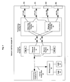
- Fig. 2 is a block diagram of the network interface adapter comprising the system of the present invention.
- Fig. 3 is a diagram showing the contents of a transmit status register used in the present invention.
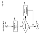
- Fig. 4 (comprising Figs. 4A and 4B) is a flow chart illustrating the method of determining the type of network and physical media of the present invention.
- Fig. 1 illustrates a workstation 10 comprising the automatic network and media type detection system of the present invention.
- the workstation 10 may be any type of processing machine but, in the preferred embodiment, it is a personal computer (PC), such as an IBM® PS/2® Model 90 personal computer.
- PC personal computer
- the workstation 10 comprises a system processor 12 for providing processing power, system memory 14 for providing memory space (normally random access memory (RAM)) in which the active workstation applications may be temporarily stored for easy access by the system processor 12, secondary memory 16 for providing a backing store (i.e., the hard disk), one or more removable adapter cards 18, each of which may provide a unique function, e.g., system memory expansion, internal modem for being connected to a transport network via external connector 28a, etc., for allowing the workstation to be suited for the user's needs, a network interface adapter 20 comprising the system of the present invention, and a system bus 21 (such as the IBM Micro Channel® bus) for allowing the various elements to communicate with one another. These elements provide a broad range of functionality to the user.
- system memory 14 for providing memory space (normally random access memory (RAM)) in which the active workstation applications may be temporarily stored for easy access by the system processor 12
- secondary memory 16 for providing a backing store (i.e., the hard disk)
- the network interface adapter 20 comprises a system bus interface 26 for providing an interface to the system bus 24 , a microprocessor 22 for providing processing power to the network interface adapter 20, RAM 23 for providing temporary storage for the microprocessor 22, ROM (read only memory) 24 for storing the microprocessor's instructions, an internal adapter bus 25, a protocol handler 34 and transceiving circuitry 30 to be discussed in greater detail.
- the adapter 20 further has external ports, or connectors, STP connector 28b, UTP connector 28c, Coax connector 28d, and AUI connector 28e for providing connectivity to the various networks.
- the network interface adapter 20 may also include other elements for providing additional function which are unrelated to the detection system of the present invention and are not shown.
- the connectors 28b, 28c, 28d and 28e provide physical connectivity to the various physical media that are available for network access. For instance, many times, a company will have a token ring network operating on shielded twisted pair (STP) or on unshielded twisted pair (UTP) wiring. UTP and STP wiring each consists of four copper conductors, each covered with insulation (usually polyvinyl chloride (PVC)), twisted about each other so that each is equally exposed to interfering signals picked up from the environment. This feature is especially important when differential transmission is used because, in differential transmission, information is conveyed by the difference in voltage between the two wires so that noise externally induced upon one will be equally induced upon the other having zero net effect.
- PVC polyvinyl chloride
- the shielding in STP increases the immunity to outside interference and may also be required if the circuitry driving the wire pair generates sufficient radio frequency interference (RFI) that shielding is necessary to comply with FCC regulations.
- Connectors 28b and 28c are adapted to receive token ring STP and UTP wiring, respectively.
- coaxial cable which consists of a copper conductor surrounded by insulation, which is in turn surrounded by a tube-shaped conductor of solid copper, solid aluminum, or metal braid, is used because of the wide bandwidth it offers. Because of its ability to transfer low-frequency voltage levels, even DC voltages, coax is especially useful in baseband LAN systems, such as the Ethernet CSMA/CD (“carrier sense multiple access with collision detection”) system, where the DC voltage level is used to detect collisions.
- Connector 28d is configured to be connected to another coaxial cable-type connector, such as a BNC connector.
- Attachment Unit Interface is another interface definition which may be utilized in a particular LAN environment.
- AUI which is defined by the IEEE 802.3 standard, is comprised of data out (DO), data in (DI), control out (CO) and control in (CI) circuits.
- DO data out
- DI data in
- CO control out
- CI control in circuits.
- AUI provides function in addition to the physical connectivity to the Ethernet LAN. For instance, the AUI provides the collision detection required in an Ethernet LAN environment.
- Connector 28e is configured to support an AUI.
- transceiving circuitry 30 Connected to the connectors 28b, 28c, 28d and 28e, by internal wiring STP 27b, UTP 27c, Coax 27d, and AUI 27e, is transceiving circuitry 30.
- transceiving circuitry will be used to represent the signal conversion device whose function is to convert digital data into a form suitable for transmission over the medium being used, and to convert signals received over the medium back into digital data. Transceiving circuitry is required because, despite the short distances spanned by LANs, the electrical characteristics of the media used and the possibility of electrical noise pickup preclude the use of conventional logic signaling levels such as would be used within computers attached to the network.
- LANs designed to cover a small area, such as a few offices
- line drivers and receivers perform adequate signal conditioning and provide adequate noise immunity. Many of these use signaling which meets the requirements of the EIA RS-232-C, RS-422, or RS-423 standards.
- Simple line drivers using either RS-422 or a proprietary design, are also used in some ring networks that use wire centers (or "hubs").
- Other LANs particularly those that operate at speeds above a megabit per second and/or cover a distance of more than a kilometer, utilize more elaborate signaling systems that require transceivers or modems.
- Transceivers perform a function similar to that of the line drivers used in smaller, slower systems, but transceivers span greater distances, provide a greater degree of electrical isolation, have improved noise rejection and are generally more complex and costly. Modems are used to transmit data great distances.
- Transceiving circuitry 30 comprises token ring transceiving circuitry 31 and Ethernet transceiving circuitry 32.
- the Ethernet transceiving circuitry 32 connected to the UTP, Coax and AUI ports 28c, 28d and 28e, respectively, provides the transceiving function for Ethernet LANs.
- Protocol handler 34 Connected to the transceiving circuitry 30 is a protocol handler 34.
- Protocol handler 34 conveys digital data to the transceiving circuitry 30 for conversion into a form suitable for transmission over the medium being used and receives digital data from the transceiving circuitry 30 received over the medium.
- Protocol handler 34 is responsible for a number of tasks for the transmission/reception of data to/from the network. Protocol handler 34 handles these tasks utilizing transmit function circuitry 36 and receive function circuitry 38. Before transmission begins, the protocol handler 34 must perform network access control functions.
- the transmit function circuitry 36 In a token ring or token bus, the transmit function circuitry 36 must await word from the receive function circuitry 38 that the token has been received while in CSMA/CD systems, the transmit function circuitry 36 must await the no-carrier condition (and the expiration of a time-out if a collision occurred on the previous transmission attempt). Further, the protocol handler34 performs other protocol specific functions such as formatting a frame to be transmitted via a network into the proper format as defined by the protocol. This includes, for example, adding starting and ending delimiters, and calculating the value of the cyclic reduncy check (CRC) and adding it to the CRC field.
- CRC cyclic reduncy check
- the transmit function circuitry 36 primarily monitors correct operation. In addition, in token ring, after a frame has been transmitted, the transmit function circuitry 36 must "strip" the transmitted frame from the network after it completes the ring. The status of the transmission can be detected based upon the "stripped" frame. The status of the transmission is stored by the transmit function circuitry 36 in a transmit status register (TSR 40) to be discussed in greater detail.
- TSR 40 transmit status register
- the transmit function circuitry's monitoring task begins immediately when transmission starts, as it must check the collision detection lead from the transceiver circuitry 30 to determine whether a collision has been detected. As with token ring, the status of the transmission is stored in the transmit status register 40.
- the protocol handler's receive function circuitry 38 must perform four tasks: finding the beginning of the message, address recognition, finding the end of the message, and (in some cases) checking the validity of the message. In addition to these functions, most LANs require the receiver to perform network operational integrity functions. The status of the reception is stored by the receive function circuitry 38 in a receive status register 42.
- the receive function circuitry 38 is not particularly relevant to the present invention so it will not be discussed any further.
- an LLC (Logical Link Control) "interrogation" frame is transmitted to each of the external connectors 28b, 28c, 28d and 28e, individually and in a predetermined order.
- the invention is described in terms of four connectors (28b, 28c, 28d and 28e) and two network protocols (token ring, Ethernet) only for the purposes of describing the invention. A greater number of connectors may be used supporting a greater number of network types using the present invention.
- the transmitted frame is termed an interrogation frame as its purpose is have an "interrogatation" of the system in order to determine which valid connections are made to the external ports 28b, 28c, 28d, 28e.
- a token ring network is connected to STP port 28b and/or to UTP port 28c, and whether an Ethernet network is connected to UTP port 28c, Coax port 28d, and/or AUI port 28e.
- the results of the individual transmissions are stored temporarily in the transmit status register 40, polled by the microprocessor 22, and stored for future use in RAM 23.
- the microprocessor 22 based upon code programmed in the ROM 24, requests that the protocol handler 34 transmit a specified LLC interrogation frame conforming to a specified protocol on a specified connector.
- microprocessor 22 may issue a request for an Ethernet LLC interrogation frame transmission to external connector 28c which is a connector for a UTP cable - connected either to a token ring network or an Ethernet network.
- the protocol handler 34 receives this request, builds the interrogation frame per the specified protocol's requirements (in this example, per the Ethernet standard (802.3)) and conveys the digital data to the transceiving circuitry 30 for conversion into a form suitable for transmission over the medium being used as defined by the external connector specified. For instance, where the Ethernet interrogation frame is being transmitted via external connector 28c, the Ethernet transceiving circuitry 32 converts the interrogation frame into a form suitable for transmission over the UTP medium.
- the transmit function circuitry 36 monitors the results of the transmission. The status of the transmission is stored by the transmit function circuitry 36 in the transmit status register 40.
- the microprocessor retrieves this status from the protocol handler 34, stores it in RAM 23 and requests that an interrogation frame be issued to the next external connector, to the Ethernet AUI connector 28e, for instance.
- the transmit function circuitry 36 monitors the results of the transmission and stores the status transmission in the transmit status register 40.
- the microprocessor retrieves this status from the protocol handler 34, stores it in RAM 23 and requests that an interrogation frame be issued to the next external connector, and so forth, until all of the connectors and protocols have been tested.
- the microprocessor 22 can determine which connectors, if any, are connected into a network and, if so, to which type of network are they connected. For instance, with regard to connector 28c, in this example, there three possible conditions: (1) no cable is connected to the connector 28c; (2) a UTP cable is connected to connector 28c at one end and to a token ring concentrator at the other end; and (3) a UTP cable is connected to connector 28c at one end and to a Ethernet network at the other end. Based upon the contents of the transmit status register 40 after the various interrogation frame transmissions via these connectors, the valid network connections to the adapter can be "sensed" and the adapter can be automatically configured. The detailed flow chart of this method is illustrated in Fig. 4 (comprising Figs. 4A and 4B) to be discussed below.
- the fields are as follows:
- the Protocol Handler 34 has the responsibility of creating and calculating (in the case of FCS) the CSMA/CD and token ring specific fields, i.e., the Preamble, SFD, and FCS for CSMA/CD and SD, FCS, ED and FS for token ring, and assembling the interrogation frame for transmission via the appropriate connector.
- FCS Fibre Channel Service
- the format is shown in Table 2.
- the AC/FC fields (having the contents of "1040"), in the token ring interrogation frame only, indicates the interrogation frame's priority, that the interrogation frame is not a token, and that the interrogation frame is an LLC frame.
- Both the DA and SA fields comprise the adapter's address so that no other station on any connected network will attempt to receive the interrogation frame (as it is merely for interrogation purposes).
- the remainder of the interrogation frame is filled with 0s so that the minimum frame size for CSMA/CD requirements is reached.
- Fig. 3 illustrates a sample format of the transmit status register 40 shown in Fig. 2.
- the transmit status register 40 comprises 16 bits, bit 0 through bit 15. The state of each one of these bits may be checked and its contents reported to the microprocessor 22 by the transmit function circuitry 36 upon request of the microprocessor 22.
- bit definitions are shown in Table 3 below: TABLE 3 Bit Definition Protocol 0 Frame Copy Indicator FCI Token-ring 1 Strip Frame Error Detection Indicator (SF EDI) Token-ring 2 Strip Frame Error (SFE) Token-ring 3 Transmit Completion Code Token-ring/Ethernet 4 Transmit Completion Code Token-ring/Ethernet 5 Transmit Completion Code Token-ring/Ethernet 6 Transmit Completion Code Token-ring/Ethernet 7 Excessive Deferral (ED) Ethernet 8 No Carrier Sense (NCS) Ethernet 9 Carrier Sense Lost (CSL) Ethernet 10 Out of Window Collision (OWC) Ethernet 11 Excessive Collision (EC) Unused 12 Don't care Unused 13 Don't care Unused 14 Don't care Unused 15 Don't care Unused A breakout of the bit representations is given below:
- the transmit function circuitry 36 sets or resets the bits in the transmit status register 40 based upon the status of a transmission. For instance, in CSMA/CD, if there are excessive collisions detected by the adapter, bit 11 (Excessive Collision) is set by the transmit function circuitry 36.
- the contents of the transmit status register are shown when: 1) when there is a successful token ring interrogation frame transmission, i.e., the LLC interrogation frame was transmitted via one of the token ring ports (STP 28b or UTP 28c) and was successfully received by the adapter (via the lobe wrap) and stripped from the network by the adapter; and 2) when there is a successful Ethernet interrogation frame transmission via any of ports UTP 28c, Coax 28d and AUI 28e.
- a successful token ring interrogation frame transmission i.e., the LLC interrogation frame was transmitted via one of the token ring ports (STP 28b or UTP 28c) and was successfully received by the adapter (via the lobe wrap) and stripped from the network by the adapter; and 2) when there is a successful Ethernet interrogation frame transmission via any of ports UTP 28c, Coax 28d and AUI 28e.
- the interrogation frame is transmitted to either STP connector 28b or UTP connector 28c. If a token ring cable is connected between the connector and a concentrator, a standard "lobe wrap" is established in the concentrator (or in the cable in the case of STP cabling). With lobe wrap, the transmitted interrogation frame is wrapped back to the connector. Where a token ring cable is properly installed between the connector and the concentrator, all of the token ring bits of the transmit status register (bits 0-6) will be reset, or "0".
- the FCI will not be set because no other station has received the interrogation frame to copy it
- SF EDI will not be set because no other station has received the interrogation frame to detect an error
- SFE will not be set as the interrogation frame should be a valid length
- the transmit completion code should be zero indicating a successful transmit, e.g., no internal adapter errors were detected.
- a flowchart 100 illustrating the method of the present invention begins at 102.
- the Ethernet transceiving circuitry 32 transmits the interrogation frame (illustrated above) on UTP 27c to connector UTP 28c.
- the microprocessor 22 checks the transmit status register 40 to determine whether the interrogation frame transmission was a success, i.e., does the transmit register contents match those of Table 4. If so, at 108, this configuration (that an Ethernet network is attached to the UTP connector 28c) is recorded in RAM 23.
- this configuration that an Ethernet network is attached to the UTP connector 28c
- the Ethernet transceiving circuitry 32 transmits the interrogation frame on AUI 28e.
- the microprocessor 22 checks the transmit status register 40 to determine whether the interrogation frame transmission was a success and, if so, at 114, records this configuration in RAM 23.
- the token ring transceiving circuitry 31 transmits the interrogation frame on STP 28b.
- the microprocessor 22 checks the transmit status register 40 to determine whether the interrogation frame transmission was a success and, if so, at 120, records this configuration in RAM 23.
- the microprocessor 22 determines whether the previously conducted Ethernet UTP test was successful, and if so, skips the token ring UTP test (steps 124, 126, and 128) to step 130 because an Ethernet network is connected to that connector.
- the token ring transceiving circuitry 31 transmits the interrogation frame on the UTP connector 28c.
- the microprocessor 22 checks the transmit status register 40 to determine whether the interrogation frame transmission was a success and, if so, at 128, records this configuration in RAM 23. The flow diagram to this method is continued at B 130 in Fig. 4B.
- the Ethernet transceiving circuitry 31 transmits the interrogation frame on coax 28d.
- the microprocessor 22 checks the transmit status register 40 to determine whether the interrogation frame transmission was a success and, if so, at 136, records this configuration in RAM 23.
- the results of each of the tests for the external connectors are stored in RAM 23. These results represent the present configuration of the adapter card regarding to which network(s) it is connected. This configuration can be sent to the system processor 12 of workstation 10 (Fig. 1) after the tests are completed. In this way, the system processor 12 is aware of the resources available to it and can manage its own resources accordingly.
- the method described above can be performed at any time as it requires no manual intervention such as connecting or disconnecting cables and, because of the interrogation frame format, no disruption of a connected network will occur.
- the method and system of the present invention allows network workstations to automatically "sense" its present physical configuration in one or more networks without any manual intervention.
- the various networks e.g., token ring, Ethernet
- the workstation may be physically connected to any available network (that is supported by the adapter of the present invention) and be automatically configured without the user needing to know any of the details of the physical connectivity.
Landscapes
- Engineering & Computer Science (AREA)
- Computer Networks & Wireless Communication (AREA)
- Signal Processing (AREA)
- Computer Security & Cryptography (AREA)
- Small-Scale Networks (AREA)
- Communication Control (AREA)
Applications Claiming Priority (2)
| Application Number | Priority Date | Filing Date | Title |
|---|---|---|---|
| US262197 | 1994-06-20 | ||
| US08/262,197 US5497460A (en) | 1994-06-20 | 1994-06-20 | System and method for determining network connectivity |
Publications (2)
| Publication Number | Publication Date |
|---|---|
| EP0689327A2 true EP0689327A2 (de) | 1995-12-27 |
| EP0689327A3 EP0689327A3 (de) | 1998-03-18 |
Family
ID=22996577
Family Applications (1)
| Application Number | Title | Priority Date | Filing Date |
|---|---|---|---|
| EP95480067A Withdrawn EP0689327A3 (de) | 1994-06-20 | 1995-05-19 | System und Verfahren zur Bestimmung der Netzverbindungsmöglichkeit |
Country Status (3)
| Country | Link |
|---|---|
| US (1) | US5497460A (de) |
| EP (1) | EP0689327A3 (de) |
| JP (1) | JPH088958A (de) |
Cited By (5)
| Publication number | Priority date | Publication date | Assignee | Title |
|---|---|---|---|---|
| EP0844769A1 (de) * | 1996-11-20 | 1998-05-27 | Kabushiki Kaisha Toshiba | Verfahren und Vorrichtung zur Netzwerkverbindung |
| EP0767565A3 (de) * | 1995-10-06 | 1998-10-21 | Canon Kabushiki Kaisha | Dynamische Netzwerkmediatypbestimmung |
| GB2340699A (en) * | 1998-08-11 | 2000-02-23 | Ibm | Automatic network protocol configuration in a data processing system |
| GB2356521A (en) * | 1999-07-20 | 2001-05-23 | Yat Sing Philip Poon | Multimedia network has protocol conversion |
| WO2005020537A1 (de) * | 2003-08-24 | 2005-03-03 | Nova Informationstechnik Gmbh | Verfahren und vorrichtung zum aufbau eines virtuellen elektronischen lehrsystems mit individueller interaktiver kommunikation |
Families Citing this family (41)
| Publication number | Priority date | Publication date | Assignee | Title |
|---|---|---|---|---|
| US5675735A (en) * | 1994-06-29 | 1997-10-07 | Digital Equipment Corporation | Method and apparatus for interconnecting network devices in a networking hub |
| US5680397A (en) * | 1995-03-13 | 1997-10-21 | International Business Machines Corporation | Multi-port LAN switch for a token-ring network |
| US6282712B1 (en) * | 1995-03-10 | 2001-08-28 | Microsoft Corporation | Automatic software installation on heterogeneous networked computer systems |
| US5802286A (en) * | 1995-05-22 | 1998-09-01 | Bay Networks, Inc. | Method and apparatus for configuring a virtual network |
| US5802041A (en) * | 1995-05-31 | 1998-09-01 | International Business Machines Corporation | Monitoring ethernet lans using latency with minimum information |
| US5793953A (en) | 1995-07-07 | 1998-08-11 | Sun Microsystems, Inc. | Method and apparatus for allowing packet data to be separated over multiple bus targets |
| US6115747A (en) * | 1995-11-13 | 2000-09-05 | Roger E. Billings | Computer network interface that merges remote data received from other computers with local data before transmitting the merged data to a network |
| US5708778A (en) * | 1996-05-09 | 1998-01-13 | Sun Microsystems, Inc. | Automatic configuration of protocol parameters in protocol layers for public area networks |
| US5894551A (en) * | 1996-06-14 | 1999-04-13 | Huggins; Frank | Single computer system having multiple security levels |
| US5859970A (en) * | 1996-08-27 | 1999-01-12 | Telxon Corporation | Portable computer with internal ethernet/token ring controller |
| US6262993B1 (en) * | 1996-11-08 | 2001-07-17 | Kevin Kirmse | Computer and peripheral networking device permitting the practical use of buffer insertion-based networks while communicating over unshielded twisted pair conductive media |
| US6504851B1 (en) * | 1997-11-21 | 2003-01-07 | International Business Machines Corporation | Dynamic detection of LAN network protocol |
| WO1999053627A1 (en) | 1998-04-10 | 1999-10-21 | Chrimar Systems, Inc. Doing Business As Cms Technologies | System for communicating with electronic equipment on a network |
| US6959451B1 (en) * | 1998-08-21 | 2005-10-25 | Intel Corporation | Transmission communications management |
| US6484213B1 (en) * | 1998-09-09 | 2002-11-19 | Compaq Information Technologies Group, Inc. | Adapting networking device for enhancing performance of a hybrid networking system |
| US6202095B1 (en) | 1998-10-07 | 2001-03-13 | International Business Machines Corporation | Defining characteristics between processing systems |
| US6332166B1 (en) | 1998-12-16 | 2001-12-18 | International Business Machines Corporation | Adaptive interface apparatus and method for data terminal elements in a communication network transmitting and receiving ethernet over a shielded twisted pair cabling system |
| US6724729B1 (en) * | 1998-12-30 | 2004-04-20 | Finisar Corporation | System analyzer and method for synchronizing a distributed system |
| US6381642B1 (en) * | 1999-10-21 | 2002-04-30 | Mcdata Corporation | In-band method and apparatus for reporting operational statistics relative to the ports of a fibre channel switch |
| US6975597B1 (en) * | 2000-02-11 | 2005-12-13 | Avaya Technology Corp. | Automated link variant determination and protocol configuration for customer premises equipment and other network devices |
| EP1266462A2 (de) * | 2000-02-23 | 2002-12-18 | Tantivy Communications, Inc. | Festlegung der anfangsleistung in aufwärtsrichtung |
| US6973077B1 (en) * | 2000-07-17 | 2005-12-06 | 3Com Corporation | Method and apparatus for auto-detection of LAN, Modem, or ISDN utilizing a common connection to a peripheral component |
| GB0025297D0 (en) * | 2000-10-14 | 2000-11-29 | Ibm | A network interface device |
| US6892151B1 (en) | 2001-09-19 | 2005-05-10 | Applied Micro Circuits Corporation | Methods and apparatus for determining whether electronic devices are communicatively compatible |
| US6912595B2 (en) * | 2001-10-19 | 2005-06-28 | Znyx Networks, Inc. | Noise suppresion for network transceivers |
| US7127299B2 (en) * | 2001-10-23 | 2006-10-24 | Medtronic, Inc. | Network communications arrangement for IMD programming units |
| US7401162B2 (en) * | 2003-07-22 | 2008-07-15 | Psion Teklogix Inc. | Multi-functional port |
| JP4712330B2 (ja) * | 2003-09-12 | 2011-06-29 | 株式会社リコー | 通信装置、通信システム、通信方法及びプログラム |
| JP2011072046A (ja) * | 2003-09-12 | 2011-04-07 | Ricoh Co Ltd | 証明書設定方法 |
| US8631163B1 (en) * | 2003-12-11 | 2014-01-14 | At&T Intellectual Property Ii, L.P. | Automatic connectivity determiner and configurator |
| US20050144287A1 (en) | 2003-12-11 | 2005-06-30 | International Business Machines Corporation | Computer product and system for establishing network connections |
| US20060013246A1 (en) * | 2004-07-13 | 2006-01-19 | International Business Machines Corporation | System, apparatus and method for gigabit ethernet communications over an IBM cabling system |
| US7532647B2 (en) | 2004-07-14 | 2009-05-12 | Tekelec | Methods and systems for auto-correlating message transfer part (MTP) priority and internet protocol (IP) type of service in converged networks |
| US7411405B2 (en) * | 2004-11-03 | 2008-08-12 | Panduit Corp. | Method and apparatus for reliable network cable connectivity |
| US8352632B2 (en) * | 2005-10-26 | 2013-01-08 | Level 3 Communications, Llc | Systems and methods for discovering network topology |
| US8160062B2 (en) * | 2006-01-31 | 2012-04-17 | Microsoft Corporation | Network connectivity determination based on passive analysis of connection-oriented path information |
| US8677479B2 (en) * | 2007-04-16 | 2014-03-18 | Microsoft Corporation | Detection of adversaries through collection and correlation of assessments |
| US8954551B2 (en) * | 2008-03-17 | 2015-02-10 | Microsoft Corporation | Virtualization of groups of devices |
| US8218433B2 (en) * | 2009-01-07 | 2012-07-10 | Alcatel Lucent | Monitoring connectivity in ring networks |
| CN102461085B (zh) * | 2009-06-12 | 2014-10-29 | 三菱电机株式会社 | 通信管理装置、通信节点以及数据通信方法 |
| TWI792684B (zh) * | 2021-11-17 | 2023-02-11 | 瑞昱半導體股份有限公司 | 資料傳輸方法以及資料傳輸系統 |
Family Cites Families (17)
| Publication number | Priority date | Publication date | Assignee | Title |
|---|---|---|---|---|
| US4999833A (en) * | 1985-05-06 | 1991-03-12 | Itt Corporation | Network connectivity control by artificial intelligence |
| AU634192B2 (en) * | 1988-11-14 | 1993-02-18 | Datapoint Corporation | Lan with dynamically selectable multiple operational capabilities |
| US5247464A (en) * | 1989-05-25 | 1993-09-21 | Digital Equipment Corporation | Node location by differential time measurements |
| US5247517A (en) * | 1989-10-20 | 1993-09-21 | Novell, Inc. | Method and apparatus for analyzing networks |
| US5301303A (en) * | 1990-04-23 | 1994-04-05 | Chipcom Corporation | Communication system concentrator configurable to different access methods |
| US5117422A (en) * | 1990-07-09 | 1992-05-26 | Itt Corporation | Method for providing an efficient and adaptive management of message routing in a multi-platform and apparatus communication system |
| US5265241A (en) * | 1990-09-04 | 1993-11-23 | International Business Machines Corporation | Method and apparatus for verifying the configuration of a link-connected network |
| US5195085A (en) * | 1990-09-11 | 1993-03-16 | At&T Bell Laboratories | Communication link identifier |
| JPH04127743A (ja) * | 1990-09-19 | 1992-04-28 | Fujitsu Ltd | 広帯域isdnにおける伝送路試験方式 |
| US5208803A (en) * | 1990-11-19 | 1993-05-04 | Ag Communication Systems Corporation | Circuit for testing digital lines |
| US5285449A (en) * | 1991-04-03 | 1994-02-08 | International Business Machines Corporation | Protocol for hybrid local area networks |
| US5317568A (en) * | 1991-04-11 | 1994-05-31 | Galileo International Partnership | Method and apparatus for managing and facilitating communications in a distributed hetergeneous network |
| US5222062A (en) * | 1991-10-03 | 1993-06-22 | Compaq Computer Corporation | Expandable communication system with automatic data concentrator detection |
| GB2264845B (en) * | 1992-02-28 | 1995-09-20 | Texas Instruments Ltd | Local area network adaptive circuit for multiple network types |
| US5251213A (en) * | 1992-05-12 | 1993-10-05 | Microcom Systems, Inc. | Multiport source routing token ring bridge apparatus |
| US5410535A (en) * | 1992-07-02 | 1995-04-25 | Digital Equipment Corporation | Automatic selection of an interface for ethernet stations |
| US5379296A (en) * | 1992-12-31 | 1995-01-03 | Unisys Corporation | Method and apparatus for interfacing a workstation to a plurality of computer platforms |
-
1994
- 1994-06-20 US US08/262,197 patent/US5497460A/en not_active Expired - Lifetime
-
1995
- 1995-03-22 JP JP7062433A patent/JPH088958A/ja active Pending
- 1995-05-19 EP EP95480067A patent/EP0689327A3/de not_active Withdrawn
Non-Patent Citations (1)
| Title |
|---|
| None |
Cited By (7)
| Publication number | Priority date | Publication date | Assignee | Title |
|---|---|---|---|---|
| EP0767565A3 (de) * | 1995-10-06 | 1998-10-21 | Canon Kabushiki Kaisha | Dynamische Netzwerkmediatypbestimmung |
| EP0844769A1 (de) * | 1996-11-20 | 1998-05-27 | Kabushiki Kaisha Toshiba | Verfahren und Vorrichtung zur Netzwerkverbindung |
| US6157650A (en) * | 1996-11-20 | 2000-12-05 | Kabushiki Kaisha Toshiba | Method and apparatus for connecting network |
| GB2340699A (en) * | 1998-08-11 | 2000-02-23 | Ibm | Automatic network protocol configuration in a data processing system |
| GB2356521A (en) * | 1999-07-20 | 2001-05-23 | Yat Sing Philip Poon | Multimedia network has protocol conversion |
| WO2005020537A1 (de) * | 2003-08-24 | 2005-03-03 | Nova Informationstechnik Gmbh | Verfahren und vorrichtung zum aufbau eines virtuellen elektronischen lehrsystems mit individueller interaktiver kommunikation |
| US7840649B2 (en) | 2003-08-24 | 2010-11-23 | Nova Informationstechnik Gmbh | Method and device for setting up a virtual electronic teaching system with individual interactive communication |
Also Published As
| Publication number | Publication date |
|---|---|
| US5497460A (en) | 1996-03-05 |
| EP0689327A3 (de) | 1998-03-18 |
| JPH088958A (ja) | 1996-01-12 |
Similar Documents
| Publication | Publication Date | Title |
|---|---|---|
| US5497460A (en) | System and method for determining network connectivity | |
| US4858112A (en) | Interface comprising message and protocol processors for interfacing digital data with a bus network | |
| CN100473066C (zh) | 简化的硬件网络适配器和通信方法 | |
| US5550803A (en) | Method and system for increasing network information carried in a data packet via packet tagging | |
| US7496671B2 (en) | Self-configuring communications module adaptive to different host system types | |
| US5305317A (en) | Local area network adaptive circuit for multiple network types | |
| USRE36182E (en) | Apparatus and method for switching ethernet media type | |
| US7653014B2 (en) | Configuring a transmission mode between devices | |
| US5289474A (en) | Communication network interface testing system | |
| JPH10164107A (ja) | データ通信方法、電子機器、及び物理層集積回路 | |
| IE922101A1 (en) | Multiplexing scheme for modem control signals | |
| EP1111513A2 (de) | System und Verfahren zur geraeuscharme Steuerung von Radiofrequenzgeräten | |
| US4943978A (en) | Digital interface unit | |
| EP0228250A2 (de) | Kopplungsunterscheider | |
| US20030179719A1 (en) | Method and apparatus for transmitting packets at a transfer rate that depends on a response from a destination | |
| US4954965A (en) | Enhanced frame utilization for CSMA/CD communication protocol | |
| EP0073352B1 (de) | Datenverkehrssystem | |
| US20180276166A1 (en) | Coupler for an automation system | |
| WO1987005767A1 (en) | Communication system having a control channel and an image channel | |
| US6295280B1 (en) | Method for network node recognition | |
| US5819113A (en) | Method of identifying end of pocket by writing the address of last data into the first location of the memory | |
| EP0567342A2 (de) | Signalschnittstelle zur Verbindung einer Netzeingangsschaltung mit einer Netzadapterschaltung | |
| US5751974A (en) | Contention resolution for a shared access bus | |
| EP0226963A2 (de) | Datenvermittlung für kombiniertes Bus- und Sternnetzwerk | |
| EP0474380B1 (de) | Verfahren und Gerät zur Überwachung eines Netzes |
Legal Events
| Date | Code | Title | Description |
|---|---|---|---|
| PUAI | Public reference made under article 153(3) epc to a published international application that has entered the european phase |
Free format text: ORIGINAL CODE: 0009012 |
|
| AK | Designated contracting states |
Kind code of ref document: A2 Designated state(s): DE FR GB |
|
| PUAL | Search report despatched |
Free format text: ORIGINAL CODE: 0009013 |
|
| AK | Designated contracting states |
Kind code of ref document: A3 Designated state(s): DE FR GB |
|
| 18D | Application deemed to be withdrawn |
Effective date: 19980203 |