EP0689495B1 - Planierhammer - Google Patents
Planierhammer Download PDFInfo
- Publication number
- EP0689495B1 EP0689495B1 EP94911209A EP94911209A EP0689495B1 EP 0689495 B1 EP0689495 B1 EP 0689495B1 EP 94911209 A EP94911209 A EP 94911209A EP 94911209 A EP94911209 A EP 94911209A EP 0689495 B1 EP0689495 B1 EP 0689495B1
- Authority
- EP
- European Patent Office
- Prior art keywords
- hammer
- tip
- handle
- coupling part
- hammer according
- Prior art date
- Legal status (The legal status is an assumption and is not a legal conclusion. Google has not performed a legal analysis and makes no representation as to the accuracy of the status listed.)
- Expired - Lifetime
Links
- 229910000831 Steel Inorganic materials 0.000 claims abstract description 8
- 239000002184 metal Substances 0.000 claims abstract description 8
- 229910052751 metal Inorganic materials 0.000 claims abstract description 8
- 239000010959 steel Substances 0.000 claims abstract description 8
- 229910000760 Hardened steel Inorganic materials 0.000 claims description 3
- 238000006073 displacement reaction Methods 0.000 claims description 3
- 230000008878 coupling Effects 0.000 claims 7
- 238000010168 coupling process Methods 0.000 claims 7
- 238000005859 coupling reaction Methods 0.000 claims 7
- 238000009499 grossing Methods 0.000 claims 1
- 230000000694 effects Effects 0.000 description 5
- 238000005452 bending Methods 0.000 description 3
- 235000020303 café frappé Nutrition 0.000 description 3
- 230000000593 degrading effect Effects 0.000 description 3
- 239000003973 paint Substances 0.000 description 3
- 239000011248 coating agent Substances 0.000 description 2
- 238000000576 coating method Methods 0.000 description 2
- 230000007547 defect Effects 0.000 description 2
- 239000000463 material Substances 0.000 description 2
- OKTJSMMVPCPJKN-UHFFFAOYSA-N Carbon Chemical compound [C] OKTJSMMVPCPJKN-UHFFFAOYSA-N 0.000 description 1
- 235000008733 Citrus aurantifolia Nutrition 0.000 description 1
- 241000277275 Oncorhynchus mykiss Species 0.000 description 1
- 235000011941 Tilia x europaea Nutrition 0.000 description 1
- HCHKCACWOHOZIP-UHFFFAOYSA-N Zinc Chemical compound [Zn] HCHKCACWOHOZIP-UHFFFAOYSA-N 0.000 description 1
- 229910052799 carbon Inorganic materials 0.000 description 1
- 238000006243 chemical reaction Methods 0.000 description 1
- 238000001962 electrophoresis Methods 0.000 description 1
- 230000001939 inductive effect Effects 0.000 description 1
- 239000010410 layer Substances 0.000 description 1
- 239000004571 lime Substances 0.000 description 1
- 239000013521 mastic Substances 0.000 description 1
- 238000000034 method Methods 0.000 description 1
- 230000002093 peripheral effect Effects 0.000 description 1
- 239000002344 surface layer Substances 0.000 description 1
- 239000002335 surface treatment layer Substances 0.000 description 1
- 238000011282 treatment Methods 0.000 description 1
- 239000002023 wood Substances 0.000 description 1
- 229910052725 zinc Inorganic materials 0.000 description 1
- 239000011701 zinc Substances 0.000 description 1
Images

Classifications
-
- B—PERFORMING OPERATIONS; TRANSPORTING
- B25—HAND TOOLS; PORTABLE POWER-DRIVEN TOOLS; MANIPULATORS
- B25D—PERCUSSIVE TOOLS
- B25D1/00—Hand hammers; Hammer heads of special shape or materials
Definitions
- the present invention relates to tools for leveling a sheet of steel or other metal, in particular a sheet of automobile body.
- planing is carried out either with a wooden mallet or with a planing hammer.
- the advantage of the wooden mallet is that it does not lengthen the molecules of the sheet during striking.
- the mallet restores the general shape of the sheet, crushing any folds formed in the sheet during its deformation.
- the folds are still visible after planing, and the surface appearance is not satisfactory. Additional operations are required.
- planing hammers currently used include a handle secured to a steel head with a flat table. With such a hammer we strike on the sheet placed on a plate or on a pile. This results in a flattening, but also an elongation of the sheet.
- a body sheet includes, on its external surface or surfaces, treatments such as zinc coating, electrophoresis, application of primers and paints. These surface treatment layers disturb the reactions of the sheet during planing, by modifying its elongation.
- planing a sheet is a difficult operation, requiring a skilled workforce that must be trained during a particularly long apprenticeship.
- Document AT-B-366 311 describes a hammer for cold and hot drawing of body sheets.
- the hammer includes a striking surface curved lengthwise concavely, and shaped like a bastard-sized file.
- Such a structure is not suitable for leveling, because it produces not only an undesirable stretching of the sheet but also a bending of the sheet in the direction of the length of the hammer and an unacceptable marking of the surface of the sheet.
- the striking surface is off-center with respect to its connection on the handle, inducing a tendency to rebound, and no means allows the bending of said connection in the direction of the length.
- the documents FR-A-2 350 177 and DE-A-2 461 247 describe a planing hammer whose planar and centered striking surface, with radial ribs, pivots to exert upon impact a rotary force on the surface of sheet metal to work.
- the disadvantage is a significant increase in the complexity and mass of the hammer head, yes includes several moving parts between them to induce the rotational movement.
- the problem proposed by the present invention is to design a new efficient, simple and inexpensive structure of a body sheet leveling tool, producing a leveling effect without appreciable stretching of the sheet.
- the tool head must be in one piece, devoid of parts in relative rotation.
- This tool must be able to be used by any individual with a minimum of training, to produce a leveling of sheet metal while degrading as little as possible its external surface.
- the sheet thus planed can be directly painted without covering of mastic, with a simple operation of finishing with the file.
- the tool of the invention makes it possible to plan the sheet in the only zone which has been deformed, without there being any need to act on the sheet surface beyond the deformed zone. The leveling operation can thus be considerably shortened.
- Another desired effect is a certain tolerance of position of the hand of the user, to ensure a good leveling effect even in the case of a slight inclination of the tool handle in the anteroposterior plane during impact. Simultaneously, the tool adapts to the gestural habits of the user, and avoids any tendency to rebound.
- the multiple grooves of the table form a double-sized file surface, with two families of parallel grooves angularly offset from one another.
- the intermediate connecting part has a reduced dimension in the longitudinal direction of the hammer, capable of flexing elastically under stress, thus allowing slight angular displacements between the table and the handle in the longitudinal plane of symmetry of the hammer.
- These deformations favor a good distribution of the pressure forces on the sheet by the entire surface of the table, ensuring a certain tolerance of position of the hand of the user.
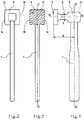
- the planing hammer comprises a handle 1, generally of wood or other equivalent material, secured to a head 2 generally of steel.
- the head 2 comprises a table 3, or surface intended to strike the sheet, a connection part to the handle 20, and an intermediate connection part 6 connecting the table 3 to the connection part to the handle 20.
- the connection part to the handle 20 conventionally comprises a light 4 in which the end of the handle 1 engages, a wedge 5 being forcibly engaged in the end of the handle 1, to block the end of the handle 1 in the light 4.
- the striking surface of the table 3 is advantageously generally planar, or slightly convex preferably along an axis of longitudinal convexity situated in the longitudinal plane of symmetry I-I of the hammer.
- the striking surface of the table 3 is moreover substantially centered on the axis of inertia III-III of the intermediate connecting part 6.
- the intermediate connection part 6 has a reduced dimension E in the longitudinal direction of the hammer.
- the reduction in dimension E with respect to the length of the table 3 gives this intermediate connecting part 6 a capacity to flex elastically under stress, allowing slight angular displacements between the table 3 and the handle 1 in the longitudinal plane of symmetry Hammer II.
- the dimension F in the transverse direction of the intermediate connecting part 6 can be reduced, for similar effects of elastic deflection under stress.
- the reduced section of this intermediate part 6 can advantageously be between one tenth and one quarter of the surface of the table 3.
- Table 3 constituting the surface striking against the sheet to be leveled, must be particularly hard to resist deformation and wear.
- the table 3 is made of hardened steel hardness, for example a 34 Mo Cr Ni 15 steel, with a carbon content of between 0.3 and 0.38 by weight, and of hardness, for example, of between 50 and 55 HRC approximately.
- the intermediate section 6 of reduced section must be able to deform slightly by angular bending, and it may then be preferable to use the same steel but hardened with lower hardness and greater elasticity, for example a hardness of 30 to 35 HRC about.
- the table 3 has a striking surface in steel with multiple grooves, shaped like a file.
- Figure 6 illustrates a form of file groove. At least one family of parallel grooves is made such as grooves 7, 8 and 9, each groove such that groove 7 is formed from two opposite faces 10 and 11 respectively. The face 10 is much more abrupt than the face 11, so that the teeth formed between the grooves tend to induce stresses in the material of the sheet in a preferred direction.
- the file is moved in the direction of arrow 12, to remove chips in the sheet 13.
- the multiple grooves of the striking surface of the table 3 form a double-sized file surface. Two families of parallel grooves are then provided angularly offset from one another.
- the two families of parallel grooves are preferably oriented respectively on either side of the longitudinal plane of symmetry I-I of the hammer to be planed.
- a first family of grooves oriented at an angle A of approximately 70 ° relative to the longitudinal plane of symmetry II has been shown, for example, and a second family of grooves oriented at an angle of 45 ° approximately with respect to the longitudinal plane of symmetry II.
- the grooves can advantageously be oriented so that the least steep face 11 is closest to the handle 1, the steepest face 10 being opposite and being farther from the handle 1, so as to compensate for the effect of the centrifugal force on head 2 of the hammer.
- a different or opposite orientation can however be chosen, depending on the user's preferences.
- the table has a square or rectangular outline, with two sides 14 and 15 substantially parallel to the median longitudinal axis II-II of the handle 1.
- Table dimensions 3 of about 3 , 4 x 3.4 cm, or about 4 x 3 cm, are embodiments suitable for frequent use in bodywork.
- the table 3 has a circular outline.
- the diameter of the table can commonly be between 30 and 40 millimeters approximately.
- the whole of head 2 and table 3 has a weight of between 100 and 400 grams approximately.
- the distance D between the table 3 and the median axis II-II of the handle 1 is between 40 and 65 millimeters approximately, advantageously equal to approximately 53 millimeters.
- planing hammer according to the invention, one can act on a sheet without degrading its surface condition, and in particular one can act on such a sheet by degrading only the layer of surface paint.
- a simple subsequent pass of the file is enough to obtain a perfectly smooth surface, ready to receive a coating of filling primers and paints.
- the use of the hammer according to the invention makes it possible to better see the remaining defects during the leveling of a sheet, in order to act only on the zones presenting these defects.
- the tool according to the invention allows the leveling of a sheet by appreciably limiting its elongation.
- the action on a deformed area does not disturb the peripheral areas of the sheet, so that the repair can be limited to the only deformed area, without the need to extend the action area of the tool.
Landscapes
- Engineering & Computer Science (AREA)
- Mechanical Engineering (AREA)
- Percussive Tools And Related Accessories (AREA)
- Straightening Metal Sheet-Like Bodies (AREA)
- Vehicle Cleaning, Maintenance, Repair, Refitting, And Outriggers (AREA)
Claims (10)
- Planierhammer für das Richten von Metallblechen, insbesondere Blechen von Kfz-Karosserien, bei dem ein Stiel (1) mit einem Kopf (2) verbunden ist, bestehend aus einem Verbindungsteil mit dem Stiel (20), einer Platte (3) und einem Zwischenstuck (6) zwischen der Platte (3) und dem Verbindungsteil mit dem Stiel (20), wobei die Platte (3) eine Schlagfläche aufweist, die hauptsächlich auf die Trägheitsachse (III-III) des Zwischenstücks (6) zentriert ist, dadurch gekennzeichnet, daß :- die Schlagfläche der Platte (3) aus mehrfach gerilltem Stahl wie eine Feile gestaltet ist,- die Schlagfläche der Platte (3) glatt oder leicht konvex ist.
- Hammer nach Anspruch 1, dadurch gekennzeichnet, daß die Schlagfläche der Platte (3) wie eine Feile in Zwischengröße, Halbschlicht- oder Schlichtfeile gestaltet ist.
- Hammer nach Anspruch 2, dadurch gekennzeichnet, daß die mehrfachen Rillen der Schlagfläche der Platte (3) eine Feilfläche mit Doppelfeile mit zwei winkelförmig von einander versetzten Parallelrillengruppen bilden, die jeweils auf beiden Seiten zur Längssymmetrieebene (I-I) des Hammers ausgerichtet sind.
- Hammer nach Anspruch 3, dadurch gekennzeichnet, daß die beiden Parallelrillengruppen jeweils nach ca. 45° (B) Winkel und ca. 70° (A) Winkel auf beiden Seiten der Längssymmetrieebene (I-I) des Hammers ausgerichtet sind.
- Hammer nach Anspruch 3 oder 4, dadurch gekennzeichnet, daß die Parallelrillengruppen so ausfallen, daß jede Rille (7) aus zwei gegenüberliegenden Seiten (10, 11) besteht, wobei die Seite (11) sich naher am Stiel (1) befindet und weniger steil als die gegenüberliegende Seite (10) ausfällt.
- Hammer nach einem der Ansprüche 1 bis 5, dadurch gekennzeichnet, daß das Zwischenstück (6) in Hammerlängsrichtung eine reduzierte Abmessung (E) aufweist, die sich bei Beanspruchung elastisch durchbiegen kann und somit kleine Winkelverschiebungen zwischen der Platte (3) und dem Stiel (1) in Längssymmetrieebene (I-I) des Hammers erlaubt.
- Hammer nach Anspruch 6, dadurch gekennzeichnet, daß die Platte (3) aus hochfestem gehärtetem Stahl besteht wohingegen das Zwischenstück (6) mit reduziertem Querschnitt aus weniger hartem und höchster elastischerem Härtestahl besteht.
- Hammer nach Anspruch 7, dadurch gekennzeichnet, daß die Platte (3) eine Härte von ca. 50 bis 55 HRC wohingegen das Zwischenstück (6) eine Härte von ca. 30 bis 35 HRC aufweist.
- Hammer nach einem der Ansprüche 1 bis 8, dadurch gekennzeichnet, daß die Einheit bestehend aus dem Kopf (2) und der Platte (3) ca. 100 bis 400 Gramm wiegt.
- Hammer nach einem der Ansprüche 1 bis 9, dadurch gekennzeichnet, daß der Abstand (D) zwischen der Schlagfläche der Platte (3) und der Mittelachse (II-II) des Stiels (1) ca. 40 bis 65 mm beträgt.
Applications Claiming Priority (3)
| Application Number | Priority Date | Filing Date | Title |
|---|---|---|---|
| FR9303628 | 1993-03-25 | ||
| FR9303628A FR2702985B1 (fr) | 1993-03-25 | 1993-03-25 | Marteau à planer. |
| PCT/FR1994/000322 WO1994021431A1 (fr) | 1993-03-25 | 1994-03-24 | Marteau a planer |
Publications (2)
| Publication Number | Publication Date |
|---|---|
| EP0689495A1 EP0689495A1 (de) | 1996-01-03 |
| EP0689495B1 true EP0689495B1 (de) | 1997-07-09 |
Family
ID=9445478
Family Applications (1)
| Application Number | Title | Priority Date | Filing Date |
|---|---|---|---|
| EP94911209A Expired - Lifetime EP0689495B1 (de) | 1993-03-25 | 1994-03-24 | Planierhammer |
Country Status (6)
| Country | Link |
|---|---|
| EP (1) | EP0689495B1 (de) |
| JP (1) | JPH08507972A (de) |
| DE (1) | DE69404131D1 (de) |
| FR (1) | FR2702985B1 (de) |
| RO (1) | RO114765B1 (de) |
| WO (1) | WO1994021431A1 (de) |
Families Citing this family (3)
| Publication number | Priority date | Publication date | Assignee | Title |
|---|---|---|---|---|
| FR2931717B1 (fr) * | 2008-05-29 | 2011-01-21 | Frogs 2000 | Marteau specialement concu pour le travail de la tole sans alteration de l'etat de surface. |
| US10189151B2 (en) * | 2016-11-14 | 2019-01-29 | Snap-On Incorporated | Compact head body hammer |
| CN110842095B (zh) * | 2019-11-21 | 2022-12-23 | 徐州欧百瑞智能设备有限公司 | 一种设备防护蒙皮修边用压板 |
Family Cites Families (7)
| Publication number | Priority date | Publication date | Assignee | Title |
|---|---|---|---|---|
| US1822394A (en) * | 1930-05-29 | 1931-09-08 | Ferguson William | Hammer |
| CH349939A (de) * | 1957-04-08 | 1960-10-31 | Scheidt Horst | Ausbeulschlegel |
| US2906150A (en) * | 1958-04-01 | 1959-09-29 | James W Stewart | Sheet-metal working hammer having a divided head portion |
| US3640324A (en) * | 1969-11-13 | 1972-02-08 | Vaughan & Bushnell Mfg Co | Hammer head having an antislip and wear-resistant striking face surface |
| DE2461247C3 (de) * | 1974-12-23 | 1978-05-24 | Yoshio Kofu Yamanashi Kurata (Japan) | Hammer zum Ausrichten und Einziehen von verbeulten Blechteilen |
| FR2350177A1 (fr) * | 1976-05-04 | 1977-12-02 | Kurata Yoshio | Marteau et procede pour sa fabrication |
| AT366311B (de) * | 1979-02-23 | 1982-04-13 | Gregor Franz | Hammer |
-
1993
- 1993-03-25 FR FR9303628A patent/FR2702985B1/fr not_active Expired - Fee Related
-
1994
- 1994-03-24 JP JP6520734A patent/JPH08507972A/ja active Pending
- 1994-03-24 DE DE69404131T patent/DE69404131D1/de not_active Expired - Lifetime
- 1994-03-24 EP EP94911209A patent/EP0689495B1/de not_active Expired - Lifetime
- 1994-03-24 RO RO95-01638A patent/RO114765B1/ro unknown
- 1994-03-24 WO PCT/FR1994/000322 patent/WO1994021431A1/fr not_active Ceased
Also Published As
| Publication number | Publication date |
|---|---|
| FR2702985A1 (fr) | 1994-09-30 |
| JPH08507972A (ja) | 1996-08-27 |
| RO114765B1 (ro) | 1999-07-30 |
| DE69404131D1 (de) | 1997-08-14 |
| WO1994021431A1 (fr) | 1994-09-29 |
| EP0689495A1 (de) | 1996-01-03 |
| FR2702985B1 (fr) | 1995-05-19 |
Similar Documents
| Publication | Publication Date | Title |
|---|---|---|
| US11453034B2 (en) | Material removal from surfaces | |
| US8434188B1 (en) | Apparatus and methods for ergonomic building tools | |
| CA1116577A (en) | Tool | |
| EP2108485B1 (de) | Handwerkzeug mit Schleiffunktionen | |
| EP0390705A1 (de) | Schraubenschlüssel aus Kunststoff mit metallischem Einsatz | |
| US3640324A (en) | Hammer head having an antislip and wear-resistant striking face surface | |
| US20110016688A1 (en) | Tool | |
| EP0689495B1 (de) | Planierhammer | |
| NZ224671A (en) | Rotary wood carving saw | |
| US6460210B1 (en) | Multi-purpose hammer | |
| NL1024371C2 (nl) | Inrichting voor het bewerken van in hoofdzaak vlakke werkstukken. | |
| US8132308B2 (en) | Fastener extraction tool | |
| CH639582A5 (fr) | Tete de polissage pour lentilles. | |
| US2335497A (en) | Implement and method of making same | |
| AU774454B2 (en) | Tool for repairing damaged threads | |
| US6089075A (en) | Hook bar tool for bumper repair | |
| US5626446A (en) | Flat drill bit with opposing vertical cutting edges | |
| US20080119117A1 (en) | Brake rotor deglazing tool | |
| US7228770B2 (en) | Pliers | |
| US5394917A (en) | Wood splitting maul | |
| US5058862A (en) | Nail removing tool | |
| WO1989009116A1 (en) | Self-locking tongs and a method of producing self-locking tongs intended for round and hexagonal material | |
| CA2330295C (en) | Staple removing tool | |
| JPH0890454A (ja) | 衝撃作業機用先端工具、および衝撃作業機 | |
| JP3462817B2 (ja) | 彫刻刀の刀研ぎ用治具 |
Legal Events
| Date | Code | Title | Description |
|---|---|---|---|
| PUAI | Public reference made under article 153(3) epc to a published international application that has entered the european phase |
Free format text: ORIGINAL CODE: 0009012 |
|
| 17P | Request for examination filed |
Effective date: 19950919 |
|
| AK | Designated contracting states |
Kind code of ref document: A1 Designated state(s): BE CH DE DK ES FR GB IT LI LU NL PT SE |
|
| GRAG | Despatch of communication of intention to grant |
Free format text: ORIGINAL CODE: EPIDOS AGRA |
|
| 17Q | First examination report despatched |
Effective date: 19960528 |
|
| GRAH | Despatch of communication of intention to grant a patent |
Free format text: ORIGINAL CODE: EPIDOS IGRA |
|
| GRAH | Despatch of communication of intention to grant a patent |
Free format text: ORIGINAL CODE: EPIDOS IGRA |
|
| GRAA | (expected) grant |
Free format text: ORIGINAL CODE: 0009210 |
|
| AK | Designated contracting states |
Kind code of ref document: B1 Designated state(s): BE CH DE DK ES FR GB IT LI LU NL PT SE |
|
| PG25 | Lapsed in a contracting state [announced via postgrant information from national office to epo] |
Ref country code: NL Free format text: LAPSE BECAUSE OF FAILURE TO SUBMIT A TRANSLATION OF THE DESCRIPTION OR TO PAY THE FEE WITHIN THE PRESCRIBED TIME-LIMIT Effective date: 19970709 Ref country code: IT Free format text: LAPSE BECAUSE OF FAILURE TO SUBMIT A TRANSLATION OF THE DESCRIPTION OR TO PAY THE FEE WITHIN THE PRE;WARNING: LAPSES OF ITALIAN PATENTS WITH EFFECTIVE DATE BEFORE 2007 MAY HAVE OCCURRED AT ANY TIME BEFORE 2007. THE CORRECT EFFECTIVE DATE MAY BE DIFFERENT FROM THE ONE RECORDED.SCRIBED TIME-LIMIT Effective date: 19970709 Ref country code: GB Effective date: 19970709 Ref country code: ES Free format text: THE PATENT HAS BEEN ANNULLED BY A DECISION OF A NATIONAL AUTHORITY Effective date: 19970709 Ref country code: DK Effective date: 19970709 |
|
| REG | Reference to a national code |
Ref country code: CH Ref legal event code: EP |
|
| REF | Corresponds to: |
Ref document number: 69404131 Country of ref document: DE Date of ref document: 19970814 |
|
| PG25 | Lapsed in a contracting state [announced via postgrant information from national office to epo] |
Ref country code: SE Effective date: 19971009 |
|
| PG25 | Lapsed in a contracting state [announced via postgrant information from national office to epo] |
Ref country code: DE Effective date: 19971010 |
|
| PG25 | Lapsed in a contracting state [announced via postgrant information from national office to epo] |
Ref country code: PT Effective date: 19971017 |
|
| REG | Reference to a national code |
Ref country code: CH Ref legal event code: NV Representative=s name: ZIMMERLI, WAGNER & PARTNER AG |
|
| NLV1 | Nl: lapsed or annulled due to failure to fulfill the requirements of art. 29p and 29m of the patents act | ||
| GBV | Gb: ep patent (uk) treated as always having been void in accordance with gb section 77(7)/1977 [no translation filed] |
Effective date: 19970709 |
|
| PGFP | Annual fee paid to national office [announced via postgrant information from national office to epo] |
Ref country code: BE Payment date: 19980217 Year of fee payment: 5 |
|
| PLBE | No opposition filed within time limit |
Free format text: ORIGINAL CODE: 0009261 |
|
| STAA | Information on the status of an ep patent application or granted ep patent |
Free format text: STATUS: NO OPPOSITION FILED WITHIN TIME LIMIT |
|
| 26N | No opposition filed | ||
| PG25 | Lapsed in a contracting state [announced via postgrant information from national office to epo] |
Ref country code: BE Free format text: LAPSE BECAUSE OF NON-PAYMENT OF DUE FEES Effective date: 19990331 |
|
| BERE | Be: lapsed |
Owner name: BEN-EL-HADJ ERIC Effective date: 19990331 |
|
| PGFP | Annual fee paid to national office [announced via postgrant information from national office to epo] |
Ref country code: FR Payment date: 20010330 Year of fee payment: 8 |
|
| PGFP | Annual fee paid to national office [announced via postgrant information from national office to epo] |
Ref country code: LU Payment date: 20010402 Year of fee payment: 8 Ref country code: CH Payment date: 20010402 Year of fee payment: 8 |
|
| PG25 | Lapsed in a contracting state [announced via postgrant information from national office to epo] |
Ref country code: LU Free format text: LAPSE BECAUSE OF NON-PAYMENT OF DUE FEES Effective date: 20020324 |
|
| PG25 | Lapsed in a contracting state [announced via postgrant information from national office to epo] |
Ref country code: LI Free format text: LAPSE BECAUSE OF NON-PAYMENT OF DUE FEES Effective date: 20020331 Ref country code: CH Free format text: LAPSE BECAUSE OF NON-PAYMENT OF DUE FEES Effective date: 20020331 |
|
| REG | Reference to a national code |
Ref country code: CH Ref legal event code: PL |
|
| PG25 | Lapsed in a contracting state [announced via postgrant information from national office to epo] |
Ref country code: FR Free format text: LAPSE BECAUSE OF NON-PAYMENT OF DUE FEES Effective date: 20021129 |
|
| REG | Reference to a national code |
Ref country code: FR Ref legal event code: ST |