EP0689501B1 - Schussfester gegenstand - Google Patents
Schussfester gegenstand Download PDFInfo
- Publication number
- EP0689501B1 EP0689501B1 EP19940912217 EP94912217A EP0689501B1 EP 0689501 B1 EP0689501 B1 EP 0689501B1 EP 19940912217 EP19940912217 EP 19940912217 EP 94912217 A EP94912217 A EP 94912217A EP 0689501 B1 EP0689501 B1 EP 0689501B1
- Authority
- EP
- European Patent Office
- Prior art keywords
- article
- yarns
- warp
- manufacture
- fill
- Prior art date
- Legal status (The legal status is an assumption and is not a legal conclusion. Google has not performed a legal analysis and makes no representation as to the accuracy of the status listed.)
- Expired - Lifetime
Links
- 238000004519 manufacturing process Methods 0.000 claims abstract description 18
- 239000000463 material Substances 0.000 claims description 18
- 229920003235 aromatic polyamide Polymers 0.000 claims description 6
- 239000004760 aramid Substances 0.000 claims description 5
- 229920000728 polyester Polymers 0.000 claims description 3
- 229920000098 polyolefin Polymers 0.000 claims description 3
- 239000010453 quartz Substances 0.000 claims description 3
- VYPSYNLAJGMNEJ-UHFFFAOYSA-N silicon dioxide Inorganic materials O=[Si]=O VYPSYNLAJGMNEJ-UHFFFAOYSA-N 0.000 claims description 3
- 239000004677 Nylon Substances 0.000 claims description 2
- 239000011521 glass Substances 0.000 claims description 2
- 239000000203 mixture Substances 0.000 claims description 2
- 229920001778 nylon Polymers 0.000 claims description 2
- 230000035515 penetration Effects 0.000 abstract description 3
- 239000012634 fragment Substances 0.000 abstract description 2
- 239000004744 fabric Substances 0.000 description 7
- 238000010586 diagram Methods 0.000 description 5
- 241000531908 Aramides Species 0.000 description 4
- 230000001747 exhibiting effect Effects 0.000 description 4
- -1 polypropylene Polymers 0.000 description 4
- 238000012360 testing method Methods 0.000 description 3
- 229920003368 Kevlar® 29 Polymers 0.000 description 2
- 229920000106 Liquid crystal polymer Polymers 0.000 description 2
- 239000004977 Liquid-crystal polymers (LCPs) Substances 0.000 description 2
- 239000004698 Polyethylene Substances 0.000 description 2
- 239000004743 Polypropylene Substances 0.000 description 2
- 238000010276 construction Methods 0.000 description 2
- 239000000835 fiber Substances 0.000 description 2
- 239000003365 glass fiber Substances 0.000 description 2
- 238000000034 method Methods 0.000 description 2
- 229920000573 polyethylene Polymers 0.000 description 2
- 229920001155 polypropylene Polymers 0.000 description 2
- 239000011347 resin Substances 0.000 description 2
- 229920005989 resin Polymers 0.000 description 2
- 239000004593 Epoxy Substances 0.000 description 1
- 229920000271 Kevlar® Polymers 0.000 description 1
- 229920001872 Spider silk Polymers 0.000 description 1
- 239000004568 cement Substances 0.000 description 1
- 239000002131 composite material Substances 0.000 description 1
- 230000003247 decreasing effect Effects 0.000 description 1
- 230000001419 dependent effect Effects 0.000 description 1
- 230000000694 effects Effects 0.000 description 1
- 125000003700 epoxy group Chemical group 0.000 description 1
- 238000005470 impregnation Methods 0.000 description 1
- 239000004761 kevlar Substances 0.000 description 1
- 239000002184 metal Substances 0.000 description 1
- 238000012856 packing Methods 0.000 description 1
- 229920000647 polyepoxide Polymers 0.000 description 1
- 229920000642 polymer Polymers 0.000 description 1
- 230000001681 protective effect Effects 0.000 description 1
- 239000002990 reinforced plastic Substances 0.000 description 1
- 239000004576 sand Substances 0.000 description 1
- 238000000926 separation method Methods 0.000 description 1
- 238000009941 weaving Methods 0.000 description 1
Images


Classifications
-
- D—TEXTILES; PAPER
- D03—WEAVING
- D03D—WOVEN FABRICS; METHODS OF WEAVING; LOOMS
- D03D11/00—Double or multi-ply fabrics not otherwise provided for
-
- F—MECHANICAL ENGINEERING; LIGHTING; HEATING; WEAPONS; BLASTING
- F41—WEAPONS
- F41H—ARMOUR; ARMOURED TURRETS; ARMOURED OR ARMED VEHICLES; MEANS OF ATTACK OR DEFENCE, e.g. CAMOUFLAGE, IN GENERAL
- F41H5/00—Armour; Armour plates
- F41H5/02—Plate construction
- F41H5/04—Plate construction composed of more than one layer
- F41H5/0471—Layered armour containing fibre- or fabric-reinforced layers
- F41H5/0485—Layered armour containing fibre- or fabric-reinforced layers all the layers being only fibre- or fabric-reinforced layers
-
- D—TEXTILES; PAPER
- D10—INDEXING SCHEME ASSOCIATED WITH SUBLASSES OF SECTION D, RELATING TO TEXTILES
- D10B—INDEXING SCHEME ASSOCIATED WITH SUBLASSES OF SECTION D, RELATING TO TEXTILES
- D10B2401/00—Physical properties
- D10B2401/06—Load-responsive characteristics
- D10B2401/063—Load-responsive characteristics high strength
-
- Y—GENERAL TAGGING OF NEW TECHNOLOGICAL DEVELOPMENTS; GENERAL TAGGING OF CROSS-SECTIONAL TECHNOLOGIES SPANNING OVER SEVERAL SECTIONS OF THE IPC; TECHNICAL SUBJECTS COVERED BY FORMER USPC CROSS-REFERENCE ART COLLECTIONS [XRACs] AND DIGESTS
- Y10—TECHNICAL SUBJECTS COVERED BY FORMER USPC
- Y10S—TECHNICAL SUBJECTS COVERED BY FORMER USPC CROSS-REFERENCE ART COLLECTIONS [XRACs] AND DIGESTS
- Y10S428/00—Stock material or miscellaneous articles
- Y10S428/902—High modulus filament or fiber
-
- Y—GENERAL TAGGING OF NEW TECHNOLOGICAL DEVELOPMENTS; GENERAL TAGGING OF CROSS-SECTIONAL TECHNOLOGIES SPANNING OVER SEVERAL SECTIONS OF THE IPC; TECHNICAL SUBJECTS COVERED BY FORMER USPC CROSS-REFERENCE ART COLLECTIONS [XRACs] AND DIGESTS
- Y10—TECHNICAL SUBJECTS COVERED BY FORMER USPC
- Y10S—TECHNICAL SUBJECTS COVERED BY FORMER USPC CROSS-REFERENCE ART COLLECTIONS [XRACs] AND DIGESTS
- Y10S428/00—Stock material or miscellaneous articles
- Y10S428/911—Penetration resistant layer
-
- Y—GENERAL TAGGING OF NEW TECHNOLOGICAL DEVELOPMENTS; GENERAL TAGGING OF CROSS-SECTIONAL TECHNOLOGIES SPANNING OVER SEVERAL SECTIONS OF THE IPC; TECHNICAL SUBJECTS COVERED BY FORMER USPC CROSS-REFERENCE ART COLLECTIONS [XRACs] AND DIGESTS
- Y10—TECHNICAL SUBJECTS COVERED BY FORMER USPC
- Y10T—TECHNICAL SUBJECTS COVERED BY FORMER US CLASSIFICATION
- Y10T442/00—Fabric [woven, knitted, or nonwoven textile or cloth, etc.]
- Y10T442/30—Woven fabric [i.e., woven strand or strip material]
- Y10T442/3179—Woven fabric is characterized by a particular or differential weave other than fabric in which the strand denier or warp/weft pick count is specified
- Y10T442/3195—Three-dimensional weave [e.g., x-y-z planes, multi-planar warps and/or wefts, etc.]
- Y10T442/3203—Multi-planar warp layers
-
- Y—GENERAL TAGGING OF NEW TECHNOLOGICAL DEVELOPMENTS; GENERAL TAGGING OF CROSS-SECTIONAL TECHNOLOGIES SPANNING OVER SEVERAL SECTIONS OF THE IPC; TECHNICAL SUBJECTS COVERED BY FORMER USPC CROSS-REFERENCE ART COLLECTIONS [XRACs] AND DIGESTS
- Y10—TECHNICAL SUBJECTS COVERED BY FORMER USPC
- Y10T—TECHNICAL SUBJECTS COVERED BY FORMER US CLASSIFICATION
- Y10T442/00—Fabric [woven, knitted, or nonwoven textile or cloth, etc.]
- Y10T442/30—Woven fabric [i.e., woven strand or strip material]
- Y10T442/3179—Woven fabric is characterized by a particular or differential weave other than fabric in which the strand denier or warp/weft pick count is specified
- Y10T442/322—Warp differs from weft
- Y10T442/3228—Materials differ
- Y10T442/3236—Including inorganic strand material
- Y10T442/3252—Including synthetic polymeric strand material
-
- Y—GENERAL TAGGING OF NEW TECHNOLOGICAL DEVELOPMENTS; GENERAL TAGGING OF CROSS-SECTIONAL TECHNOLOGIES SPANNING OVER SEVERAL SECTIONS OF THE IPC; TECHNICAL SUBJECTS COVERED BY FORMER USPC CROSS-REFERENCE ART COLLECTIONS [XRACs] AND DIGESTS
- Y10—TECHNICAL SUBJECTS COVERED BY FORMER USPC
- Y10T—TECHNICAL SUBJECTS COVERED BY FORMER US CLASSIFICATION
- Y10T442/00—Fabric [woven, knitted, or nonwoven textile or cloth, etc.]
- Y10T442/30—Woven fabric [i.e., woven strand or strip material]
- Y10T442/3179—Woven fabric is characterized by a particular or differential weave other than fabric in which the strand denier or warp/weft pick count is specified
- Y10T442/322—Warp differs from weft
- Y10T442/3228—Materials differ
- Y10T442/326—Including synthetic polymeric strand material
- Y10T442/3276—Including polyamide strand material
-
- Y—GENERAL TAGGING OF NEW TECHNOLOGICAL DEVELOPMENTS; GENERAL TAGGING OF CROSS-SECTIONAL TECHNOLOGIES SPANNING OVER SEVERAL SECTIONS OF THE IPC; TECHNICAL SUBJECTS COVERED BY FORMER USPC CROSS-REFERENCE ART COLLECTIONS [XRACs] AND DIGESTS
- Y10—TECHNICAL SUBJECTS COVERED BY FORMER USPC
- Y10T—TECHNICAL SUBJECTS COVERED BY FORMER US CLASSIFICATION
- Y10T442/00—Fabric [woven, knitted, or nonwoven textile or cloth, etc.]
- Y10T442/30—Woven fabric [i.e., woven strand or strip material]
- Y10T442/3179—Woven fabric is characterized by a particular or differential weave other than fabric in which the strand denier or warp/weft pick count is specified
- Y10T442/322—Warp differs from weft
- Y10T442/3228—Materials differ
- Y10T442/326—Including synthetic polymeric strand material
- Y10T442/3285—Including polyester strand material
Definitions
- the present invention is concerned with an article that exhibits a relatively high degree of ballistic resistance.
- the articles of the present invention are especially suitable for providing relatively lightweight ballistic resistant materials of decreased thickness.
- the present invention is concerned with certain woven materials that exhibit a 3-dimensional weave configuration.
- the articles of the present invention can be used in providing personal body armor, as well as armor for various structures, including vehicles, such as automobiles, planes, helicopters, satellites and especially military vehicles.
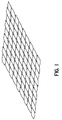
- the typical ballistic resistant woven materials presently employed involve a 2-dimensional weave as shown in Figure 1.
- yarns are woven at right angles to one another in directions referred to as warp and weft or fill.
- the woven material is typically a high modulus material such as fibers of aramid, glass, quartz, polyolefins, such as polypropylene and polyethylene, and various polyesters.
- certain liquid crystal polymers such as polybenzothiozole and polybenzoxizole have been suggested for such purposes. Spider silk has also been considered by some sources.
- the current 2-dimensional weaves are approximately 1.27mm(0.05 inches) to about 2.03mm(0.08 inches) thick and ballistic resistance is achieved by stacking together as many as thirty layers.
- the multi-layer panels are usually about 304.8mm(12 inches) wide by 12 inches long and can range up to any thickness, depending upon the level of protection desired. For instance, a typical thickness for a class 2A protection (9mm hand gun) is about 12.7mm(0.5 inches)
- the ballistic panels are then placed in strategic pockets in vests or jackets or similar articles of clothing to form body armor.
- the document US-A-5,104,726 discloses a multi-layer fabric for making reinforced plastic composites by impregnating the flexible fabric with resin and curing it, wherein both the warp yarns and the weft yarns rise and sink across the multilayer fabric structure following similar undulating paths over pairs of yarns of the opposite type.
- the fabric has interstices and is highly flexible favoring impregnation by a resin.
- the fabric is also indicated as having good resistance to penetration of ballistics when used as ballistics fabric.
- FIG 2 illustrates the usual situation where the projectile separates the warp and fill yarns before being stopped at some intermediate layer.
- the separation caused by an impinging projectile makes it necessary to stack together several layers of the woven material in order to provide any degree of ballistic resistance.
- the more layers required the heavier and less comfortable will be the particular piece of armor.
- continuing efforts are being made to provide fabrics exhibiting relatively light weight, while at the same time, exhibiting the desired degree of protection.
- comfort is sacrificed for adequate performance. Balancing performance and comfort without a prohibitively expensive product is a major problem that challenges those involved in the design of soft body armor.
- the present invention provides an article possessing improved ballistic resistance, while at the same time, being thinner than presently available articles exhibiting similar ballistic resistance. This in turn, makes it possible to provide relatively low weight ballistic resistant materials that nonetheless exhibit satisfactory resistance.
- the advantages achieved by the present invention are obtained by employing any suitable 3-dimensional weave configuration.
- the configuration of the present invention is such that the yarns impede the penetration of an impinging projectile to a far greater extent than that experienced in conventional 2-dimensional weave configurations of the prior art.
- the present invention is concerned with an article of manufacture that contains a plurality of yarns in the warp direction ( Figure 7).
- the thickness of the article is comprised of at least two planes of high modulus warp yarns. More than two planes of warp yarns constitutes construction of said article of various thicknesses.
- a yarn is woven such to bind together any plurality of warp yarns, the number of which are bound together to determine the desired thickness and construction of the article.
- a second fill yarn, located behind the first fill yarn is shifted over some specified increment in the width direction to bind together another plurality of warp yarns.
- a third fill yarn, located behind the second fill yarn is further incremently shifted over in the width direction and ties together another plurality of warp yarns. This shifting arrangement of yarns is continued throughout substantially the entire width of the warp direction thereby providing an interlocked article.
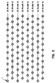
- Figure 3 shows a plurality of high modulus warp yarns (1), arranged as to comprise eight planes (2).
- the yarns (1) to facilitate an understanding of the present invention, are illustrated as being spaced apart but when woven, will be touching each other.
- Figure 3 illustrates an article comprising eight planes of warp yarns, the article can contain as few as two planes of warp yarns. The maximum number of warp planes is merely dictated by practical considerations, especially by the desired ballistic resistance for the particular article.
- the article contains a minimum of 2 planes of warp yarns, it can contain as many as desired for a required thickness but a preferable number is about 4-8 planes.
- a fill yarn is used to tie together a plurality of warp yarns, referred to as a bundle (3).
- Each bundle (3) typically contains at least 3 warp yarns.
- the maximum number of warp yarns per bundle is merely dictated by practical considerations.
- Figure 4 illustrates a bundle of 36 warp yarns.
- the high modulus fill yarns (4) can be any of the materials discussed previously that are employed for the high modulus warp yarns (1).
- the fill yarns (4) will be the same material as employed for the warp yarns (1), but do not have to be necessarily so.
- Figure 5 illustrates a second fill yarn (4') woven directly behind the first fill yarn (4) but shifted over by one warp yarn in plane 1 in the width direction.
- the second fill yarn (4') also ties together a bundle of 36 warp yarns.
- the angle (A) of fill yarns is dependent on the bundle size and is typically about 30 to about 120 degrees and, according to preferred aspects of the present invention is about 45 to about 75 degrees, and most preferably about 60 degrees. Of course, if desired, angle (A) need not be the same throughout the article, but can vary.
- Figure 6 illustrates a third fill yard (4'') woven directly behind the second fill yarn (4') but again shifted over by one warp yarn in plane 1 with respect to yarn (4') and two warp yarns in plane 1 with respect to yarn (4).
- the third fill yarn (4'') also ties together 36 warp yarns. This shifting arrangement of yarns continues throughout substantially the entire defined width of the article as illustrated in Figure 7.
- the warp yarns in plane 2 are offset from the yarns in both plane 1 and plane 3 by one yarn to the right in the width direction.
- the yarns in planes 1 and 3 are aligned with each other, as are the warp yarns in planes 5 and 7; whereas the warp yarns in planes 4, 6 and 8 are aligned with those in plane 2, but offset from the warp yarns in the odd numbered planes.
- This offset arrangement continues throughout substantially the entire defined height of the article, as illustrated in Figures 3-7.
- the warp yarns in one plane can be offset by more than one yarn from the warp yarns in an adjacent plane.
- each warp yarn plane be offset from each of its adjacent warp yarn planes. It has been found, however, that the preferred offset arrangement, as illustrated in Figures 3-7, provide the highest yarn packing configuration, which in turn, provides for the most effective results for stopping an impinging projectile, fragment, flechette or the like. Figures 5-7 also illustrate the most preferred angle A of about 60 degrees.
- the yarns employed are usually high elastic modulus yarns typically exhibiting a modulus of elasticity of at least about 10 4 MPa (megapascals) and more typically at least about 10 5 MPa.
- Examples of some typical high modulus yarns that can be employed pursuant to the present invention are aramid, glass fibers such as E-glass fibers and quartz, polyolefins such as polyethylene and polypropylene, polyesters, nylon, liquid crystal polymers such as polybentothiozole and polybenzoxizole, and silk.
- fiber blends can be used, if desired.
- yarns in the warp direction and/or yarns in the fill direction can all be of the same material or can be of two or more different materials in any arrangement.
- certain yarns in the warp direction could be of one type of material, while the other yarn in the warp direction could be of another material. It is preferred that the article obtained be flexible.
- the article typically at the end where the weaving is begun contains the various yarns in the warp and fill directions being looped around each other to maintain the integrity of the article.
- cut ends of the article can be fused together by heat and/or sealed off with epoxies or rubber cement to prevent fraying of the yarns.
- epoxies or rubber cement to prevent fraying of the yarns.
- the articles of the present invention can be constructed of two or more planes of warp yarns depending upon the desired ballistic resistance to be achieved by the particular article.
- the present invention employing a single thickness of the article can be used to replace a typical body armor employing about 25 layers of a 2-dimensional woven high modulus yarn, such as aramid (e.g. kevlar), to achieve the same or greater resistance and being significantly thinner than the combined 25 layers that would be employed in the prior art.
- aramid e.g. kevlar
- a single thickness of the high modulus yarns, woven pursuant to the present invention may provide class 3 protection (high powered rifles).
- Figures 8 and 9 show the results of a test performed on a article made of aramide (kevlar 29 having a modulus of at least about 1.5 x 10 5 MPa) yarn about 0.25 inches thick, having the interlock configuration pursuant to the present invention, wherein the thickness is 8 planes of warp yarns.
- the denier of the Kevlar 29 is about 3000.
- the deniers can be significantly higher or lower, depending upon the yarn chosen.
- three samples of the article were placed in cardboard boxes and backed by sand. The samples were shot by a 0.38 special revolver loaded with full metal jacket, 158 grain bullets from a distance of 15 feet. As shown in Figure 8, the bullet was effectively stopped by the article.
- Figure 9 shows that the bullet did not separate any of the yarns, thereby illustrating the advantages achieved by the present invention.
- the article can be employed for any lightweight armor application.
- the articles can be employed in preparing personal soft body armor, as well as armor for stationery and mobile objects, such as military vehicles, automobiles, planes, helicopters and satellites.
- the articles of the present invention When used for more typical soft body armor, such as vests, the articles of the present invention would be placed within particular strategic pockets in a vest or a jacket, as conventionally done with the prior art ballistic resistant woven materials.
- the articles of the present invention can be fabricated by standard industrial type looms.
Landscapes
- Engineering & Computer Science (AREA)
- Textile Engineering (AREA)
- Ceramic Engineering (AREA)
- General Engineering & Computer Science (AREA)
- Aiming, Guidance, Guns With A Light Source, Armor, Camouflage, And Targets (AREA)
- Woven Fabrics (AREA)
- Transition And Organic Metals Composition Catalysts For Addition Polymerization (AREA)
- Nonwoven Fabrics (AREA)
Claims (16)
- Industrieartikel, mit wenigstens zwei Ebenen (2), die mehrere Garne (1) enthalten, die sich in einer Kettrichtung erstrecken und sich in einer Füllrichtung in einer ersten Ebene befinden, ein erstes Füllgarn (4), das so gewebt ist, daß es mehrere (3) der Kettgarne bündelt; ein zweites Füllgarn (4'), das sich direkt hinter dem ersten Füllgarn (4) befindet und um ein spezifisches Inkrement in Kettrichtung gegenüber dem ersten Füllgarn (4) verschoben ist, um die gleiche Anzahl von Kettgarnen (1), wie vom ersten Füllgarn (4) gebündelt wird, zu bündeln; ein drittes Füllgarn (4''), das sich direkt hinter dem zweiten Füllgarn (4') befindet und um ein weiteres spezifisches Inkrement in Kettrichtung gegenüber dem zweiten Füllgarn (4') verschoben ist, um die gleiche Anzahl von Kettgarnen (1), wie durch das zweite Füllgarn (4') gebündelt wird, zu bündeln, wobei sich diese inkrementartig verschobene Anordnung von Füllgarnen (4, 4', 4'', ...), die die gleiche Mehrzahl von Kettgarnen bündelt, über die gesamte Kettabmessung fortsetzt, wodurch ein verzahnter dreidimensionaler Artikel geschaffen wird, und wobei der Winkel (A), der zwischen der Richtungsänderung jedes Füllgarns (4, 4', 4'', ...) erzeugt wird, im Bereich von 30 bis 120 Grad liegt.
- Industrieartikel nach Anspruch 1, wobei der Artikel so viele zueinander parallele Ebenen (2) aus Kettgarnen (1), wie für eine gewünschte Dicke erforderlich sind, enthält.
- Industrieartikel nach Anspruch 1, wobei der Artikel vier bis acht Ebenen (2) aus Kettgarnen (1) enthält.
- Industrieartikel nach Anspruch 1, wobei die Kettgarne einer Kettebene (2) in Breitenrichtung gegenüber den Kettgarnen einer daran angrenzenden Ebene (2) um die Dicke eines Garns versetzt sind und wobei zwei an dieselbe Kettebene angrenzende Ebenen aufeinander ausgerichtet sind.
- Industrieartikel nach einem der vorhergehenden Ansprüche, wobei jedes Füllgarn (4, 4', 4'', ...) seine Richtung ändert, wenn es eine Abschlußebene ausgehend von der anderen Abschlußebene der mehreren Ebenen (2) von Kettgarnen (1), die für eine gewünschte Dicke des dreidimensionalen Artikels gestapelt sind, erreicht.
- Industrieartikel nach Anspruch 1, wobei der Winkel (A) im Bereich von 45 bis 75 Grad liegt.
- Industrieartikel nach Anspruch 10, wobei der Winkel ungefähr 60 Grad beträgt.
- Industrieartikel nach Anspruch 1, wobei sämtliche Garne (1, 4) aus demselben Material bestehen.
- Industrieartikel nach Anspruch 1, wobei die Garne (1) in der Kettrichtung aus einem Material bestehen, das von demjenigen der Garne (4) in Füllrichtung verschieden ist.
- Industrieartikel nach Anspruch 1, wobei die Garne (1) in Kettrichtung aus unterschiedlichen Materialien bestehen.
- Industrieartikel nach Anspruch 1, wobei die Garne (4) in Füllrichtung aus unterschiedlichen Materialien bestehen.
- Industrieartikel nach Anspruch 1, wobei die Garne aus der Gruppe gewählt werden, die Garne aus Aramid, Glas, Quarz, Polyolefinen, Polyestern, Nylon, Polybenzothiozol, Polybenzoxizol, Seide und Gemischen hiervon umfaßt.
- Industrieartikel nach Anspruch 1, wobei sämtliche Garne (1, 4) aus Aramid bestehen.
- Industrieartikel nach Anspruch 1, der die Form einer Bewehrung hat.
- Industrieartikel nach Anspruch 14, der die Form einer Körperbewehrung hat.
- Industrieartikel nach Anspruch 14, der die Form einer Bewehrung für Fahrzeuge, Flugzeuge und Satelliten hat.
Applications Claiming Priority (5)
| Application Number | Priority Date | Filing Date | Title |
|---|---|---|---|
| US3138993A | 1993-03-12 | 1993-03-12 | |
| US31389 | 1993-03-12 | ||
| US202539 | 1994-02-28 | ||
| US08/202,539 US5456974A (en) | 1993-03-12 | 1994-02-28 | Ballistic resistant article comprising a three dimensional interlocking woven fabric |
| PCT/US1994/002686 WO1994020293A1 (en) | 1993-03-12 | 1994-03-11 | Ballistic resistant article |
Publications (3)
| Publication Number | Publication Date |
|---|---|
| EP0689501A1 EP0689501A1 (de) | 1996-01-03 |
| EP0689501A4 EP0689501A4 (de) | 1996-06-12 |
| EP0689501B1 true EP0689501B1 (de) | 2000-09-20 |
Family
ID=26707178
Family Applications (1)
| Application Number | Title | Priority Date | Filing Date |
|---|---|---|---|
| EP19940912217 Expired - Lifetime EP0689501B1 (de) | 1993-03-12 | 1994-03-11 | Schussfester gegenstand |
Country Status (6)
| Country | Link |
|---|---|
| US (1) | US5456974A (de) |
| EP (1) | EP0689501B1 (de) |
| AT (1) | ATE196445T1 (de) |
| DE (1) | DE69425962T2 (de) |
| ES (1) | ES2149870T3 (de) |
| WO (1) | WO1994020293A1 (de) |
Families Citing this family (15)
| Publication number | Priority date | Publication date | Assignee | Title |
|---|---|---|---|---|
| US5698480A (en) * | 1994-08-09 | 1997-12-16 | Hercules Incorporated | Textile structures containing linear low density polyethylene binder fibers |
| US6117546A (en) * | 1996-03-03 | 2000-09-12 | Hercules Incorporated | Yarns containing linear low density polyethylene fibers |
| GB2317622A (en) * | 1996-09-28 | 1998-04-01 | Wright M & Sons Ltd | Anti-ballistic fabric |
| FR2759096B1 (fr) * | 1997-02-04 | 1999-02-26 | Snecma | Texture multicouche liee pour materiaux composites structuraux |
| ES2292447T3 (es) | 1999-03-12 | 2008-03-16 | Simula, Inc. | Blindaje de tejido perfeccionado. |
| US6412261B1 (en) * | 2001-03-21 | 2002-07-02 | The Forman School | Method of reinforcing a fiber with spider silk |
| US6651543B2 (en) * | 2001-08-28 | 2003-11-25 | Andrew D. Park | Lightweight soft body-armor product |
| ATE387618T1 (de) * | 2003-12-05 | 2008-03-15 | Sgl Carbon Ag | Mehrschichtiges panzerschutzmaterial und verfahren zu seiner herstellung |
| WO2008016363A2 (en) * | 2005-08-10 | 2008-02-07 | E.I. Du Pont De Nemours And Company | Fiber network layers and flexible penetration resistant articles comprising same |
| WO2011038510A1 (en) * | 2009-10-02 | 2011-04-07 | Barrday Inc. | Woven multi-layer fabrics and methods of fabricating same |
| FR2965824B1 (fr) * | 2010-10-11 | 2013-11-15 | Snecma | Procede de fabrication d'une structure fibreuse metallique par tissage |
| CN104385612A (zh) * | 2014-10-08 | 2015-03-04 | 中国船舶重工集团公司第七二五研究所 | 一种纤维增强防弹复合材料及其制备方法 |
| US11435167B2 (en) | 2020-05-13 | 2022-09-06 | Jeffrey Wilson | Silk blend ballistic fabric |
| CN113388949A (zh) * | 2021-06-02 | 2021-09-14 | 深圳市汉唐世家服饰有限公司 | 防止划刺的穿透抑制型防刺布及其工艺 |
| US20250361658A1 (en) * | 2024-05-24 | 2025-11-27 | General Electric Company | Three-dimensional woven fabric for a composite component |
Family Cites Families (7)
| Publication number | Priority date | Publication date | Assignee | Title |
|---|---|---|---|---|
| US2816578A (en) * | 1953-06-17 | 1957-12-17 | Frieder | Ballistic cloth |
| US2899987A (en) * | 1955-05-19 | 1959-08-18 | Certificate of correction | |
| US2925098A (en) * | 1955-07-26 | 1960-02-16 | Gentex Corp | Ballistic fabric |
| FR2497839A1 (fr) * | 1981-01-12 | 1982-07-16 | Brochier Fils J | Tissu tridimensionnel pour le renforcement de materiaux stratifies et elements en forme obtenus a partir d'un tel tissu |
| JPH02173044A (ja) * | 1988-12-26 | 1990-07-04 | Toyobo Co Ltd | 繊維強化プラスチックおよびその補強材 |
| US5104726A (en) * | 1989-12-29 | 1992-04-14 | Woven Electronics Corporation | Woven fabric and process for reinforced structural composites |
| FR2682402B1 (fr) * | 1991-10-11 | 1994-01-14 | Propulsion Ste Europeenne | Bande de tissu tridimensionnel et procede de fabrication. |
-
1994
- 1994-02-28 US US08/202,539 patent/US5456974A/en not_active Expired - Lifetime
- 1994-03-11 AT AT94912217T patent/ATE196445T1/de not_active IP Right Cessation
- 1994-03-11 ES ES94912217T patent/ES2149870T3/es not_active Expired - Lifetime
- 1994-03-11 DE DE69425962T patent/DE69425962T2/de not_active Expired - Fee Related
- 1994-03-11 EP EP19940912217 patent/EP0689501B1/de not_active Expired - Lifetime
- 1994-03-11 WO PCT/US1994/002686 patent/WO1994020293A1/en not_active Ceased
Also Published As
| Publication number | Publication date |
|---|---|
| DE69425962T2 (de) | 2001-01-25 |
| EP0689501A4 (de) | 1996-06-12 |
| EP0689501A1 (de) | 1996-01-03 |
| US5456974A (en) | 1995-10-10 |
| WO1994020293A1 (en) | 1994-09-15 |
| ES2149870T3 (es) | 2000-11-16 |
| DE69425962D1 (de) | 2000-10-26 |
| ATE196445T1 (de) | 2000-10-15 |
Similar Documents
| Publication | Publication Date | Title |
|---|---|---|
| EP1144740B1 (de) | Penetrationsresistentes material mit einem gewebe mit hohem linearem dichteverhältnis zwischen zwei gruppen von garnen | |
| EP1241432B1 (de) | Penetrationsresistentes Material mit einem Gewebe mit hohem linearem Dichteverhältnis zwischen zwei Gruppen von Garnen | |
| EP0689501B1 (de) | Schussfester gegenstand | |
| US4681792A (en) | Multi-layered flexible fiber-containing articles | |
| US7820565B2 (en) | Densely woven quasi-unidirectional fabric for ballistic applications | |
| CA2500733C (en) | Bi-directional and multi-axial fabrics and fabric composites | |
| US5545455A (en) | Constructions having improved penetration resistance | |
| CA1198563A (en) | Ballistic-resistant article | |
| AU2002237321A1 (en) | Penetration-resistant material comprising fabric with high linear density ratio of two sets of threads | |
| AU2002247444B2 (en) | Ballistic resistant article | |
| CN103797169A (zh) | 用于改善柔性身体护甲弹道冲击性能的三轴向编织织物构造 | |
| CA2710526A1 (en) | Fabric architectures for improved ballistic impact performance | |
| KR20120027250A (ko) | 큰 필라멘트당 데니어 고성능 얀을 갖는 개선된 방탄 복합체 | |
| US7153790B2 (en) | Penetration-resistant material and articles made of the same | |
| KR20250081559A (ko) | 방폭원단 및 그 제조 방법 | |
| MXPA01007259A (en) | Penetration-resistant material comprising fabric with high linear density ratio of two sets of threads |
Legal Events
| Date | Code | Title | Description |
|---|---|---|---|
| PUAI | Public reference made under article 153(3) epc to a published international application that has entered the european phase |
Free format text: ORIGINAL CODE: 0009012 |
|
| 17P | Request for examination filed |
Effective date: 19950911 |
|
| AK | Designated contracting states |
Kind code of ref document: A1 Designated state(s): AT BE DE ES FR GB IT |
|
| A4 | Supplementary search report drawn up and despatched |
Effective date: 19960424 |
|
| AK | Designated contracting states |
Kind code of ref document: A4 Designated state(s): AT BE DE ES FR GB IT |
|
| 17Q | First examination report despatched |
Effective date: 19980730 |
|
| GRAG | Despatch of communication of intention to grant |
Free format text: ORIGINAL CODE: EPIDOS AGRA |
|
| GRAG | Despatch of communication of intention to grant |
Free format text: ORIGINAL CODE: EPIDOS AGRA |
|
| GRAH | Despatch of communication of intention to grant a patent |
Free format text: ORIGINAL CODE: EPIDOS IGRA |
|
| GRAH | Despatch of communication of intention to grant a patent |
Free format text: ORIGINAL CODE: EPIDOS IGRA |
|
| GRAA | (expected) grant |
Free format text: ORIGINAL CODE: 0009210 |
|
| AK | Designated contracting states |
Kind code of ref document: B1 Designated state(s): AT BE DE ES FR GB IT |
|
| PG25 | Lapsed in a contracting state [announced via postgrant information from national office to epo] |
Ref country code: BE Free format text: LAPSE BECAUSE OF FAILURE TO SUBMIT A TRANSLATION OF THE DESCRIPTION OR TO PAY THE FEE WITHIN THE PRESCRIBED TIME-LIMIT Effective date: 20000920 Ref country code: AT Free format text: LAPSE BECAUSE OF FAILURE TO SUBMIT A TRANSLATION OF THE DESCRIPTION OR TO PAY THE FEE WITHIN THE PRESCRIBED TIME-LIMIT Effective date: 20000920 |
|
| REF | Corresponds to: |
Ref document number: 196445 Country of ref document: AT Date of ref document: 20001015 Kind code of ref document: T |
|
| REF | Corresponds to: |
Ref document number: 69425962 Country of ref document: DE Date of ref document: 20001026 |
|
| REG | Reference to a national code |
Ref country code: ES Ref legal event code: FG2A Ref document number: 2149870 Country of ref document: ES Kind code of ref document: T3 |
|
| ITF | It: translation for a ep patent filed | ||
| ET | Fr: translation filed | ||
| PLBE | No opposition filed within time limit |
Free format text: ORIGINAL CODE: 0009261 |
|
| STAA | Information on the status of an ep patent application or granted ep patent |
Free format text: STATUS: NO OPPOSITION FILED WITHIN TIME LIMIT |
|
| 26N | No opposition filed | ||
| REG | Reference to a national code |
Ref country code: GB Ref legal event code: IF02 |
|
| PGFP | Annual fee paid to national office [announced via postgrant information from national office to epo] |
Ref country code: ES Payment date: 20030423 Year of fee payment: 10 |
|
| PGFP | Annual fee paid to national office [announced via postgrant information from national office to epo] |
Ref country code: FR Payment date: 20030425 Year of fee payment: 10 |
|
| PGFP | Annual fee paid to national office [announced via postgrant information from national office to epo] |
Ref country code: DE Payment date: 20030430 Year of fee payment: 10 |
|
| PGFP | Annual fee paid to national office [announced via postgrant information from national office to epo] |
Ref country code: GB Payment date: 20030501 Year of fee payment: 10 |
|
| PG25 | Lapsed in a contracting state [announced via postgrant information from national office to epo] |
Ref country code: GB Free format text: LAPSE BECAUSE OF NON-PAYMENT OF DUE FEES Effective date: 20040311 |
|
| PG25 | Lapsed in a contracting state [announced via postgrant information from national office to epo] |
Ref country code: ES Free format text: LAPSE BECAUSE OF NON-PAYMENT OF DUE FEES Effective date: 20040312 |
|
| PG25 | Lapsed in a contracting state [announced via postgrant information from national office to epo] |
Ref country code: DE Free format text: LAPSE BECAUSE OF NON-PAYMENT OF DUE FEES Effective date: 20041001 |
|
| GBPC | Gb: european patent ceased through non-payment of renewal fee |
Effective date: 20040311 |
|
| PG25 | Lapsed in a contracting state [announced via postgrant information from national office to epo] |
Ref country code: FR Free format text: LAPSE BECAUSE OF NON-PAYMENT OF DUE FEES Effective date: 20041130 |
|
| REG | Reference to a national code |
Ref country code: FR Ref legal event code: ST |
|
| PG25 | Lapsed in a contracting state [announced via postgrant information from national office to epo] |
Ref country code: IT Free format text: LAPSE BECAUSE OF NON-PAYMENT OF DUE FEES;WARNING: LAPSES OF ITALIAN PATENTS WITH EFFECTIVE DATE BEFORE 2007 MAY HAVE OCCURRED AT ANY TIME BEFORE 2007. THE CORRECT EFFECTIVE DATE MAY BE DIFFERENT FROM THE ONE RECORDED. Effective date: 20050311 |
|
| REG | Reference to a national code |
Ref country code: ES Ref legal event code: FD2A Effective date: 20040312 |