EP0689619B1 - Appareil et methode d'introduction de reactifs en phase gazeuse dans un reacteur de deposition en phase gazeuse par procede chimique (cvd) - Google Patents
Appareil et methode d'introduction de reactifs en phase gazeuse dans un reacteur de deposition en phase gazeuse par procede chimique (cvd) Download PDFInfo
- Publication number
- EP0689619B1 EP0689619B1 EP94913894A EP94913894A EP0689619B1 EP 0689619 B1 EP0689619 B1 EP 0689619B1 EP 94913894 A EP94913894 A EP 94913894A EP 94913894 A EP94913894 A EP 94913894A EP 0689619 B1 EP0689619 B1 EP 0689619B1
- Authority
- EP
- European Patent Office
- Prior art keywords
- liquid
- vaporization
- volume
- pumping
- piston
- Prior art date
- Legal status (The legal status is an assumption and is not a legal conclusion. Google has not performed a legal analysis and makes no representation as to the accuracy of the status listed.)
- Expired - Lifetime
Links
- 239000003153 chemical reaction reagent Substances 0.000 title claims abstract description 147
- 238000000034 method Methods 0.000 title claims abstract description 73
- 239000007788 liquid Substances 0.000 claims abstract description 236
- 230000008016 vaporization Effects 0.000 claims abstract description 191
- 238000009834 vaporization Methods 0.000 claims abstract description 179
- 238000004140 cleaning Methods 0.000 claims abstract description 87
- 238000005229 chemical vapour deposition Methods 0.000 claims abstract description 66
- 239000006200 vaporizer Substances 0.000 claims abstract description 60
- 239000007787 solid Substances 0.000 claims abstract description 37
- 230000008569 process Effects 0.000 claims abstract description 34
- 230000015572 biosynthetic process Effects 0.000 claims abstract description 12
- 238000005260 corrosion Methods 0.000 claims abstract description 8
- 230000007797 corrosion Effects 0.000 claims abstract description 8
- 230000002401 inhibitory effect Effects 0.000 claims abstract 5
- 238000005086 pumping Methods 0.000 claims description 105
- 239000012530 fluid Substances 0.000 claims description 99
- 239000007789 gas Substances 0.000 claims description 41
- 238000010926 purge Methods 0.000 claims description 25
- 239000000463 material Substances 0.000 claims description 23
- 239000002904 solvent Substances 0.000 claims description 21
- 239000012159 carrier gas Substances 0.000 claims description 20
- 238000000151 deposition Methods 0.000 claims description 20
- 230000008021 deposition Effects 0.000 claims description 19
- WYURNTSHIVDZCO-UHFFFAOYSA-N Tetrahydrofuran Chemical compound C1CCOC1 WYURNTSHIVDZCO-UHFFFAOYSA-N 0.000 claims description 14
- 238000007599 discharging Methods 0.000 claims description 14
- 238000007789 sealing Methods 0.000 claims description 14
- ZUHZGEOKBKGPSW-UHFFFAOYSA-N tetraglyme Chemical compound COCCOCCOCCOCCOC ZUHZGEOKBKGPSW-UHFFFAOYSA-N 0.000 claims description 13
- 238000009835 boiling Methods 0.000 claims description 12
- 239000000203 mixture Substances 0.000 claims description 12
- 230000000694 effects Effects 0.000 claims description 11
- 229910052751 metal Inorganic materials 0.000 claims description 8
- 239000002184 metal Substances 0.000 claims description 8
- YLQBMQCUIZJEEH-UHFFFAOYSA-N tetrahydrofuran Natural products C=1C=COC=1 YLQBMQCUIZJEEH-UHFFFAOYSA-N 0.000 claims description 7
- IJGRMHOSHXDMSA-UHFFFAOYSA-N Atomic nitrogen Chemical compound N#N IJGRMHOSHXDMSA-UHFFFAOYSA-N 0.000 claims description 6
- QVGXLLKOCUKJST-UHFFFAOYSA-N atomic oxygen Chemical compound [O] QVGXLLKOCUKJST-UHFFFAOYSA-N 0.000 claims description 6
- 239000001301 oxygen Substances 0.000 claims description 6
- 229910052760 oxygen Inorganic materials 0.000 claims description 6
- YFNKIDBQEZZDLK-UHFFFAOYSA-N triglyme Chemical compound COCCOCCOCCOC YFNKIDBQEZZDLK-UHFFFAOYSA-N 0.000 claims description 6
- KRHYYFGTRYWZRS-UHFFFAOYSA-N Fluorane Chemical compound F KRHYYFGTRYWZRS-UHFFFAOYSA-N 0.000 claims description 5
- 238000010438 heat treatment Methods 0.000 claims description 5
- 229920000768 polyamine Polymers 0.000 claims description 5
- XKRFYHLGVUSROY-UHFFFAOYSA-N Argon Chemical compound [Ar] XKRFYHLGVUSROY-UHFFFAOYSA-N 0.000 claims description 4
- 238000004891 communication Methods 0.000 claims description 4
- 229920000570 polyether Polymers 0.000 claims description 4
- VILCJCGEZXAXTO-UHFFFAOYSA-N 2,2,2-tetramine Chemical compound NCCNCCNCCN VILCJCGEZXAXTO-UHFFFAOYSA-N 0.000 claims description 3
- 239000006227 byproduct Substances 0.000 claims description 3
- 229910052757 nitrogen Inorganic materials 0.000 claims description 3
- FAGUFWYHJQFNRV-UHFFFAOYSA-N tetraethylenepentamine Chemical compound NCCNCCNCCNCCN FAGUFWYHJQFNRV-UHFFFAOYSA-N 0.000 claims description 3
- UFHFLCQGNIYNRP-UHFFFAOYSA-N Hydrogen Chemical compound [H][H] UFHFLCQGNIYNRP-UHFFFAOYSA-N 0.000 claims description 2
- 229910052786 argon Inorganic materials 0.000 claims description 2
- 239000001307 helium Substances 0.000 claims description 2
- 229910052734 helium Inorganic materials 0.000 claims description 2
- SWQJXJOGLNCZEY-UHFFFAOYSA-N helium atom Chemical compound [He] SWQJXJOGLNCZEY-UHFFFAOYSA-N 0.000 claims description 2
- 239000001257 hydrogen Substances 0.000 claims description 2
- 229910052739 hydrogen Inorganic materials 0.000 claims description 2
- 239000007769 metal material Substances 0.000 claims description 2
- 239000003960 organic solvent Substances 0.000 claims description 2
- SBZXBUIDTXKZTM-UHFFFAOYSA-N diglyme Chemical compound COCCOCCOC SBZXBUIDTXKZTM-UHFFFAOYSA-N 0.000 claims 2
- 230000005764 inhibitory process Effects 0.000 claims 2
- 150000001298 alcohols Chemical class 0.000 claims 1
- 150000004982 aromatic amines Chemical class 0.000 claims 1
- 229910010293 ceramic material Inorganic materials 0.000 claims 1
- 150000002170 ethers Chemical class 0.000 claims 1
- 229910000040 hydrogen fluoride Inorganic materials 0.000 claims 1
- 238000000354 decomposition reaction Methods 0.000 abstract description 23
- 230000002028 premature Effects 0.000 abstract description 4
- 230000009931 harmful effect Effects 0.000 abstract 1
- 238000006864 oxidative decomposition reaction Methods 0.000 abstract 1
- 239000012265 solid product Substances 0.000 abstract 1
- KFZMGEQAYNKOFK-UHFFFAOYSA-N Isopropanol Chemical compound CC(C)O KFZMGEQAYNKOFK-UHFFFAOYSA-N 0.000 description 24
- 239000002243 precursor Substances 0.000 description 22
- 239000010408 film Substances 0.000 description 19
- 150000001875 compounds Chemical class 0.000 description 15
- 239000002245 particle Substances 0.000 description 15
- 239000000047 product Substances 0.000 description 15
- 230000009977 dual effect Effects 0.000 description 11
- BPUBBGLMJRNUCC-UHFFFAOYSA-N oxygen(2-);tantalum(5+) Chemical compound [O-2].[O-2].[O-2].[O-2].[O-2].[Ta+5].[Ta+5] BPUBBGLMJRNUCC-UHFFFAOYSA-N 0.000 description 9
- 239000000126 substance Substances 0.000 description 9
- 229910001936 tantalum oxide Inorganic materials 0.000 description 9
- 239000010936 titanium Substances 0.000 description 9
- RTZKZFJDLAIYFH-UHFFFAOYSA-N Diethyl ether Chemical compound CCOCC RTZKZFJDLAIYFH-UHFFFAOYSA-N 0.000 description 8
- QGZKDVFQNNGYKY-UHFFFAOYSA-N Ammonia Chemical compound N QGZKDVFQNNGYKY-UHFFFAOYSA-N 0.000 description 7
- 238000006243 chemical reaction Methods 0.000 description 7
- 238000000576 coating method Methods 0.000 description 7
- 239000010410 layer Substances 0.000 description 7
- 239000000758 substrate Substances 0.000 description 7
- NGCRLFIYVFOUMZ-UHFFFAOYSA-N 2,3-dichloroquinoxaline-6-carbonyl chloride Chemical compound N1=C(Cl)C(Cl)=NC2=CC(C(=O)Cl)=CC=C21 NGCRLFIYVFOUMZ-UHFFFAOYSA-N 0.000 description 6
- 229910052788 barium Inorganic materials 0.000 description 6
- DSAJWYNOEDNPEQ-UHFFFAOYSA-N barium atom Chemical compound [Ba] DSAJWYNOEDNPEQ-UHFFFAOYSA-N 0.000 description 6
- 229910002113 barium titanate Inorganic materials 0.000 description 6
- 229910052719 titanium Inorganic materials 0.000 description 6
- JRPBQTZRNDNNOP-UHFFFAOYSA-N barium titanate Chemical compound [Ba+2].[Ba+2].[O-][Ti]([O-])([O-])[O-] JRPBQTZRNDNNOP-UHFFFAOYSA-N 0.000 description 5
- 230000008901 benefit Effects 0.000 description 5
- 230000015556 catabolic process Effects 0.000 description 5
- 239000011248 coating agent Substances 0.000 description 5
- 239000011159 matrix material Substances 0.000 description 5
- ROSDSFDQCJNGOL-UHFFFAOYSA-N Dimethylamine Chemical compound CNC ROSDSFDQCJNGOL-UHFFFAOYSA-N 0.000 description 4
- LFQSCWFLJHTTHZ-UHFFFAOYSA-N Ethanol Chemical compound CCO LFQSCWFLJHTTHZ-UHFFFAOYSA-N 0.000 description 4
- RTAQQCXQSZGOHL-UHFFFAOYSA-N Titanium Chemical compound [Ti] RTAQQCXQSZGOHL-UHFFFAOYSA-N 0.000 description 4
- 238000013459 approach Methods 0.000 description 4
- 239000003990 capacitor Substances 0.000 description 4
- 238000010276 construction Methods 0.000 description 4
- 238000006731 degradation reaction Methods 0.000 description 4
- 238000011065 in-situ storage Methods 0.000 description 4
- 239000011261 inert gas Substances 0.000 description 4
- 238000012423 maintenance Methods 0.000 description 4
- 230000007246 mechanism Effects 0.000 description 4
- 238000004377 microelectronic Methods 0.000 description 4
- 239000012071 phase Substances 0.000 description 4
- 239000011819 refractory material Substances 0.000 description 4
- PBCFLUZVCVVTBY-UHFFFAOYSA-N tantalum pentoxide Inorganic materials O=[Ta](=O)O[Ta](=O)=O PBCFLUZVCVVTBY-UHFFFAOYSA-N 0.000 description 4
- 239000010409 thin film Substances 0.000 description 4
- 239000012808 vapor phase Substances 0.000 description 4
- KXDHJXZQYSOELW-UHFFFAOYSA-M Carbamate Chemical compound NC([O-])=O KXDHJXZQYSOELW-UHFFFAOYSA-M 0.000 description 3
- ATJFFYVFTNAWJD-UHFFFAOYSA-N Tin Chemical compound [Sn] ATJFFYVFTNAWJD-UHFFFAOYSA-N 0.000 description 3
- NRTOMJZYCJJWKI-UHFFFAOYSA-N Titanium nitride Chemical group [Ti]#N NRTOMJZYCJJWKI-UHFFFAOYSA-N 0.000 description 3
- 239000002253 acid Substances 0.000 description 3
- 229910021529 ammonia Inorganic materials 0.000 description 3
- 238000011109 contamination Methods 0.000 description 3
- 238000009826 distribution Methods 0.000 description 3
- 238000005516 engineering process Methods 0.000 description 3
- 230000006870 function Effects 0.000 description 3
- 230000005484 gravity Effects 0.000 description 3
- 239000012535 impurity Substances 0.000 description 3
- 238000004519 manufacturing process Methods 0.000 description 3
- VLKZOEOYAKHREP-UHFFFAOYSA-N n-Hexane Chemical compound CCCCCC VLKZOEOYAKHREP-UHFFFAOYSA-N 0.000 description 3
- SOQBVABWOPYFQZ-UHFFFAOYSA-N oxygen(2-);titanium(4+) Chemical class [O-2].[O-2].[Ti+4] SOQBVABWOPYFQZ-UHFFFAOYSA-N 0.000 description 3
- 238000009428 plumbing Methods 0.000 description 3
- 238000000859 sublimation Methods 0.000 description 3
- 230000008022 sublimation Effects 0.000 description 3
- HSXKFDGTKKAEHL-UHFFFAOYSA-N tantalum(v) ethoxide Chemical compound [Ta+5].CC[O-].CC[O-].CC[O-].CC[O-].CC[O-] HSXKFDGTKKAEHL-UHFFFAOYSA-N 0.000 description 3
- OGIDPMRJRNCKJF-UHFFFAOYSA-N titanium oxide Inorganic materials [Ti]=O OGIDPMRJRNCKJF-UHFFFAOYSA-N 0.000 description 3
- XLYOFNOQVPJJNP-UHFFFAOYSA-N water Substances O XLYOFNOQVPJJNP-UHFFFAOYSA-N 0.000 description 3
- 239000004721 Polyphenylene oxide Substances 0.000 description 2
- BOTDANWDWHJENH-UHFFFAOYSA-N Tetraethyl orthosilicate Chemical compound CCO[Si](OCC)(OCC)OCC BOTDANWDWHJENH-UHFFFAOYSA-N 0.000 description 2
- 238000009825 accumulation Methods 0.000 description 2
- 229910052784 alkaline earth metal Inorganic materials 0.000 description 2
- -1 alkoxide compounds Chemical class 0.000 description 2
- 229910052782 aluminium Inorganic materials 0.000 description 2
- XAGFODPZIPBFFR-UHFFFAOYSA-N aluminium Chemical compound [Al] XAGFODPZIPBFFR-UHFFFAOYSA-N 0.000 description 2
- 239000000470 constituent Substances 0.000 description 2
- 238000004090 dissolution Methods 0.000 description 2
- 238000011010 flushing procedure Methods 0.000 description 2
- 150000004679 hydroxides Chemical class 0.000 description 2
- 238000012986 modification Methods 0.000 description 2
- 230000004048 modification Effects 0.000 description 2
- 230000009972 noncorrosive effect Effects 0.000 description 2
- 238000012856 packing Methods 0.000 description 2
- NFHFRUOZVGFOOS-UHFFFAOYSA-N palladium;triphenylphosphane Chemical class [Pd].C1=CC=CC=C1P(C=1C=CC=CC=1)C1=CC=CC=C1.C1=CC=CC=C1P(C=1C=CC=CC=1)C1=CC=CC=C1.C1=CC=CC=C1P(C=1C=CC=CC=1)C1=CC=CC=C1.C1=CC=CC=C1P(C=1C=CC=CC=1)C1=CC=CC=C1 NFHFRUOZVGFOOS-UHFFFAOYSA-N 0.000 description 2
- 239000000376 reactant Substances 0.000 description 2
- 230000008929 regeneration Effects 0.000 description 2
- 238000011069 regeneration method Methods 0.000 description 2
- 238000003860 storage Methods 0.000 description 2
- 229910052712 strontium Inorganic materials 0.000 description 2
- MNWRORMXBIWXCI-UHFFFAOYSA-N tetrakis(dimethylamido)titanium Chemical compound CN(C)[Ti](N(C)C)(N(C)C)N(C)C MNWRORMXBIWXCI-UHFFFAOYSA-N 0.000 description 2
- 231100000331 toxic Toxicity 0.000 description 2
- 230000002588 toxic effect Effects 0.000 description 2
- GETQZCLCWQTVFV-UHFFFAOYSA-N trimethylamine Chemical compound CN(C)C GETQZCLCWQTVFV-UHFFFAOYSA-N 0.000 description 2
- BGGIUGXMWNKMCP-UHFFFAOYSA-N 2-methylpropan-2-olate;zirconium(4+) Chemical compound CC(C)(C)O[Zr](OC(C)(C)C)(OC(C)(C)C)OC(C)(C)C BGGIUGXMWNKMCP-UHFFFAOYSA-N 0.000 description 1
- 229910015846 BaxSr1-xTiO3 Inorganic materials 0.000 description 1
- OYPRJOBELJOOCE-UHFFFAOYSA-N Calcium Chemical compound [Ca] OYPRJOBELJOOCE-UHFFFAOYSA-N 0.000 description 1
- 229910019695 Nb2O6 Inorganic materials 0.000 description 1
- XUIMIQQOPSSXEZ-UHFFFAOYSA-N Silicon Chemical compound [Si] XUIMIQQOPSSXEZ-UHFFFAOYSA-N 0.000 description 1
- 229920006362 Teflon® Polymers 0.000 description 1
- 229910010252 TiO3 Inorganic materials 0.000 description 1
- XSQUKJJJFZCRTK-UHFFFAOYSA-N Urea Chemical compound NC(N)=O XSQUKJJJFZCRTK-UHFFFAOYSA-N 0.000 description 1
- QCWXUUIWCKQGHC-UHFFFAOYSA-N Zirconium Chemical compound [Zr] QCWXUUIWCKQGHC-UHFFFAOYSA-N 0.000 description 1
- 230000009471 action Effects 0.000 description 1
- 229910000086 alane Inorganic materials 0.000 description 1
- AZDRQVAHHNSJOQ-UHFFFAOYSA-N alumane Chemical compound [AlH3] AZDRQVAHHNSJOQ-UHFFFAOYSA-N 0.000 description 1
- 229910001632 barium fluoride Inorganic materials 0.000 description 1
- 229910052454 barium strontium titanate Inorganic materials 0.000 description 1
- 230000004888 barrier function Effects 0.000 description 1
- 229910052791 calcium Inorganic materials 0.000 description 1
- 239000011575 calcium Substances 0.000 description 1
- WUKWITHWXAAZEY-UHFFFAOYSA-L calcium difluoride Chemical compound [F-].[F-].[Ca+2] WUKWITHWXAAZEY-UHFFFAOYSA-L 0.000 description 1
- 229910001634 calcium fluoride Inorganic materials 0.000 description 1
- 239000004202 carbamide Substances 0.000 description 1
- 239000000919 ceramic Substances 0.000 description 1
- 230000008859 change Effects 0.000 description 1
- 238000009833 condensation Methods 0.000 description 1
- 230000005494 condensation Effects 0.000 description 1
- 239000000356 contaminant Substances 0.000 description 1
- 238000010924 continuous production Methods 0.000 description 1
- 230000001276 controlling effect Effects 0.000 description 1
- 238000007796 conventional method Methods 0.000 description 1
- 230000008878 coupling Effects 0.000 description 1
- 238000010168 coupling process Methods 0.000 description 1
- 238000005859 coupling reaction Methods 0.000 description 1
- 239000013078 crystal Substances 0.000 description 1
- 230000007812 deficiency Effects 0.000 description 1
- 230000002939 deleterious effect Effects 0.000 description 1
- 230000001419 dependent effect Effects 0.000 description 1
- 238000005137 deposition process Methods 0.000 description 1
- 230000001066 destructive effect Effects 0.000 description 1
- 230000006866 deterioration Effects 0.000 description 1
- 230000002542 deteriorative effect Effects 0.000 description 1
- 238000009792 diffusion process Methods 0.000 description 1
- 238000006073 displacement reaction Methods 0.000 description 1
- 238000001035 drying Methods 0.000 description 1
- 230000005684 electric field Effects 0.000 description 1
- 230000002708 enhancing effect Effects 0.000 description 1
- 238000002474 experimental method Methods 0.000 description 1
- 150000002222 fluorine compounds Chemical class 0.000 description 1
- 238000010574 gas phase reaction Methods 0.000 description 1
- 229910052735 hafnium Inorganic materials 0.000 description 1
- VBJZVLUMGGDVMO-UHFFFAOYSA-N hafnium atom Chemical compound [Hf] VBJZVLUMGGDVMO-UHFFFAOYSA-N 0.000 description 1
- 231100001261 hazardous Toxicity 0.000 description 1
- 239000002920 hazardous waste Substances 0.000 description 1
- 230000006872 improvement Effects 0.000 description 1
- 239000012212 insulator Substances 0.000 description 1
- 230000010354 integration Effects 0.000 description 1
- 238000005304 joining Methods 0.000 description 1
- 229910052743 krypton Inorganic materials 0.000 description 1
- DNNSSWSSYDEUBZ-UHFFFAOYSA-N krypton atom Chemical compound [Kr] DNNSSWSSYDEUBZ-UHFFFAOYSA-N 0.000 description 1
- 229910052451 lead zirconate titanate Inorganic materials 0.000 description 1
- HFGPZNIAWCZYJU-UHFFFAOYSA-N lead zirconate titanate Chemical compound [O-2].[O-2].[O-2].[O-2].[O-2].[Ti+4].[Zr+4].[Pb+2] HFGPZNIAWCZYJU-UHFFFAOYSA-N 0.000 description 1
- 239000011344 liquid material Substances 0.000 description 1
- 239000012705 liquid precursor Substances 0.000 description 1
- 238000002488 metal-organic chemical vapour deposition Methods 0.000 description 1
- 238000002156 mixing Methods 0.000 description 1
- 229910052754 neon Inorganic materials 0.000 description 1
- GKAOGPIIYCISHV-UHFFFAOYSA-N neon atom Chemical compound [Ne] GKAOGPIIYCISHV-UHFFFAOYSA-N 0.000 description 1
- 239000003921 oil Substances 0.000 description 1
- 239000013307 optical fiber Substances 0.000 description 1
- 238000005457 optimization Methods 0.000 description 1
- 150000002902 organometallic compounds Chemical class 0.000 description 1
- 230000037361 pathway Effects 0.000 description 1
- 230000005855 radiation Effects 0.000 description 1
- 239000002516 radical scavenger Substances 0.000 description 1
- 239000011541 reaction mixture Substances 0.000 description 1
- 230000003134 recirculating effect Effects 0.000 description 1
- 230000001105 regulatory effect Effects 0.000 description 1
- 230000008439 repair process Effects 0.000 description 1
- 230000004044 response Effects 0.000 description 1
- 230000002000 scavenging effect Effects 0.000 description 1
- 239000004065 semiconductor Substances 0.000 description 1
- 229910052710 silicon Inorganic materials 0.000 description 1
- 239000010703 silicon Substances 0.000 description 1
- 239000011343 solid material Substances 0.000 description 1
- 125000006850 spacer group Chemical group 0.000 description 1
- 229910001220 stainless steel Inorganic materials 0.000 description 1
- 239000010935 stainless steel Substances 0.000 description 1
- CIOAGBVUUVVLOB-UHFFFAOYSA-N strontium atom Chemical compound [Sr] CIOAGBVUUVVLOB-UHFFFAOYSA-N 0.000 description 1
- 229910001637 strontium fluoride Inorganic materials 0.000 description 1
- FVRNDBHWWSPNOM-UHFFFAOYSA-L strontium fluoride Chemical compound [F-].[F-].[Sr+2] FVRNDBHWWSPNOM-UHFFFAOYSA-L 0.000 description 1
- 239000002887 superconductor Substances 0.000 description 1
- 238000003786 synthesis reaction Methods 0.000 description 1
- 229910052715 tantalum Inorganic materials 0.000 description 1
- GUVRBAGPIYLISA-UHFFFAOYSA-N tantalum atom Chemical compound [Ta] GUVRBAGPIYLISA-UHFFFAOYSA-N 0.000 description 1
- 230000002123 temporal effect Effects 0.000 description 1
- 150000003476 thallium compounds Chemical class 0.000 description 1
- 238000005979 thermal decomposition reaction Methods 0.000 description 1
- 150000003608 titanium Chemical class 0.000 description 1
- 231100000167 toxic agent Toxicity 0.000 description 1
- 239000003440 toxic substance Substances 0.000 description 1
- 229910052723 transition metal Inorganic materials 0.000 description 1
- 150000003624 transition metals Chemical class 0.000 description 1
- 230000001960 triggered effect Effects 0.000 description 1
- MCULRUJILOGHCJ-UHFFFAOYSA-N triisobutylaluminium Chemical compound CC(C)C[Al](CC(C)C)CC(C)C MCULRUJILOGHCJ-UHFFFAOYSA-N 0.000 description 1
- XCZXGTMEAKBVPV-UHFFFAOYSA-N trimethylgallium Chemical compound C[Ga](C)C XCZXGTMEAKBVPV-UHFFFAOYSA-N 0.000 description 1
- 238000002604 ultrasonography Methods 0.000 description 1
- 238000005406 washing Methods 0.000 description 1
- 239000002912 waste gas Substances 0.000 description 1
- 229910052726 zirconium Inorganic materials 0.000 description 1
Images

Classifications
-
- C—CHEMISTRY; METALLURGY
- C23—COATING METALLIC MATERIAL; COATING MATERIAL WITH METALLIC MATERIAL; CHEMICAL SURFACE TREATMENT; DIFFUSION TREATMENT OF METALLIC MATERIAL; COATING BY VACUUM EVAPORATION, BY SPUTTERING, BY ION IMPLANTATION OR BY CHEMICAL VAPOUR DEPOSITION, IN GENERAL; INHIBITING CORROSION OF METALLIC MATERIAL OR INCRUSTATION IN GENERAL
- C23C—COATING METALLIC MATERIAL; COATING MATERIAL WITH METALLIC MATERIAL; SURFACE TREATMENT OF METALLIC MATERIAL BY DIFFUSION INTO THE SURFACE, BY CHEMICAL CONVERSION OR SUBSTITUTION; COATING BY VACUUM EVAPORATION, BY SPUTTERING, BY ION IMPLANTATION OR BY CHEMICAL VAPOUR DEPOSITION, IN GENERAL
- C23C16/00—Chemical coating by decomposition of gaseous compounds, without leaving reaction products of surface material in the coating, i.e. chemical vapour deposition [CVD] processes
- C23C16/44—Chemical coating by decomposition of gaseous compounds, without leaving reaction products of surface material in the coating, i.e. chemical vapour deposition [CVD] processes characterised by the method of coating
- C23C16/448—Chemical coating by decomposition of gaseous compounds, without leaving reaction products of surface material in the coating, i.e. chemical vapour deposition [CVD] processes characterised by the method of coating characterised by the method used for generating reactive gas streams, e.g. by evaporation or sublimation of precursor materials
- C23C16/4481—Chemical coating by decomposition of gaseous compounds, without leaving reaction products of surface material in the coating, i.e. chemical vapour deposition [CVD] processes characterised by the method of coating characterised by the method used for generating reactive gas streams, e.g. by evaporation or sublimation of precursor materials by evaporation using carrier gas in contact with the source material
- C23C16/4483—Chemical coating by decomposition of gaseous compounds, without leaving reaction products of surface material in the coating, i.e. chemical vapour deposition [CVD] processes characterised by the method of coating characterised by the method used for generating reactive gas streams, e.g. by evaporation or sublimation of precursor materials by evaporation using carrier gas in contact with the source material using a porous body
-
- B—PERFORMING OPERATIONS; TRANSPORTING
- B01—PHYSICAL OR CHEMICAL PROCESSES OR APPARATUS IN GENERAL
- B01F—MIXING, e.g. DISSOLVING, EMULSIFYING OR DISPERSING
- B01F23/00—Mixing according to the phases to be mixed, e.g. dispersing or emulsifying
- B01F23/10—Mixing gases with gases
- B01F23/12—Mixing gases with gases with vaporisation of a liquid
-
- C—CHEMISTRY; METALLURGY
- C23—COATING METALLIC MATERIAL; COATING MATERIAL WITH METALLIC MATERIAL; CHEMICAL SURFACE TREATMENT; DIFFUSION TREATMENT OF METALLIC MATERIAL; COATING BY VACUUM EVAPORATION, BY SPUTTERING, BY ION IMPLANTATION OR BY CHEMICAL VAPOUR DEPOSITION, IN GENERAL; INHIBITING CORROSION OF METALLIC MATERIAL OR INCRUSTATION IN GENERAL
- C23C—COATING METALLIC MATERIAL; COATING MATERIAL WITH METALLIC MATERIAL; SURFACE TREATMENT OF METALLIC MATERIAL BY DIFFUSION INTO THE SURFACE, BY CHEMICAL CONVERSION OR SUBSTITUTION; COATING BY VACUUM EVAPORATION, BY SPUTTERING, BY ION IMPLANTATION OR BY CHEMICAL VAPOUR DEPOSITION, IN GENERAL
- C23C16/00—Chemical coating by decomposition of gaseous compounds, without leaving reaction products of surface material in the coating, i.e. chemical vapour deposition [CVD] processes
- C23C16/22—Chemical coating by decomposition of gaseous compounds, without leaving reaction products of surface material in the coating, i.e. chemical vapour deposition [CVD] processes characterised by the deposition of inorganic material, other than metallic material
- C23C16/30—Deposition of compounds, mixtures or solid solutions, e.g. borides, carbides, nitrides
- C23C16/40—Oxides
-
- C—CHEMISTRY; METALLURGY
- C23—COATING METALLIC MATERIAL; COATING MATERIAL WITH METALLIC MATERIAL; CHEMICAL SURFACE TREATMENT; DIFFUSION TREATMENT OF METALLIC MATERIAL; COATING BY VACUUM EVAPORATION, BY SPUTTERING, BY ION IMPLANTATION OR BY CHEMICAL VAPOUR DEPOSITION, IN GENERAL; INHIBITING CORROSION OF METALLIC MATERIAL OR INCRUSTATION IN GENERAL
- C23C—COATING METALLIC MATERIAL; COATING MATERIAL WITH METALLIC MATERIAL; SURFACE TREATMENT OF METALLIC MATERIAL BY DIFFUSION INTO THE SURFACE, BY CHEMICAL CONVERSION OR SUBSTITUTION; COATING BY VACUUM EVAPORATION, BY SPUTTERING, BY ION IMPLANTATION OR BY CHEMICAL VAPOUR DEPOSITION, IN GENERAL
- C23C16/00—Chemical coating by decomposition of gaseous compounds, without leaving reaction products of surface material in the coating, i.e. chemical vapour deposition [CVD] processes
- C23C16/22—Chemical coating by decomposition of gaseous compounds, without leaving reaction products of surface material in the coating, i.e. chemical vapour deposition [CVD] processes characterised by the deposition of inorganic material, other than metallic material
- C23C16/30—Deposition of compounds, mixtures or solid solutions, e.g. borides, carbides, nitrides
- C23C16/40—Oxides
- C23C16/408—Oxides of copper or solid solutions thereof
-
- C—CHEMISTRY; METALLURGY
- C23—COATING METALLIC MATERIAL; COATING MATERIAL WITH METALLIC MATERIAL; CHEMICAL SURFACE TREATMENT; DIFFUSION TREATMENT OF METALLIC MATERIAL; COATING BY VACUUM EVAPORATION, BY SPUTTERING, BY ION IMPLANTATION OR BY CHEMICAL VAPOUR DEPOSITION, IN GENERAL; INHIBITING CORROSION OF METALLIC MATERIAL OR INCRUSTATION IN GENERAL
- C23C—COATING METALLIC MATERIAL; COATING MATERIAL WITH METALLIC MATERIAL; SURFACE TREATMENT OF METALLIC MATERIAL BY DIFFUSION INTO THE SURFACE, BY CHEMICAL CONVERSION OR SUBSTITUTION; COATING BY VACUUM EVAPORATION, BY SPUTTERING, BY ION IMPLANTATION OR BY CHEMICAL VAPOUR DEPOSITION, IN GENERAL
- C23C16/00—Chemical coating by decomposition of gaseous compounds, without leaving reaction products of surface material in the coating, i.e. chemical vapour deposition [CVD] processes
- C23C16/22—Chemical coating by decomposition of gaseous compounds, without leaving reaction products of surface material in the coating, i.e. chemical vapour deposition [CVD] processes characterised by the deposition of inorganic material, other than metallic material
- C23C16/30—Deposition of compounds, mixtures or solid solutions, e.g. borides, carbides, nitrides
- C23C16/40—Oxides
- C23C16/409—Oxides of the type ABO3 with A representing alkali, alkaline earth metal or lead and B representing a refractory metal, nickel, scandium or a lanthanide
-
- C—CHEMISTRY; METALLURGY
- C23—COATING METALLIC MATERIAL; COATING MATERIAL WITH METALLIC MATERIAL; CHEMICAL SURFACE TREATMENT; DIFFUSION TREATMENT OF METALLIC MATERIAL; COATING BY VACUUM EVAPORATION, BY SPUTTERING, BY ION IMPLANTATION OR BY CHEMICAL VAPOUR DEPOSITION, IN GENERAL; INHIBITING CORROSION OF METALLIC MATERIAL OR INCRUSTATION IN GENERAL
- C23C—COATING METALLIC MATERIAL; COATING MATERIAL WITH METALLIC MATERIAL; SURFACE TREATMENT OF METALLIC MATERIAL BY DIFFUSION INTO THE SURFACE, BY CHEMICAL CONVERSION OR SUBSTITUTION; COATING BY VACUUM EVAPORATION, BY SPUTTERING, BY ION IMPLANTATION OR BY CHEMICAL VAPOUR DEPOSITION, IN GENERAL
- C23C16/00—Chemical coating by decomposition of gaseous compounds, without leaving reaction products of surface material in the coating, i.e. chemical vapour deposition [CVD] processes
- C23C16/44—Chemical coating by decomposition of gaseous compounds, without leaving reaction products of surface material in the coating, i.e. chemical vapour deposition [CVD] processes characterised by the method of coating
- C23C16/4401—Means for minimising impurities, e.g. dust, moisture or residual gas, in the reaction chamber
- C23C16/4407—Cleaning of reactor or reactor parts by using wet or mechanical methods
-
- C—CHEMISTRY; METALLURGY
- C23—COATING METALLIC MATERIAL; COATING MATERIAL WITH METALLIC MATERIAL; CHEMICAL SURFACE TREATMENT; DIFFUSION TREATMENT OF METALLIC MATERIAL; COATING BY VACUUM EVAPORATION, BY SPUTTERING, BY ION IMPLANTATION OR BY CHEMICAL VAPOUR DEPOSITION, IN GENERAL; INHIBITING CORROSION OF METALLIC MATERIAL OR INCRUSTATION IN GENERAL
- C23C—COATING METALLIC MATERIAL; COATING MATERIAL WITH METALLIC MATERIAL; SURFACE TREATMENT OF METALLIC MATERIAL BY DIFFUSION INTO THE SURFACE, BY CHEMICAL CONVERSION OR SUBSTITUTION; COATING BY VACUUM EVAPORATION, BY SPUTTERING, BY ION IMPLANTATION OR BY CHEMICAL VAPOUR DEPOSITION, IN GENERAL
- C23C16/00—Chemical coating by decomposition of gaseous compounds, without leaving reaction products of surface material in the coating, i.e. chemical vapour deposition [CVD] processes
- C23C16/44—Chemical coating by decomposition of gaseous compounds, without leaving reaction products of surface material in the coating, i.e. chemical vapour deposition [CVD] processes characterised by the method of coating
- C23C16/448—Chemical coating by decomposition of gaseous compounds, without leaving reaction products of surface material in the coating, i.e. chemical vapour deposition [CVD] processes characterised by the method of coating characterised by the method used for generating reactive gas streams, e.g. by evaporation or sublimation of precursor materials
-
- C—CHEMISTRY; METALLURGY
- C23—COATING METALLIC MATERIAL; COATING MATERIAL WITH METALLIC MATERIAL; CHEMICAL SURFACE TREATMENT; DIFFUSION TREATMENT OF METALLIC MATERIAL; COATING BY VACUUM EVAPORATION, BY SPUTTERING, BY ION IMPLANTATION OR BY CHEMICAL VAPOUR DEPOSITION, IN GENERAL; INHIBITING CORROSION OF METALLIC MATERIAL OR INCRUSTATION IN GENERAL
- C23C—COATING METALLIC MATERIAL; COATING MATERIAL WITH METALLIC MATERIAL; SURFACE TREATMENT OF METALLIC MATERIAL BY DIFFUSION INTO THE SURFACE, BY CHEMICAL CONVERSION OR SUBSTITUTION; COATING BY VACUUM EVAPORATION, BY SPUTTERING, BY ION IMPLANTATION OR BY CHEMICAL VAPOUR DEPOSITION, IN GENERAL
- C23C16/00—Chemical coating by decomposition of gaseous compounds, without leaving reaction products of surface material in the coating, i.e. chemical vapour deposition [CVD] processes
- C23C16/44—Chemical coating by decomposition of gaseous compounds, without leaving reaction products of surface material in the coating, i.e. chemical vapour deposition [CVD] processes characterised by the method of coating
- C23C16/448—Chemical coating by decomposition of gaseous compounds, without leaving reaction products of surface material in the coating, i.e. chemical vapour deposition [CVD] processes characterised by the method of coating characterised by the method used for generating reactive gas streams, e.g. by evaporation or sublimation of precursor materials
- C23C16/4481—Chemical coating by decomposition of gaseous compounds, without leaving reaction products of surface material in the coating, i.e. chemical vapour deposition [CVD] processes characterised by the method of coating characterised by the method used for generating reactive gas streams, e.g. by evaporation or sublimation of precursor materials by evaporation using carrier gas in contact with the source material
-
- H—ELECTRICITY
- H10—SEMICONDUCTOR DEVICES; ELECTRIC SOLID-STATE DEVICES NOT OTHERWISE PROVIDED FOR
- H10N—ELECTRIC SOLID-STATE DEVICES NOT OTHERWISE PROVIDED FOR
- H10N60/00—Superconducting devices
- H10N60/01—Manufacture or treatment
- H10N60/0268—Manufacture or treatment of devices comprising copper oxide
- H10N60/0296—Processes for depositing or forming copper oxide superconductor layers
- H10N60/0436—Processes for depositing or forming copper oxide superconductor layers by chemical vapour deposition [CVD]
- H10N60/0464—Processes for depositing or forming copper oxide superconductor layers by chemical vapour deposition [CVD] by metalloorganic chemical vapour deposition [MOCVD]
Definitions
- Lead zirconate titanate, PbZr 1-x Ti x O 3 is a ferroelectric material whose properties are very interesting.
- the Group II metal fluorides, BaF 2 , CaF 2 , and SrF 2 are materials that are useful for scintillation detecting and coating of optical fibers.
- Refractory oxides such as Ta 2 O 5 are seeing expanded use in the microelectronics industry; Ta 2 O 5 is envisioned as a thin-film capacitor material whose use may enable higher density memory devices to be fabricated.
- films or layers may also be advantageously epitaxially related to the substrate upon which they are formed.
- Applications in which the refractory materials may need to be deposited in film or layer form include integrated circuits, switches, radiation detectors, thin film capacitors, holographic storage media, and various other microelectronic devices.
- Chemical vapor deposition is a particularly attractive method for forming these layers because it is readily scaled up to production runs and because the electronic industry has a wide experience and an established equipment base in the use of CVD technology which can be applied to new CVD processes.
- CVD chemical vapor deposition
- the control of key variables such as stoichiometry and film thickness, and the coating of a wide variety of substrate geometries is possible with CVD.
- Forming the thin films by CVD will permit the integration of these materials into existing device production technologies.
- CVD also permits the formation of layers of the refractory materials that are epitaxially related to substrates having close crystal structures.
- CVD requires that the element source reagents must be sufficiently volatile to permit gas phase transport into the deposition reactor.
- the element source reagent must decompose in the reactor to deposit only the desired element at the desired growth temperatures. Premature gas phase reactions leading to particulate formation must not occur, nor should the source reagent decompose in the lines before reaching the reactor deposition chamber.
- obtaining optimal properties requires close control of stoichiometry which can be achieved if the reagent can be delivered into the reactor in a controllable fashion.
- the reagents must not be so chemically stable that they do not react in the deposition chamber.
- CVD reagent is fairly reactive and volatile.
- volatile reagents do not exist.
- Many potentially highly useful refractory materials have in common that one or more of their components are elements, such as the Group II metals barium, calcium, or strontium, or early transition metals zirconium or hafnium, for which no volatile compounds well-suited for CVD are known.
- the source reagents are solids whose sublimation temperature may be very close to the decomposition temperature, in which case the reagent may begin to decompose in the lines before reaching the reactor, and it will be very difficult to control the stoichiometry of the deposited films.
- the means for flowing the reagent liquid onto the flash vaporization matrix may be any suitable liquid pumping means, such as a positive displacement liquid pump.
- a positive displacement liquid pump In practice, the method chosen for pumping the liquid is often a piston pump.
- a related problem is the degradation of pump seals that can result when the reagent being pumped is a solid dissolved in a relatively volatile liquid solvent. The solvent evaporates, leaving behind the solid which abrades the seal.
- moisture-sensitive compounds react to form oxide particles that are especially hard on the piston seals.
- Other compounds used in deposition processes are highly air-sensitive. Examples include the aluminum source reagents such as tri-isobutylaluminum and trimethylamine alane (a solid which may be used in solution in a solvent which is chemically inert to the aluminum reagent, such as hexane), other Group III reagents such as trimethylgallium, and some Group V reagents such as trialkylantimony compounds. Such compounds react with oxygen, likewise to form destructive oxide particles.
- aluminum source reagents such as tri-isobutylaluminum and trimethylamine alane (a solid which may be used in solution in a solvent which is chemically inert to the aluminum reagent, such as hexane)
- Group III reagents such as trimethylgallium
- Group V reagents such as trialkylantimony compounds.
- Such compounds react with oxygen, likewise to form destructive oxide particles.
- U.S. Patent 3,516,760 describes a method to protect a piston pump conveying a corrosive reaction mixture, at least one constituent of which is a liquid which does not corrode the material in the stuffing box.
- a suitable amount of the noncorrosive liquid is injected into an annular gap surrounding the piston, under pressure sufficient to prevent the corrosive mixture from reaching the stuffing box.
- the packing material is protected from corrosive attack by the carbamate intermediate by injecting liquid ammonia into the annular gap. As ammonia enters the carbamate mixture, this procedure provides a means for returning ammonia which has been lost from the mixture, thus increasing the yield of carbamate as well as preserving the packing in the stuffing box.
- ammonia acts as a scavenger, since it is one of the reactants in the process. This approach is not broadly applicable, since not all air- or moisture-sensitive liquids being pumped contain a noncorrosive component, and indeed not all liquids being pumped are mixtures.
- the film being deposited by CVD is a multicomponent substance rather than a pure element, such as barium titanate or the oxide superconductors
- controlling the stoichiometry of the film is critical to obtaining the desired film properties.
- the controlled delivery of known proportions of the source reagents into the CVD reactor chamber is required.
- the CVD reagents are liquids, but their delivery into the CVD reactor in the vapor phase has proven problematic because of problems of premature decomposition or stoichiometry control.
- Examples include the deposition of tantalum oxide from the liquid source tantalum ethoxide and the deposition of titanium nitride from bis(dialkylamide)titanium reagents.
- optimization of the conditions used in the vaporizer of reagent delivery systems can minimize the fraction of the delivered precursor that decomposes (and remains) at the vaporization zone, but virtually all solid and liquid precursors undergo some decomposition when they are heated for conversion to the gas phase, although this fraction is negligibly small in "well-behaved" compounds.
- Use of precursors that tend to decompose near their vaporization temperature may be mandated by availability (i.e., the selected precursor possessed the best properties of all available choices) or by economics, in the case where precursor cost is strongly dependent on the complexity of the synthesis.
- CVD precursors often contain impurities, and presence of those impurities can cause undesirable thermally activated chemical reactions at the vaporization zone, also resulting in formation of involatile solids and liquids at that location.
- CVD precursors such as tantalum pentaethoxide
- a variety of CVD precursors are water sensitive and hydrolyzation can occur at the heated vaporizer zone to form tantalum oxide particulates that may be incorporated into the growing tantalum oxide film with deleterious effects.
- U.S. Patent 5,204,314 describes a system for liquid delivery vaporization of source reagents for metalorganic chemical vapor deposition.
- the metalorganic source reagent is dissolved in a suitable solvent medium and flash vaporized on a vaporization matrix structure having a high surface to volume ratio, such as a screen, mesh, porous sintered metal matrix or the like.
- the resulting flashed vapor is then flowed to a downstream chemical vapor deposition reactor and contacted with a substrate to deposit a metal-containing film from the precursor vapor.
- French Patent 1, 097,534 discloses a piston arrangement for pumps and compressors in which the piston shaft is contacted with a washing liquid capable of dissolving oil.
- U.S. Patent 5,259,995 discloses a vapor pressure regulating device in which a carrier gas is flowed through a wetted wick structure to evaporate liquid into the carrier gas and thereby maintain a desired subsaturation of vapor pressure of the liquid.
- U.S. Patent 4,833,976 describes an axial pump that is sealed by annular gaskets with a flow of sealing fluid being passed through the sealing fluid zone.
- a flush chamber is arranged for removal of ingressed material in the sealing fluid zone by flow through the sealing fluid zone of a flush fluid.
- IBM Technical Disclosure Bulletin, August, 1990, Volume 33, No 3B, pp. 341-342 describes a system for chemical vapor delivery, in which a liquid chemical stored in a source bottle is flowed by a fluid metering system to an evaporator, with a resulting vapor being passed to a downstream tool.
- a purge gas/solvent is disclosed for cleaning of the components wet by the chemical.
- the evaporator in this system is an agitated film unit.
- the present invention in one aspect thereof relates to an apparatus for vaporizing a source reagent of non-vapor character, to produce a vapor for transport to a locus of use, said apparatus comprising a vaporization chamber including a housing defining there within an enclosed interior vaporization volume;
- the present invention relates to a method of vaporizing a non-vapor source reagent, and at least partially removing deposition by-products of such vaporization, said process comprising:
- the present invention may also relate to a method for protecting the moving parts of a pump that is used to pump air- or moisture-sensitive liquids, comprising blanketing the wetted parts of the pump with an inert medium.
- the invention relates to an apparatus for protecting the wetted, moving parts of pumps used to pump air- or moisture-sensitive liquids.
- the apparatus provides a mantle within which an inert medium is flowed around the moving, wetted pumps parts to continually purge them of any air or moisture.
- the present invention relates to a means and method for preventing build-up of involatile compounds and subsequent flow blockage in the source reagent vaporization zones of chemical vapor deposition reactors.
- Such aspect of the invention comprises a method for the in-situ cleaning of the vaporization zone in either the high surface area heated zone of a liquid delivery system or in other, conventional vapor sources that include bubblers and heated vessels operated without carrier gas.
- the cleaning involves dissolving decomposition products produced during source vaporization, and this may be accomplished by controlled delivery of a specific fluid to the vaporization zone via a multiple position valve in the fluid plumbing line normally used for delivery of the CVD precursor to that zone or through a separate plumbing line to that location.
- the fluid is selected on the basis of several criteria, which include the following:
- the in-situ cleaning fluid is pumped to the vaporization zone periodically, either after each deposition run or less frequently. Intervals at which cleaning occurs can be set as regular intervals, or cleaning can occur in response to a change in a variable being monitored, such as the build-up of back-pressure in a vaporizer structure that is beginning to clog.
- a vaporizer flushing apparatus comprising a vaporizer by means of which CVD precursors are transformed either from gaseous or solids into the gas phase, which may be heated, with a fluid source for introduction of cleaning liquid(s) or gas(es) to the vaporizer, a multiple position valve that allows introduction of either cleaning fluids or CVD precursors to the vaporization zone, a valve to regulate flow of gaseous precursors to the CVD reactor (on or off), a valve to regulate flow of gaseous precursors directly to the residual chemical trap (on or off), the CVD reactor, in which gas phase reactant gases undergo chemical reactions resulting in film formation on a substrate, a valve to regulate flow of gaseous precursors from the CVD reactor to the trap (on or off), a trap for residual chemicals that are collected either by condensation of flowing gases there or by collection of liquids that are comprised of involatile solid and liquid residue from the vaporizer, and a vacuum pump needed to operate the apparatus below
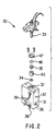
- Figure 2 shows an exploded schematic view of a dual piston metering pump incorporating an inert blanket purge.
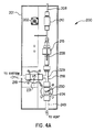
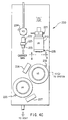
- Figures 4a, 4b and 4c are cutaway views from three angles successively rotated 90° of a vaporizer assembly incorporating the cleaning subassembly of the present invention.
- the view of Figure 4b is rotated 90° about the vertical axis from Figure 4a.
- the view of Figure 4c is rotated 180° about the vertical axis from Figure 4a.
- such aspect of the invention is based on the observation that if the wetted, moving parts of a pump used to pump air- or moisture-sensitive liquids were protected from exposure to air or moisture, the service life of the pump could be dramatically extended. Oxide particle build-up could be avoided or minimized, with a concomitant improvement in pump performance and increase in the interval between service shut-downs which are required to prevent catastrophic seal failure.
- the inert medium is purged through a chamber surrounding the pump's moving, wetted parts.
- the inert medium may be flowed through the chamber continually or intermittently, with the proviso that the atmosphere surrounding the moving, wetted pump parts must be kept substantially free of reactive species such as oxygen or moisture.
- the inert medium is a fluid selected with the criterion that it must not react with the chemical being pumped.
- the inert fluid may be a gas or liquid.
- a dry, inert gas such as argon, nitrogen or helium is a preferred inert medium, although there are cases where ultra-dry air may be adequate.
- Other dry inert gases such as neon, krypton, or hydrogen could also be used.
- the liquid being pumped could be used as the inert fluid medium to purge the pumps wetted parts, in a recirculating system that would be hermetically sealed.
- a low vapor pressure liquid refers to liquids having boiling points above about 150°C.
- the low vapor pressure liquid added to the reagent solution should (1) have a low vapor pressure, (2) be at least moderately soluble in the relatively volatile liquid solvent, and (3) should be a liquid in which the solid reagent is soluble.
- Solid reagents such as those described in U.S. Patent Application Serial No. 07/807,807, "Method for Delivering an Involatile Reagent in Vapor Form to a CVD Reactor," are customarily dissolved in a low-boiling alcohol or ether solvent such as isopropanol or tetrahydrofuran or isopropanol/tetrahydrofuran mixtures.
- the added low volatility liquid can advantageously be a polyether such as tetraglyme (tetraethylene glycol dimethyl ether, boiling point ⁇ 275°C) or triglyme (triethylene glycol dimethyl ether, boiling point ⁇ 216°C).
- Polyamines such as tetraethylenepentamine (boiling point 340°) or triethylenetetramine (boiling point 266-267°C) could also be selected.
- These low volatility liquids are soluble in the alcohol or ether solvent and also dissolve the solid reagents.
- the solvent is isopropanol or an isopropanol/tetrahydrofuran mixture and the solid reagent is a metal beta-diketonate complex
- tetraglyme has been shown to be effective as the low volatility liquid.
- a typical solution is exemplified by 0.1M barium(thd) 2 (bis(2,2,6,6-tetramethyl-3,5-heptanedionato)barium) dissolved in 9:1 isopropanol:tetraglyme.
- the chamber surrounding the pump's wetted parts may be of any suitable size and shape, with the key proviso that a gas or liquid may be flowed through the chamber so as to completely blanket all moving, wetted parts of the pump.
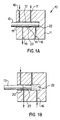
- Figure 1A is a schematic representation of a dual piston metering pump 10 incorporating an inert blanket purge, showing the piston in the fully inserted position, with Figure 1B showing the pump 10 with the piston in the fully withdrawn position.
- Pump block 11 has an interior pumping cavity 12 and a piston 13 positioned in the pumping cavity for reciprocatable movement therein.
- a first liquid seal 14 is mounted in the pumping cavity and circumscribingly arranged about the piston so as (i) to effect sealing between the piston and the pumping cavity during reciprocating movement of the piston in the cavity and (ii) to bound an inner liquid pumping volume 22 of the pumping cavity.
- a second gas seal 15 is mounted in the pumping cavity and circumscribingly arranged about the piston to effect sealing between the piston and the pumping cavity during reciprocating movement of the piston in the cavity, this second gas seal being in spaced-apart relationship to the first liquid seal 14 so as to define an intraseal volume 23 of the pumping cavity therebetween.
- An inlet liquid passage 16 is joined to the inner liquid pumping volume 22 for introduction of feed liquid thereto, and an outlet liquid passage 17 is joined to the inner liquid pumping volume for discharging of pressurized liquid therefrom.
- a gas inlet passage 18 is joined to the intraseal volume 23 of the pumping cavity for introduction of a purge gas thereto, and a gas outlet passage 19 joined to the intraseal volume of the pumping cavity for discharging of the purge gas therefrom.
- a flow of inert gas is maintained at a suitable flow rate, e.g., 0.2 - 5 standard liters per minute (slpm) during the operation of the pump.
- a suitable flow rate e.g., 0.2 - 5 standard liters per minute (slpm) during the operation of the pump.
- FIG. 2 shows an exploded schematic view of a dual piston metering pump 30 incorporating an inert blanket purge.
- Pump block 31 has an interior pumping cavity 32 and a piston 33 which during use is positioned in the pumping cavity for reciprocatable movement therein.
- a first liquid seal 34 is mounted in the pumping cavity with piston seal holder 45 so as to effect sealing between the piston and the pumping cavity during reciprocating movement of the piston in the cavity, and to bound an inner liquid pumping volume of the pumping cavity.
- a gas inlet passage 38 is joined to the intraseal volume of the pumping cavity for introduction of a purge gas thereto, and a gas outlet passage 39 is joined to the intraseal volume of the pumping cavity for discharging of the purge gas therefrom. These are held in place by O-ring 46 and piston seal cover 47 . Thus a portion of the piston during reciprocating movement thereof is translated between the liquid pumping volume of the pumping cavity and the intraseal volume of the pumping cavity.
- such aspect of the invention is based on the observation that under certain conditions, involatile residue can collect in a vaporizer used in a reagent delivery system for a chemical vapor deposition process.
- the average time taken for the build up of these decomposition products to halt the vaporization process will determine the mean time before failure (MTBF) of the liquid delivery system of which the vaporization zone is a subsystem.
- MTBF mean time before failure
- MTR mean time to repair
- the present invention contemplates a method to periodically clean the high surface area vaporization zone of the decomposition products using a suitable cleaning fluid.
- the resulting solution is then flushed into a container which can be removed for disposal or can be connected to provide recycle for reuse.
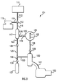
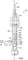
- FIG. 3 A schematic of a chemical vapor deposition system 101 employing the vaporizer flush invention is shown in Figure 3.
- liquid source reagent or solid source reagent dissolved in appropriate solvent flows from reagent source reservoir 111 through fluid conduit 112 to three-way valve 113 , which is in the open position.
- the reagent liquid flows through conduit 116 into vaporizer 117 , which may be of the type described in U.S. Patent No. 5,204,314, "Method For Delivering an Involatile Reagent in Vapor Form to a CVD Reactor".
- the vaporized source reagent flows through conduit 118, on-off valve 119 which is in the open position, and conduit 120 to the chemical vapor deposition reactor chamber 122 , wherein decomposition of the source reagent occurs to deposit films on substrate 121 .
- Decomposition may be thermal, photochemical, plasma-induced, or any other workable type of chemical vapor deposition.
- Waste gases from the CVD reactor, including unreacted source reagent, flow out of the reactor chamber 122 , through conduit 128 and on-off valve 129 which is in the open position to trap or scrubber 130 which retains solids and liquids.
- the trap is connected to the vacuum pump 132 by conduit 131 .
- the scrubber or trap 130 may be a cold trap or any of a wide variety of scrubber types as are well-known in the art. The scrubber or trap protects the vacuum pump.
- Cleaning fluid is held in cleaning fluid reservoir 115 , which may be a liquid vessel/pump combination in the case of liquid cleaning fluids or a gas cylinder in the case of gaseous cleaning fluids.
- cleaning fluid flows from reservoir 115 through conduit 114 to three-way valve 113 , which is in the open position, and thence into the vaporizer 117 , where it is caused to bathe the vaporization structure and thus clean it of any solid or liquid build-up.
- valve 124 may be opened or closed depending on the specific pressure and flow conditions required by the cleaning process and depending on any need for extended contact times for the cleaning fluid to dissolve buildup.
- valve 124 is left open for the entire period that cleaning fluids are introduced to the vaporizer 117 , and the used cleaning fluids continuously flow through conduit 23 and valve 124 and into conduit 125 during the cleaning process.
- on-off valve 119 is in the closed position to prevent cleaning by-products flowing to the CVD reactor vessel 122 .
- On-off valve 29 may be open or closed depending on the nature of any parallel process being run in the CVD chamber 22 . Vapors will continue to flow through conduit 33 into the scrubber or trap 30 , but liquids will flow by gravity through conduit 26 , on-off valve 34 which is in the open position, and into liquid collection reservoir 27 .
- the purpose of the bypass provided by 33 is to prolong the lifetime or extend the time between changeouts or regenerations of the scrubber or trap 30 , by collecting the liquids, which consist mostly of spent cleaning solution, before they can flow into the scrubber or trap.
- On-off valve 34 enables removal and emptying of liquid collection reservoir 27 without complications.
- Figures 4a, 4b and 4c are cutaway views from three angles successively rotated 90° of a vaporizer assembly 200 incorporating the cleaning subassembly of the present invention.
- the view of Figure 4b is rotated 90° about the vertical axis from Figure 4a.
- the view of Figure 4c is rotated 180° about the vertical axis from Figure 4a.
- These drawings were used in the construction of a functional vaporizer assembly with self-cleaning capability.
- the assembly is mounted in casing 201 .
- on-off valve 219 is open, on-off valve 224 is closed, and three-way valve 213 is opened for reagent flow to the vaporizer and closed to cleaning fluid flow to the vaporizer.
- Source reagent liquid or solution flows in through line 211 via the vaporizer element housings 212 and 215 to the vaporization zone 216 .
- Carrier gas flows in through valve fittings 222 and 223 and check valve 225 through conduit 208 and thence through particle filter 210 , which may advantageously be used also as a gas pre-heat zone, because of the particle filter's high surface area.
- the filtered carrier gas flows then flows through conduit 248 and is introduced to vaporization zone 216 , where it mixes with the source reagent. Downstream of vaporization zone 216 , the carrier gas laden with vapor phase source reagent flows into the reactor through valve 219 which is open.
- three-way valve 213 is opened to cleaning fluid flow to the vaporizer, and is closed to reagent flow.
- On-off valve 219 is closed, isolating the CVD reactor from the vaporizer cleaning process.
- on-off valve 224 may either be opened or may be initially closed and then opened for flow of used cleaning fluid to a fluid collection reservoir or gas trap (not shown), depending on the flow and pressure requirements of the cleaning process.
- Cleaning fluid flows in via cleaning fluid port 221 through line 211 via the vaporizer element housings 212 and 215 to the vaporization zone 216 .
- Used cleaning fluid flows out of the vaporization zone via valve 224 , fitting 207 , and conduit 249 to a fluid collection reservoir or gas trap (not shown).
- thermocouples 228 measures temperature of the vaporization zone 216
- 229 measures temperature of the run/vent junction 218
- 230 measures temperature of the vent valve 224
- 231 measures temperature of the valve 219 leading to the reactor chamber. Independent control of these zones provides for the fine tuning required to provide process stability and reproducibility.
- valves are controlled pneumatically, although other modes of control such as manual or electromechanical are also possible.
- Pneumatic control connections 232, 233, 234 , and 235 and pneumatic valve actuators 242, 243, 244 and 245 to valves 219, 224, 225 and 213 respectively are provided.
- Valve status indicators 226 and 227 show the positions of valves 219 and 224 respectively.
- the control of the valves may be manual, by timer, or may be driven by a programmable logic device which is capable of responding to signals from process variable sensors.
- the invention is also applicable to conventional vaporizers in which the chemical vapor deposition reagent reservoir (or "bubbler”) is itself the vaporizer, and hence the generation and accumulation of involatile compounds proceeds by the same mechanisms as described above for vaporizers of compounds that are remotely delivered by a pump as-needed in the process.
- the chemical vapor deposition reagent reservoir or "bubbler”
- the invention may in addition comprise sensing means or a timer mechanism to determine the frequency of the cleaning cycles.
- a sensing mechanism could detect a pressure differential across the vaporizer, the fluid conductance through the vaporizer, light reflectance off the vaporizer structure which would be altered by the build up of solids, radial thermal conductance of the vaporizer, or feedback from the properties of the growing films. All such measurable properties could be used to provide an indication that the vaporizer's performance was deteriorating and it needed to be cleaned.
- the cleaning cycles could be triggered by a timer. Such an approach has the advantage of simplicity and predictability.
- the vaporizer cleaning method of the present invention may optionally include a liquid collection reservoir as shown in Figure 3.
- This liquid collection reservoir provides a number of practical advantages. The lifetime or time between changeouts or regenerations of the scrubber or cold trap may be extended.
- the liquid being collected may be recycled and reused as cleaning fluid or if the source reagent is a highly valuable solid compound that is being deposited prematurely on the vaporizer, it can be repurified and reused.
- the source reagent is toxic, as are barium or thallium compounds for example, the collected liquid contaminated by the toxic substance can provide a more concentrated and easier-to-handle form of the hazardous waste for disposal purposes than would the spent scrubber or more dilute trap residue if the fluid were allowed to flow further into the scrubber or trap 132 .
- a scavenging medium into the liquid collection reservoir, such as a solid, porous chemisorbent, to increase the safety of the personnel responsible for running the reactor. If the cleaning fluid is a strong acid, it may be desirable to neutralize or immobilize it in situ, again for the purpose of enhancing safety. It may also be desirable to control the temperature of the liquid reservoir so that it functions to some degree as a cold trap.
- the porous vaporization element 340 comprises a porous wall member having an outer wall surface which together with the grooves or channels in the vaporization chamber wall provides a flow channel arrangement which distributes the source reagent liquid over the outer wall surface of the vaporization element.
- the flow channel arrangement may be widely varied, and that in some instances, it may be desirable to have a series of grooves or channels parallel to the central axis L-L of the vaporization chamber, which are circumferentially spaced-apart about the periphery of the inner wall surface of the vaporization chamber, and which are interconnected by one or more connecting feed troughs, such as channel 326 in the Figure 5 embodiment.
- porous wall member 340 may itself be variously formed, e.g., with an undulant or grooved surface which cooperates with channels formed in the wall of the vaporization chamber, to accommodate liquid distribution for vaporization thereof.
- the vaporization apparatus could be fabricated with a vaporization chamber wall surface devoid of any channel or passage means therein, and with the porous wall member or other vaporization element constructed so as to form a liquid channel in cooperation with the housing wall in proximity thereto.
- porous wall member in relation to the vaporization chamber wall surface, such as by means of a collar or spacer element which provides an enclosed liquid distribution volume, so that the liquid can enter such plenum space between the outer surface of the porous wall member and the inner wall surface of the vaporization chamber housing, and be readily vaporized.
- the dual piston metering pump equipped with the purge mechanism was used for delivery of 54 ml (50.2 g) of tetrakis(dimethylamido)titanium reagent.
- This titanium reagent is extremely air- and moisture-sensitive, decomposing in air to dimethylamine and solid titanium oxides and/or hydroxides over the space of a few minutes.
- the purged dual piston pump was loaded with tetrakis(dimethylamido)titanium for seven weeks and used to deliver the reagent for greater than 20 hours with no detectable deterioration in the pump seals and no visible build-up of solid decomposition products on the wetted parts.
- a dual piston metering pump was used for delivery of 54 ml (50.2 g) of the TiN reagent.
- the reagent was vaporized at temperatures between 150 to 165°C and the vapor recondensed and collected. 51 ml (47.4g) of reagent was collected, the remaining material having been decomposed in the vaporization zone by either thermal decomposition or by reaction with atmospheric contaminants in the vaporization zone.
- the titanium reagent is extremely air- and moisture-sensitive, decomposing in air to dimethylamine and solid titanium oxides and/or hydroxides over the space of a few minutes.
- aqueous hydrofluoric acid is introduced into the vaporization zone and passed over the surface of the vaporization element.
- the solubility of the titanium decomposition products in the acid allows the surface to be cleaned and the solution of decomposition products to be collected as a liquid.
- the cleaned area is then heated to >100°C under vacuum to remove any residual water.
- the titanium nitride source reagent may then be introduced into the cleaned vaporization zone and delivered as vapor to the CVD reactor chamber.
Landscapes
- Chemical & Material Sciences (AREA)
- Engineering & Computer Science (AREA)
- Chemical Kinetics & Catalysis (AREA)
- Organic Chemistry (AREA)
- General Chemical & Material Sciences (AREA)
- Materials Engineering (AREA)
- Mechanical Engineering (AREA)
- Metallurgy (AREA)
- Inorganic Chemistry (AREA)
- Manufacturing & Machinery (AREA)
- Chemical Vapour Deposition (AREA)
- Feeding, Discharge, Calcimining, Fusing, And Gas-Generation Devices (AREA)
- Details Of Reciprocating Pumps (AREA)
- Feeding And Controlling Fuel (AREA)
- Porous Artificial Stone Or Porous Ceramic Products (AREA)
- Inorganic Compounds Of Heavy Metals (AREA)
Claims (32)
- Appareil pour vaporiser un réactif source de type non vaporeux, pour produire une vapeur servant au transport jusqu'à un lieu d'utilisation, ledit appareil comprenant :caractériséune chambre de vaporisation comprenant une enceinte définissant à l'intérieur de ses limites un volume intérieur fermé de vaporisation ;des moyens pour fournir un réactif source au volume intérieur de l'enceinte ;des moyens de vaporisation disposés dans le volume intérieur de ladite enceinte et en relation de réception avec les moyens d'alimentation, pour recevoir un réactif source et effectuer sa vaporisation ; etdes moyens pour fournir sélectivement au volume intérieur, afin d'établir le contact avec les moyens de vaporisation et les surfaces intérieures de l'enceinte, un fluide de nettoyage qui a une efficacité de nettoyage pour que les dépôts de vaporisation soient au moins partiellement éliminés desdits moyens de vaporisation et desdites surfaces intérieures de l'enceinte ;en ce que la chambre de vaporisation comprend un passage d'écoulement du liquide formé sur une surface de paroi intérieure de fermeture de la chambre de vaporisation ;en ce que les moyens de vaporisation comprennent au moins une paroi poreuse ayant des surfaces de paroi intérieure et extérieure où ladite paroi poreuse est positionnée en ayant sa surface extérieure à proximité de la surface de paroi intérieure de fermeture de la chambre de vaporisation, ledit passage d'écoulement du liquide étant formé sur cette surface de la paroi, de sorte que la surface extérieure de la paroi poreuse recouvre ledit passage d'écoulement du liquide et que la surface intérieure de la paroi poreuse est présentée au volume intérieur de la chambre de vaporisation ;en ce que des moyens sont prévus pour chauffer la paroi poreuse à une température pour la vaporisation du liquide vaporisable ; eten ce que les moyens pour fournir le réactif source au volume intérieur de l'enceinte fournissent le liquide vaporisable au passage d'écoulement du liquide, afin d'établir le contact avec la paroi poreuse chauffée à ladite température de vaporisation du liquide vaporisable, de sorte que la vapeur obtenue, formée par ledit contact, traverse ladite paroi poreuse jusqu'au volume intérieur de la chambre de vaporisation.
- Appareil selon la revendication 1, caractérisé par une chambre de vaporisation de forme cylindrique.
- Appareil selon la revendication 1 ou 2, caractérisé en ce que la chambre de vaporisation est de forme cylindrique, en ce que la paroi poreuse est de forme cylindrique et en ce que la surface extérieure de la paroi poreuse est contiguë à la surface de paroi intérieure de fermeture de la chambre de vaporisation, sur la totalité de la surface extérieure de la paroi poreuse.
- Appareil selon l'une quelconque des revendications 1 à 3,
caractérisé en ce que la paroi poreuse est formée d'un matériau sélectionné à partir de matériaux métalliques frittés et à partir de matières céramiques poreuses. - Appareil selon l'une quelconque des revendications 1 à 4,
caractérisé en ce que le passage d'écoulement du liquide sur la surface de paroi intérieure de fermeture comprend au moins un passage d'écoulement du liquide formant collecteur relié, par communication d'écoulement du liquide, à plusieurs branches de passage d'écoulement du liquide. - Appareil selon la revendication 5, caractérisé en ce que la chambre de vaporisation et la paroi poreuse sont en relation coaxiale l'une par rapport à l'autre et en ce qu'elles sont de type allongé en ayant un axe central longitudinal commun, ledit passage d'écoulement du liquide formant collecteur s'étendant linéairement et parallèlement audit axe central longitudinal, ladite pluralité de branches du passage d'écoulement du fluide étant perpendiculaire audit axe central longitudinal.
- Appareil selon l'une quelconque des revendications 1 à 6 qui comprend en outre des moyens pour introduire un gaz porteur dans ledit volume intérieur de ladite chambre de vaporisation, pour former un mélange de gaz comprenant ledit gaz porteur et ladite vapeur obtenue dans ce volume intérieur de la chambre de vaporisation au cours du fonctionnement dudit appareil.
- Appareil selon l'une quelconque des revendications 1 à 7,
caractérisé en ce que lesdits moyens pour introduire un gaz porteur dans ledit volume intérieur de ladite chambre de vaporisation comprennent un tube perforé et allongé d'alimentation en gaz dans ledit volume intérieur, le tube étant relié, dans la communication de flux de gaz, à une source de gaz porteur, à l'extérieur de la chambre de vaporisation. - Appareil selon l'une quelconque des revendications 1 à 8,
caractérisé en ce que les moyens pour fournir un réactif source, au volume intérieur de l'enceinte, comprennent une pompe, où ladite pompe comprend :un corps de pompe comprenant une cavité intérieure de pompage ;un piston positionné dans la cavité de pompage pour un mouvement alternatif à l'intérieur de la cavité ;un premier joint à liquide monté dans la cavité de pompage et disposé circonférentiellement autour du piston, (i) pour assurer l'étanchéité entre le piston et la cavité de pompage au cours du mouvement alternatif du piston dans la cavité, et (ii) pour limiter un volume intérieur de pompage du liquide de la cavité de pompage ;un second joint à fluide monté dans la cavité de pompage et disposé circonférentiellement autour du piston, pour assurer l'étanchéité entre le piston et la cavité de pompage au cours du mouvement alternatif du piston dans la cavité, le second joint à fluide étant espacé par rapport au premier joint à liquide, pour définir un volume, entre joints, de la cavité de pompage;un passage d'entrée du liquide relié au volume intérieur de pompage du liquide, pour l'introduction du liquide d'alimentation jusqu'à ce volume intérieur ;un passage de sortie du liquide relié au volume intérieur de pompage du liquide, pour que le liquide pressurisé soit évacué de ce volume intérieur ;un passage d'entrée du fluide relié au volume entre joints de la cavité de pompage, pour l'introduction d'un gaz ou d'un liquide de purge jusqu'à ce volume entre joints ; etun passage de sortie du fluide relié au volume entre joints de la cavité de pompage pour qu'un gaz de purge ou un liquide soit évacué de ce volume entre joints,où une partie du piston, au cours de son mouvement alternatif, suit un mouvement de translation entre le volume de pompage du liquide de la cavité de pompage et le volume entre joints de la cavité de pompage. - Appareil selon la revendication 9, caractérisé en ce que les moyens fournissant le liquide d'alimentation sont reliés, en fournissant le liquide, au passage d'entrée du liquide.
- Appareil selon la revendication 9 ou 10, caractérisé en ce que les moyens d'alimentation en fluide de purge sont reliés, en fournissant le fluide, au passage d'entrée du fluide.
- Appareil selon l'une quelconque des revendications 9 à 11, caractérisé en ce que le corps de pompe comprend un corps métallique unitaire usiné.
- Utilisation d'un appareil selon la revendication 9, pour effectuer un processus afin d'empêcher la corrosion et/ou la formation de matières particulaires dans ladite pompe,
caractérisée en ce que ladite pompe est adaptée pour pomper un liquide empêchant ladite corrosion et/ou ladite formation de matières particulaires en présence d'oxygène et/ou d'autres gaz atmosphériques,
où le piston alternatif peut suivre un mouvement alternatif entre une première position sortie dans la cavité de pompage de la pompe, et une seconde position rentrée, à l'extérieur de la cavité de pompage, de sorte qu'une partie active du pompage du piston alternatif vient en contact séquentiellement et de façon répétée avec le liquide dans la chambre de pompage du liquide, puis est retirée à l'extérieur de la chambre de pompage du liquide, où la partie active de pompage du piston alternatif, à l'extérieur de la chambre de pompage du liquide, est recouverte d'un fluide inerte, de sorte que la partie active de pompage du piston alternatif est empêchée de venir en contact avec l'oxygène ou avec d'autres gaz atmosphériques. - Utilisation selon la revendication 13, dans laquelle le fluide inerte est sélectionné parmi l'argon, l'azote, l'hélium et l'hydrogène.
- Utilisation selon la revendication 13 ou 14 qui comprend en outre le mouvement alternatif du piston dans la cavité de pompage ; l'écoulement du liquide d'alimentation à travers le passage du liquide d'entrée jusqu'à la cavité de pompage ; l'évacuation du liquide pressurisé sortant de la cavité de pompage, à travers le passage de sortie du liquide ; l'écoulement du fluide de purge à travers le passage d'entrée du fluide jusque dans le volume entre joints de la cavité de pompage et l'évacuation du fluide de purge sortant du volume entre joints de la cavité de pompage, à travers le passage de sortie du fluide.
- Utilisation selon la revendication 13 ou 14, dans laquelle ledit processus comprend l'étape consistant à mélanger le liquide du processus avec un composant liquide à faible pression de vapeur qui est efficace, par solvatation, pour empêcher la corrosion ou la formation de matières particulaires, suivant une quantité efficace pour ladite action inhibitrice.
- Utilisation selon la revendication 16, dans laquelle le liquide à faible pression de vapeur est sélectionné parmi des polyéthers, des polyamines et des amines aromatiques.
- Utilisation selon la revendication 16, dans laquelle le liquide à faible pression de vapeur est sélectionné à partir du tétraglyme, du triglyme, du diglyme, de la tétraéthylènepentamine et de la triéthylènetétramine.
- Utilisation selon l'une quelconque des revendications 16 à 18, dans laquelle le liquide du processus est une solution d'un complexe de bêta-dicétonate métallique dans un solvant à point d'ébullition bas, le liquide à faible pression de vapeur étant sélectionné parmi du tétraglyme, du triglyme ou du diglyme.
- Utilisation d'un appareil selon la revendication 9, pour effectuer un processus afin d'empêcher la corrosion et/ou la formation de matières particulaires dans la pompe,
caractérisée par au moins une des étapes consistant :à mélanger le liquide du processus avec un composant liquide à faible pression de vapeur qui est efficace, par solvatation, pour empêcher la corrosion ou la formation de matières particulaires suivant une quantité efficace pour ladite action inhibitrice ; età recouvrir l'extérieur du piston de la cavité de pompage avec un fluide inerte, de sorte que la partie active de pompage du piston alternatif est empêchée de venir en contact avec l'oxygène ou avec d'autres gaz atmosphériques. - Appareil pour vaporiser un réactif source de type non vaporeux, afin de produire une vapeur servant au transport jusqu'à un lieu d'utilisation, ledit appareil comprenant :caractérisé par des moyens pour fournir sélectivement au volume intérieur, afin d'établir le contact avec les moyens de vaporisation et avec des surfaces intérieures de l'enceinte, un fluide de nettoyage qui a une efficacité de nettoyage pour que les dépôts de vaporisation soient au moins partiellement éliminés desdits moyens de vaporisation et desdites surfaces intérieures de l'enceinte reliée, dans la relation d'écoulement du réactif vaporisé, à une chambre de dépôt en aval, les flux du fluide de nettoyage, du réactif source et du réactif vaporisé étant sélectivement régulés avec des moyens de régulation de l'écoulement, ces moyens de régulation étant du type actionnable sélectivement et interconnectés avec des moyens de synchronisation du cycle, pour produire une séquence de vaporisation du réactif source et pour fournir ce même réactif source vaporisé à la chambre de dépôt en aval, pour une première partie prédéterminée du cycle, suivie de l'arrêt de l'écoulement du réactif source et du réactif vaporisé, et suivie de l'écoulement du fluide de nettoyage dans la chambre pour le nettoyage de celle-ci, les moyens de synchronisation du cycle comprenant des moyens pour détecter une variable du système sélectionnée parmi le groupe se composant : d'un différentiel de pression dans le vaporisateur ; de la conductance du fluide à travers le vaporisateur ; de la réflexion de la lumière hors de la structure du vaporisateur à une longueur d'onde où une telle réflexion est modifiée par la formation de solides ; de la conductance thermique radiale du vaporisateur et de la rétroaction des propriétés des films croissants.une chambre de vaporisation comprenant une enceinte définissant à l'intérieur de ses limites un volume intérieur fermé de vaporisation ;des moyens pour fournir un réactif source au volume intérieur de l'enceinte ;des moyens de vaporisation disposés dans le volume intérieur de ladite enceinte et en relation de réception avec les moyens d'alimentation, pour recevoir un réactif source et pour effectuer sa vaporisation ;
- Procédé de vaporisation d'un réactif source non vaporeux et d'élimination au moins partiellement de sous-produits de déposition d'une telle vaporisation, ledit procédé comprenant les étapes consistant :caractérisé :à réaliser un appareil pour vaporiser un réactif source de type non vaporeux, afin de produire une vapeur servant au transport jusqu'à un lieu d'utilisation, ledit appareil comprenant :une chambre de vaporisation comprenant une enceinte définissant à l'intérieur de ses limites un volume intérieur fermé de vaporisation ;des moyens pour fournir un réactif source, au volume intérieur de l'enceinte ;des moyens de vaporisation disposés dans le volume intérieur de ladite enceinte et en relation de réception avec les moyens d'alimentation, pour recevoir un réactif source et pour effectuer sa vaporisation ; età vaporiser le réactif source dans l'enceinte pendant un laps de temps prédéterminé et à faire en sorte que le réactif vaporisé obtenu s'écoule hors de l'enceinte ;en ce que ledit appareil comprend des moyens pour fournir sélectivement au volume intérieur, afin d'établir le contact avec les moyens de vaporisation et les surfaces intérieures de l'enceinte, un fluide de nettoyage qui a une efficacité de nettoyage pour que les dépôts de vaporisation soient au moins partiellement éliminés desdits moyens de vaporisation et desdites surfaces intérieures de l'enceinte ; etaprès un laps de temps prédéterminé, le procédé comprend l'étape consistant à achever l'écoulement du réactif source et du réactif vaporisé, et à faire en sorte qu'un fluide de nettoyage s'écoule dans ladite enceinte, le fluide de nettoyage ayant une efficacité de nettoyage pour que les produits de dépôts dus à ladite vaporisation soient au moins partiellement éliminés.
- Procédé selon la revendication 22, comprenant en outre les étapes consistant à faire en sorte que le réactif vaporisé quitte l'enceinte pour s'acheminer jusqu'à une zone de dépôt chimique en phase vapeur et à effectuer le dépôt chimique en phase vapeur à partir du réactif vaporisé dans ladite zone.
- Procédé selon la revendication 22 ou 23, dans lequel le fluide de nettoyage comprend un solvant organique.
- Procédé selon la revendication 24, dans lequel le fluide de nettoyage est sélectionné parmi au moins un des éléments suivants tels que des alcools, des éthers, des polyéthers, des polyamines ou des mélanges de ces éléments.
- Procédé selon la revendication 24, dans lequel le fluide de nettoyage comprend une polyamine.
- Procédé selon la revendication 22, dans lequel le fluide de nettoyage comprend du fluorure d'hydrogène.
- Procédé selon la revendication 22, dans lequel le fluide de nettoyage comprend du tétrahydrofurane.
- Procédé selon la revendication 22, dans lequel le fluide de nettoyage comprend un solvant d'un type présent dans le réactif source.
- Procédé selon la revendication 22, dans lequel l'enceinte est reliée, dans la relation d'écoulement du réactif vaporisé, à une chambre de dépôt en aval, et où les flux du fluide de nettoyage, du réactif source et du réactif vaporisé sont régulés sélectivement avec les moyens de régulation d'écoulement, ces moyens de régulation étant du type actionnable sélectivement.
- Procédé selon la revendication 22, dans lequel les moyens de régulation d'écoulement sont interconnectés avec des moyens de synchronisation du cycle, pour produire une séquence de vaporisation du réactif source et pour fournir ce même réactif source vaporisé à la chambre de dépôt en aval, pendant une première partie prédéterminée du cycle, suivie de l'arrêt de l'écoulement du réactif source et du réactif vaporisé, et suivie de l'écoulement du fluide de nettoyage dans la chambre de dépôt pour le nettoyage de celle-ci.
- Système de dépôt chimique en phase vapeur, comprenant :
un appareil pour vaporiser un liquide vaporisable, comprenant :caractérisé :une chambre de vaporisation renfermant un volume intérieur et limité au moins partiellement par une surface de paroi intérieure de fermeture ;un élément de vaporisation disposé dans ladite chambre de vaporisation ;des moyens pour chauffer l'élément de vaporisation à une température de vaporisation du liquide vaporisable ;des moyens pour fournir un liquide vaporisable, à l'élément de vaporisation comprenant une pompe ; etdes moyens pour évacuer la vapeur sortant du volume intérieur de la chambre de vaporisation ;(A) par un passage d'écoulement du liquide formé sur ladite surface de paroi intérieure de fermeture ;(B) par des moyens de vaporisation comprenant au moins une paroi poreuse ayant des surfaces de paroi intérieure et extérieure où ladite paroi poreuse est positionnée en ayant sa surface extérieure à proximité de la surface de paroi intérieure de fermeture, pour former, en coopération avec cette surface de paroi intérieure de fermeture, ledit passage d'écoulement du liquide, de sorte que la surface extérieure de la paroi poreuse recouvre ledit passage d'écoulement du liquide et que la surface intérieure de la paroi poreuse est présentée au volume intérieur de la chambre de vaporisation ;(C) par ledit ensemble de pompage comprenant :un corps de pompe comprenant une cavité intérieure de pompage ;un piston positionné dans la cavité de pompage pour un mouvement alternatif à l'intérieur de la cavité ;un premier joint à liquide monté dans la cavité de pompage et disposé circonférentiellement autour du piston, (i) pour assurer l'étanchéité entre le piston et la cavité de pompage au cours du mouvement alternatif du piston dans la cavité, et (ii) pour limiter un volume intérieur de pompage du liquide de la cavité de pompage ;un second joint à fluide monté dans la cavité de pompage et disposé circonférentiellement autour du piston, pour assurer l'étanchéité entre le piston et la cavité de pompage au cours du mouvement alternatif du piston dans la cavité, le second joint à fluide étant espacé par rapport au premier joint à liquide, pour définir un volume, entre joints, de la cavité de pompage;un passage d'entrée du liquide relié au volume intérieur de pompage du liquide, pour l'introduction du liquide d'alimentation jusqu'à ce volume intérieur ;un passage de sortie du liquide relié au volume intérieur de pompage du liquide, pour que le liquide pressurisé soit évacué de ce volume intérieur ;un passage d'entrée du fluide relié au volume entre joints de la cavité de pompage, pour l'introduction d'un gaz ou d'un liquide de purge jusqu'à ce volume entre joints ; etun passage de sortie du fluide relié au volume entre joints de la cavité de pompage pour qu'un gaz de purge ou un liquide soit évacué de ce volume entre joints,où une partie du piston, au cours de son mouvement alternatif, suit un mouvement de translation entre le volume de pompage du liquide de la cavité de pompage et le volume entre joints de la cavité de pompage ; et(D) par des moyens pour fournir sélectivement au volume intérieur, afin d'établir le contact avec l'élément de vaporisation et avec les surfaces intérieures de l'enceinte, un fluide de nettoyage qui a une efficacité de nettoyage pour que les dépôts de vaporisation soient au moins partiellement éliminés dudit élément de vaporisation et desdites surfaces intérieures de l'enceinte.
Applications Claiming Priority (5)
| Application Number | Priority Date | Filing Date | Title |
|---|---|---|---|
| US32984 | 1993-03-18 | ||
| US08/032,984 US5337651A (en) | 1990-07-06 | 1993-03-18 | Apparatus and method for protection of pumps used for delivery of air- or moisture-sensitive liquids |
| US178933 | 1994-01-07 | ||
| US08/178,933 US5362328A (en) | 1990-07-06 | 1994-01-07 | Apparatus and method for delivering reagents in vapor form to a CVD reactor, incorporating a cleaning subsystem |
| PCT/US1994/002512 WO1994021840A1 (fr) | 1993-03-18 | 1994-03-07 | Appareil et methode d'introduction de reactifs en phase gazeuse dans un reacteur de deposition en phase gazeuse par procede chimique (cvd) |
Publications (3)
| Publication Number | Publication Date |
|---|---|
| EP0689619A1 EP0689619A1 (fr) | 1996-01-03 |
| EP0689619A4 EP0689619A4 (fr) | 1998-07-15 |
| EP0689619B1 true EP0689619B1 (fr) | 2001-05-30 |
Family
ID=26709139
Family Applications (1)
| Application Number | Title | Priority Date | Filing Date |
|---|---|---|---|
| EP94913894A Expired - Lifetime EP0689619B1 (fr) | 1993-03-18 | 1994-03-07 | Appareil et methode d'introduction de reactifs en phase gazeuse dans un reacteur de deposition en phase gazeuse par procede chimique (cvd) |
Country Status (7)
| Country | Link |
|---|---|
| EP (1) | EP0689619B1 (fr) |
| JP (1) | JP3103596B2 (fr) |
| KR (1) | KR100320762B1 (fr) |
| AT (1) | ATE201721T1 (fr) |
| CA (1) | CA2158434A1 (fr) |
| DE (1) | DE69427346T2 (fr) |
| WO (1) | WO1994021840A1 (fr) |
Cited By (1)
| Publication number | Priority date | Publication date | Assignee | Title |
|---|---|---|---|---|
| EP4078660A4 (fr) * | 2019-12-18 | 2024-02-07 | L'air Liquide, Societe Anonyme Pour L'etude Et L'exploitation Des Procedes Georges Claude | Systèmes de distribution de vapeur pour matériaux solides et liquide |
Families Citing this family (20)
| Publication number | Priority date | Publication date | Assignee | Title |
|---|---|---|---|---|
| JP3335492B2 (ja) | 1994-12-28 | 2002-10-15 | 三菱電機株式会社 | 薄膜の堆積装置 |
| EP0814177A3 (fr) * | 1996-05-23 | 2000-08-30 | Ebara Corporation | Dispositif évaporateur et dispositif utilisant celui-ci pour la déposition de films |
| WO1999004060A1 (fr) * | 1997-07-14 | 1999-01-28 | Advanced Technology Materials, Inc. | Procede et appareil d'administration de fluide |
| US6216708B1 (en) * | 1998-07-23 | 2001-04-17 | Micron Technology, Inc. | On-line cleaning method for CVD vaporizers |
| US7163197B2 (en) | 2000-09-26 | 2007-01-16 | Shimadzu Corporation | Liquid substance supply device for vaporizing system, vaporizer, and vaporization performance appraisal method |
| JP2003137512A (ja) * | 2001-11-02 | 2003-05-14 | Rigaku Corp | 金属酸化物の製造方法,半導体装置及び金属酸化物製造装置 |
| US6921062B2 (en) | 2002-07-23 | 2005-07-26 | Advanced Technology Materials, Inc. | Vaporizer delivery ampoule |
| US8865271B2 (en) * | 2003-06-06 | 2014-10-21 | Neophotonics Corporation | High rate deposition for the formation of high quality optical coatings |
| US20080241805A1 (en) | 2006-08-31 | 2008-10-02 | Q-Track Corporation | System and method for simulated dosimetry using a real time locating system |
| KR20200124780A (ko) | 2012-05-31 | 2020-11-03 | 엔테그리스, 아이엔씨. | 배취식 침착을 위한 고 물질 플럭스를 갖는 유체의 소스 시약-기반 수송 |
| US10443128B2 (en) * | 2015-04-18 | 2019-10-15 | Versum Materials Us, Llc | Vessel and method for delivery of precursor materials |
| KR102643986B1 (ko) | 2017-09-29 | 2024-03-07 | 사빅 에스케이 넥슬렌 컴퍼니 피티이 엘티디 | 신규한 인덴계 전이금속 화합물, 이를 포함하는 전이금속 촉매 조성물, 및 이를 이용한 에틸렌 단독중합체 또는 에틸렌과 α-올레핀의 공중합체의 제조방법 |
| KR102714698B1 (ko) | 2019-02-28 | 2024-10-10 | 사빅 에스케이 넥슬렌 컴퍼니 피티이 엘티디 | 신규한 테트라아릴보레이트 화합물, 이를 포함하는 촉매 조성물, 및 이를 이용한 에틸렌 단독중합체 또는 에틸렌과 α-올레핀의 공중합체의 제조방법 |
| JP6943911B2 (ja) * | 2019-03-07 | 2021-10-06 | 古河電気工業株式会社 | 気化器の洗浄方法および気化装置 |
| KR102888777B1 (ko) | 2019-12-30 | 2025-11-21 | 사빅 에스케이 넥슬렌 컴퍼니 피티이 엘티디 | 전자 당김 그룹을 갖는 금속-리간드 착체, 이를 포함하는 에틸렌계 중합체 제조용 촉매 조성물 및 이를 이용한 에틸렌계 중합체의 제조방법 |
| KR20220094138A (ko) | 2020-12-28 | 2022-07-05 | 사빅 에스케이 넥슬렌 컴퍼니 피티이 엘티디 | 금속-리간드 착체, 이를 포함하는 에틸렌계 중합체 제조용 촉매 조성물 및 이를 이용한 에틸렌계 중합체의 제조방법 |
| KR20230101716A (ko) | 2021-12-29 | 2023-07-06 | 사빅 에스케이 넥슬렌 컴퍼니 피티이 엘티디 | 전이금속 화합물, 이를 포함하는 촉매 조성물 및 이를 이용하는 올레핀 중합체의 제조방법 |
| KR20230101717A (ko) | 2021-12-29 | 2023-07-06 | 사빅 에스케이 넥슬렌 컴퍼니 피티이 엘티디 | 금속-리간드 착체, 이를 포함하는 에틸렌계 중합체 제조용 촉매 조성물 및 이를 이용한 에틸렌계 중합체의 제조방법 |
| KR20240049151A (ko) | 2022-10-07 | 2024-04-16 | 사빅 에스케이 넥슬렌 컴퍼니 피티이 엘티디 | 전이금속 화합물, 이를 포함하는 촉매 조성물 및 이를 이용하는 올레핀 중합체의 제조방법 |
| KR20250085604A (ko) | 2023-12-05 | 2025-06-12 | 사빅 에스케이 넥슬렌 컴퍼니 피티이 엘티디 | 전이금속 화합물, 이를 포함하는 촉매 조성물 및 이를 이용한 올레핀 중합체의 제조방법 |
Family Cites Families (13)
| Publication number | Priority date | Publication date | Assignee | Title |
|---|---|---|---|---|
| FR1097534A (fr) * | 1953-04-02 | 1955-07-06 | Burckhardt Ag Maschf | Procédé pour maintenir exempte d'huile la tige de piston dans les machines à piston, et machine à piston agencée pour la mise en oeuvre de ce procédé |
| US4036915A (en) | 1973-01-02 | 1977-07-19 | Meloy Laboratories, Inc. | Temperature-controlled apparatus for fluid permeation or the like |
| GB1584814A (en) * | 1976-08-23 | 1981-02-18 | Champion Chemicals Inc | Stream testing and treating system and method |
| US4174929A (en) * | 1977-03-11 | 1979-11-20 | Dudin Jury A | High pressure pump |
| US4288369A (en) | 1977-07-19 | 1981-09-08 | Western Kentucky University | Production of cyclic ethers |
| US4212663A (en) * | 1978-01-26 | 1980-07-15 | Corning Glass Works | Reactants delivery system for optical waveguide manufacturing |
| US4288396A (en) * | 1978-11-17 | 1981-09-08 | Ottestad Nils T | Method and device for conditioning of breathing air for divers |
| NO152764C (no) | 1983-07-25 | 1985-11-13 | Kleven Loland As | Tetningsanordning for en hoeytrykks aksialstempelpumpe. |
| JP2662993B2 (ja) * | 1988-08-10 | 1997-10-15 | 株式会社高純度化学研究所 | 液体原料気化装置 |
| EP0420596B1 (fr) * | 1989-09-26 | 1996-06-19 | Canon Kabushiki Kaisha | Dispositif d'alimentation en gaz et appareillage de disposition de films l'employant |
| US5204314A (en) * | 1990-07-06 | 1993-04-20 | Advanced Technology Materials, Inc. | Method for delivering an involatile reagent in vapor form to a CVD reactor |
| GB9116381D0 (en) * | 1991-07-30 | 1991-09-11 | Shell Int Research | Method for deposition of a metal |
| US5259995A (en) * | 1991-10-30 | 1993-11-09 | Liquid Carbonic Industries Corporation | Vapor pressure device |
-
1994
- 1994-03-07 EP EP94913894A patent/EP0689619B1/fr not_active Expired - Lifetime
- 1994-03-07 AT AT94913894T patent/ATE201721T1/de not_active IP Right Cessation
- 1994-03-07 KR KR1019950703951A patent/KR100320762B1/ko not_active Expired - Fee Related
- 1994-03-07 DE DE69427346T patent/DE69427346T2/de not_active Expired - Fee Related
- 1994-03-07 CA CA002158434A patent/CA2158434A1/fr not_active Abandoned
- 1994-03-07 JP JP06521092A patent/JP3103596B2/ja not_active Expired - Fee Related
- 1994-03-07 WO PCT/US1994/002512 patent/WO1994021840A1/fr not_active Ceased
Cited By (1)
| Publication number | Priority date | Publication date | Assignee | Title |
|---|---|---|---|---|
| EP4078660A4 (fr) * | 2019-12-18 | 2024-02-07 | L'air Liquide, Societe Anonyme Pour L'etude Et L'exploitation Des Procedes Georges Claude | Systèmes de distribution de vapeur pour matériaux solides et liquide |
Also Published As
| Publication number | Publication date |
|---|---|
| WO1994021840A1 (fr) | 1994-09-29 |
| JPH08508315A (ja) | 1996-09-03 |
| DE69427346T2 (de) | 2001-09-13 |
| CA2158434A1 (fr) | 1994-09-29 |
| ATE201721T1 (de) | 2001-06-15 |
| DE69427346D1 (de) | 2001-07-05 |
| EP0689619A1 (fr) | 1996-01-03 |
| EP0689619A4 (fr) | 1998-07-15 |
| KR100320762B1 (ko) | 2002-08-08 |
| JP3103596B2 (ja) | 2000-10-30 |
| KR960701235A (ko) | 1996-02-24 |
Similar Documents
| Publication | Publication Date | Title |
|---|---|---|
| EP0689619B1 (fr) | Appareil et methode d'introduction de reactifs en phase gazeuse dans un reacteur de deposition en phase gazeuse par procede chimique (cvd) | |
| US5362328A (en) | Apparatus and method for delivering reagents in vapor form to a CVD reactor, incorporating a cleaning subsystem | |
| US5337651A (en) | Apparatus and method for protection of pumps used for delivery of air- or moisture-sensitive liquids | |
| US5882416A (en) | Liquid delivery system, heater apparatus for liquid delivery system, and vaporizer | |
| US5919522A (en) | Growth of BaSrTiO3 using polyamine-based precursors | |
| CN102272351B (zh) | 试剂分配装置及输送方法 | |
| KR100366249B1 (ko) | 액체반응원공급장치및이장치를구비하는화학증착장치 | |
| US6620256B1 (en) | Non-plasma in-situ cleaning of processing chambers using static flow methods | |
| KR100561883B1 (ko) | 용매 퍼지에 의해 화학물질을 공급하기 위한 장치 및 방법 | |
| CN101514446A (zh) | 多安瓿输送系统 | |
| US20060133955A1 (en) | Apparatus and method for delivering vapor phase reagent to a deposition chamber | |
| US7687110B2 (en) | Method of in-line purification of CVD reactive precursor materials | |
| Kirlin et al. | MOCVD of BaSrTiO3 for ULSI DRAMs | |
| KR20090125242A (ko) | 반응물 분배 장치 및 전달 방법 | |
| KR20160134544A (ko) | 증착 공정에서 화학적 전구체를 위한 용기 | |
| KR101585242B1 (ko) | 반응물 분배 장치 및 송출 방법 | |
| KR101530100B1 (ko) | 건식 펌프 표면으로부터의 반도체 처리 잔류물의 인-시튜 제거 | |
| CN101569841B (zh) | 试剂分配装置及输送方法 | |
| US20080206445A1 (en) | Selective separation processes | |
| KR102897756B1 (ko) | 세정 장치를 구비한 기화 시스템 및 이를 세정하는 세정 방법 | |
| EP1021588A1 (fr) | Procede et appareil d'administration de fluide |
Legal Events
| Date | Code | Title | Description |
|---|---|---|---|
| PUAI | Public reference made under article 153(3) epc to a published international application that has entered the european phase |
Free format text: ORIGINAL CODE: 0009012 |
|
| 17P | Request for examination filed |
Effective date: 19951009 |
|
| AK | Designated contracting states |
Kind code of ref document: A1 Designated state(s): AT BE CH DE DK ES FR GB GR IE IT LI LU MC NL PT SE |
|
| A4 | Supplementary search report drawn up and despatched |
Effective date: 19980602 |
|
| AK | Designated contracting states |
Kind code of ref document: A4 Designated state(s): AT BE CH DE DK ES FR GB GR IE IT LI LU MC NL PT SE |
|
| 17Q | First examination report despatched |
Effective date: 19981023 |
|
| GRAG | Despatch of communication of intention to grant |
Free format text: ORIGINAL CODE: EPIDOS AGRA |
|
| GRAG | Despatch of communication of intention to grant |
Free format text: ORIGINAL CODE: EPIDOS AGRA |
|
| GRAH | Despatch of communication of intention to grant a patent |
Free format text: ORIGINAL CODE: EPIDOS IGRA |
|
| GRAH | Despatch of communication of intention to grant a patent |
Free format text: ORIGINAL CODE: EPIDOS IGRA |
|
| GRAA | (expected) grant |
Free format text: ORIGINAL CODE: 0009210 |
|
| AK | Designated contracting states |
Kind code of ref document: B1 Designated state(s): AT BE CH DE DK ES FR GB GR IE IT LI LU MC NL PT SE |
|
| PG25 | Lapsed in a contracting state [announced via postgrant information from national office to epo] |
Ref country code: LI Free format text: LAPSE BECAUSE OF FAILURE TO SUBMIT A TRANSLATION OF THE DESCRIPTION OR TO PAY THE FEE WITHIN THE PRESCRIBED TIME-LIMIT Effective date: 20010530 Ref country code: IT Free format text: LAPSE BECAUSE OF FAILURE TO SUBMIT A TRANSLATION OF THE DESCRIPTION OR TO PAY THE FEE WITHIN THE PRESCRIBED TIME-LIMIT;WARNING: LAPSES OF ITALIAN PATENTS WITH EFFECTIVE DATE BEFORE 2007 MAY HAVE OCCURRED AT ANY TIME BEFORE 2007. THE CORRECT EFFECTIVE DATE MAY BE DIFFERENT FROM THE ONE RECORDED. Effective date: 20010530 Ref country code: CH Free format text: LAPSE BECAUSE OF FAILURE TO SUBMIT A TRANSLATION OF THE DESCRIPTION OR TO PAY THE FEE WITHIN THE PRESCRIBED TIME-LIMIT Effective date: 20010530 Ref country code: BE Free format text: LAPSE BECAUSE OF FAILURE TO SUBMIT A TRANSLATION OF THE DESCRIPTION OR TO PAY THE FEE WITHIN THE PRESCRIBED TIME-LIMIT Effective date: 20010530 Ref country code: AT Free format text: LAPSE BECAUSE OF FAILURE TO SUBMIT A TRANSLATION OF THE DESCRIPTION OR TO PAY THE FEE WITHIN THE PRESCRIBED TIME-LIMIT Effective date: 20010530 |
|
| REF | Corresponds to: |
Ref document number: 201721 Country of ref document: AT Date of ref document: 20010615 Kind code of ref document: T |
|
| REG | Reference to a national code |
Ref country code: CH Ref legal event code: EP |
|
| REF | Corresponds to: |
Ref document number: 69427346 Country of ref document: DE Date of ref document: 20010705 |
|
| REG | Reference to a national code |
Ref country code: IE Ref legal event code: FG4D |
|
| PG25 | Lapsed in a contracting state [announced via postgrant information from national office to epo] |
Ref country code: SE Free format text: LAPSE BECAUSE OF FAILURE TO SUBMIT A TRANSLATION OF THE DESCRIPTION OR TO PAY THE FEE WITHIN THE PRESCRIBED TIME-LIMIT Effective date: 20010830 Ref country code: PT Free format text: LAPSE BECAUSE OF FAILURE TO SUBMIT A TRANSLATION OF THE DESCRIPTION OR TO PAY THE FEE WITHIN THE PRESCRIBED TIME-LIMIT Effective date: 20010830 Ref country code: DK Free format text: LAPSE BECAUSE OF FAILURE TO SUBMIT A TRANSLATION OF THE DESCRIPTION OR TO PAY THE FEE WITHIN THE PRESCRIBED TIME-LIMIT Effective date: 20010830 |
|
| PG25 | Lapsed in a contracting state [announced via postgrant information from national office to epo] |
Ref country code: GR Free format text: LAPSE BECAUSE OF FAILURE TO SUBMIT A TRANSLATION OF THE DESCRIPTION OR TO PAY THE FEE WITHIN THE PRESCRIBED TIME-LIMIT Effective date: 20010831 |
|
| ET | Fr: translation filed | ||
| PG25 | Lapsed in a contracting state [announced via postgrant information from national office to epo] |
Ref country code: ES Free format text: LAPSE BECAUSE OF FAILURE TO SUBMIT A TRANSLATION OF THE DESCRIPTION OR TO PAY THE FEE WITHIN THE PRESCRIBED TIME-LIMIT Effective date: 20011130 |
|
| REG | Reference to a national code |
Ref country code: CH Ref legal event code: PL |
|
| REG | Reference to a national code |
Ref country code: GB Ref legal event code: IF02 |
|
| PG25 | Lapsed in a contracting state [announced via postgrant information from national office to epo] |
Ref country code: MC Free format text: LAPSE BECAUSE OF NON-PAYMENT OF DUE FEES Effective date: 20020307 Ref country code: LU Free format text: LAPSE BECAUSE OF NON-PAYMENT OF DUE FEES Effective date: 20020307 |
|
| PLBE | No opposition filed within time limit |
Free format text: ORIGINAL CODE: 0009261 |
|
| STAA | Information on the status of an ep patent application or granted ep patent |
Free format text: STATUS: NO OPPOSITION FILED WITHIN TIME LIMIT |
|
| 26N | No opposition filed | ||
| PG25 | Lapsed in a contracting state [announced via postgrant information from national office to epo] |
Ref country code: FR Free format text: LAPSE BECAUSE OF NON-PAYMENT OF DUE FEES Effective date: 20021129 |
|
| REG | Reference to a national code |
Ref country code: IE Ref legal event code: MM4A |
|
| REG | Reference to a national code |
Ref country code: FR Ref legal event code: ST |
|
| PG25 | Lapsed in a contracting state [announced via postgrant information from national office to epo] |
Ref country code: IE Free format text: LAPSE BECAUSE OF NON-PAYMENT OF DUE FEES Effective date: 20030307 |
|
| PGFP | Annual fee paid to national office [announced via postgrant information from national office to epo] |
Ref country code: GB Payment date: 20030312 Year of fee payment: 10 |
|
| PGFP | Annual fee paid to national office [announced via postgrant information from national office to epo] |
Ref country code: DE Payment date: 20030320 Year of fee payment: 10 |
|
| PGFP | Annual fee paid to national office [announced via postgrant information from national office to epo] |
Ref country code: NL Payment date: 20030327 Year of fee payment: 10 |
|
| PGFP | Annual fee paid to national office [announced via postgrant information from national office to epo] |
Ref country code: IE Payment date: 20030801 Year of fee payment: 9 |
|
| REG | Reference to a national code |
Ref country code: IE Ref legal event code: MM4A Free format text: ERRATA: IN JOURNAL NUMBER 1959 OF 20030108, IN THE LIST OF PATENTS LAPSED THROUGH NON-PAYMENT OF RENEWAL FEES, PATENT NUMBER 0689619 WAS LISTED IN ERROR. THIS PATENT IS STILL IN FORCE. |
|
| REG | Reference to a national code |
Ref country code: IE Ref legal event code: MM4A |
|
| PG25 | Lapsed in a contracting state [announced via postgrant information from national office to epo] |
Ref country code: GB Free format text: LAPSE BECAUSE OF NON-PAYMENT OF DUE FEES Effective date: 20040307 |
|
| PG25 | Lapsed in a contracting state [announced via postgrant information from national office to epo] |
Ref country code: NL Free format text: LAPSE BECAUSE OF NON-PAYMENT OF DUE FEES Effective date: 20041001 Ref country code: DE Free format text: LAPSE BECAUSE OF NON-PAYMENT OF DUE FEES Effective date: 20041001 |
|
| GBPC | Gb: european patent ceased through non-payment of renewal fee | ||
| NLV4 | Nl: lapsed or anulled due to non-payment of the annual fee |
Effective date: 20041001 |