EP0689710B1 - Cassette composite de bande magnetique - Google Patents
Cassette composite de bande magnetique Download PDFInfo
- Publication number
- EP0689710B1 EP0689710B1 EP93916492A EP93916492A EP0689710B1 EP 0689710 B1 EP0689710 B1 EP 0689710B1 EP 93916492 A EP93916492 A EP 93916492A EP 93916492 A EP93916492 A EP 93916492A EP 0689710 B1 EP0689710 B1 EP 0689710B1
- Authority
- EP
- European Patent Office
- Prior art keywords
- tape
- cassette
- thickness
- tape cassette
- support members
- Prior art date
- Legal status (The legal status is an assumption and is not a legal conclusion. Google has not performed a legal analysis and makes no representation as to the accuracy of the status listed.)
- Expired - Lifetime
Links
- 239000002131 composite material Substances 0.000 title claims abstract description 9
- 239000011087 paperboard Substances 0.000 claims abstract description 16
- 239000000463 material Substances 0.000 claims description 19
- 239000011324 bead Substances 0.000 claims description 10
- 239000012815 thermoplastic material Substances 0.000 claims description 7
- 239000011248 coating agent Substances 0.000 claims description 5
- 238000000576 coating method Methods 0.000 claims description 5
- 239000000853 adhesive Substances 0.000 claims description 2
- 230000001070 adhesive effect Effects 0.000 claims description 2
- 230000004888 barrier function Effects 0.000 claims description 2
- 230000005540 biological transmission Effects 0.000 claims description 2
- 239000012943 hotmelt Substances 0.000 claims description 2
- 230000000717 retained effect Effects 0.000 claims 4
- 238000002604 ultrasonography Methods 0.000 claims 3
- 239000003292 glue Substances 0.000 claims 1
- 230000002028 premature Effects 0.000 claims 1
- 239000004033 plastic Substances 0.000 abstract description 26
- 229920003023 plastic Polymers 0.000 abstract description 26
- 229920001169 thermoplastic Polymers 0.000 abstract description 3
- 239000004416 thermosoftening plastic Substances 0.000 abstract description 3
- 230000001681 protective effect Effects 0.000 description 8
- PPBRXRYQALVLMV-UHFFFAOYSA-N Styrene Chemical compound C=CC1=CC=CC=C1 PPBRXRYQALVLMV-UHFFFAOYSA-N 0.000 description 6
- 238000000034 method Methods 0.000 description 4
- 238000004519 manufacturing process Methods 0.000 description 3
- 238000001125 extrusion Methods 0.000 description 2
- 238000007373 indentation Methods 0.000 description 2
- 239000000047 product Substances 0.000 description 2
- 238000003466 welding Methods 0.000 description 2
- 238000004026 adhesive bonding Methods 0.000 description 1
- 238000004458 analytical method Methods 0.000 description 1
- 239000007795 chemical reaction product Substances 0.000 description 1
- 238000010276 construction Methods 0.000 description 1
- 230000008030 elimination Effects 0.000 description 1
- 238000003379 elimination reaction Methods 0.000 description 1
- 238000005516 engineering process Methods 0.000 description 1
- 230000008595 infiltration Effects 0.000 description 1
- 238000001764 infiltration Methods 0.000 description 1
- 230000013011 mating Effects 0.000 description 1
- 239000000203 mixture Substances 0.000 description 1
- 239000002985 plastic film Substances 0.000 description 1
- 230000000135 prohibitive effect Effects 0.000 description 1
- 239000007787 solid Substances 0.000 description 1
- 239000011343 solid material Substances 0.000 description 1
- 238000003860 storage Methods 0.000 description 1
- 125000000391 vinyl group Chemical group [H]C([*])=C([H])[H] 0.000 description 1
- 229920002554 vinyl polymer Polymers 0.000 description 1
Images



Classifications
-
- G—PHYSICS
- G11—INFORMATION STORAGE
- G11B—INFORMATION STORAGE BASED ON RELATIVE MOVEMENT BETWEEN RECORD CARRIER AND TRANSDUCER
- G11B23/00—Record carriers not specific to the method of recording or reproducing; Accessories, e.g. containers, specially adapted for co-operation with the recording or reproducing apparatus ; Intermediate mediums; Apparatus or processes specially adapted for their manufacture
- G11B23/02—Containers; Storing means both adapted to cooperate with the recording or reproducing means
- G11B23/04—Magazines; Cassettes for webs or filaments
- G11B23/08—Magazines; Cassettes for webs or filaments for housing webs or filaments having two distinct ends
- G11B23/087—Magazines; Cassettes for webs or filaments for housing webs or filaments having two distinct ends using two different reels or cores
- G11B23/08707—Details
- G11B23/08785—Envelopes
-
- G—PHYSICS
- G11—INFORMATION STORAGE
- G11B—INFORMATION STORAGE BASED ON RELATIVE MOVEMENT BETWEEN RECORD CARRIER AND TRANSDUCER
- G11B23/00—Record carriers not specific to the method of recording or reproducing; Accessories, e.g. containers, specially adapted for co-operation with the recording or reproducing apparatus ; Intermediate mediums; Apparatus or processes specially adapted for their manufacture
- G11B23/02—Containers; Storing means both adapted to cooperate with the recording or reproducing means
- G11B23/04—Magazines; Cassettes for webs or filaments
- G11B23/08—Magazines; Cassettes for webs or filaments for housing webs or filaments having two distinct ends
- G11B23/087—Magazines; Cassettes for webs or filaments for housing webs or filaments having two distinct ends using two different reels or cores
-
- G—PHYSICS
- G11—INFORMATION STORAGE
- G11B—INFORMATION STORAGE BASED ON RELATIVE MOVEMENT BETWEEN RECORD CARRIER AND TRANSDUCER
- G11B23/00—Record carriers not specific to the method of recording or reproducing; Accessories, e.g. containers, specially adapted for co-operation with the recording or reproducing apparatus ; Intermediate mediums; Apparatus or processes specially adapted for their manufacture
- G11B23/02—Containers; Storing means both adapted to cooperate with the recording or reproducing means
- G11B23/04—Magazines; Cassettes for webs or filaments
- G11B23/08—Magazines; Cassettes for webs or filaments for housing webs or filaments having two distinct ends
- G11B23/087—Magazines; Cassettes for webs or filaments for housing webs or filaments having two distinct ends using two different reels or cores
- G11B23/08707—Details
- G11B23/0875—Indicating means, e.g. quantity of tape
Definitions
- the invention relates to an improved tape cassette intended for use with video or audio technology.
- the invention provides a tape cassette intended to be primarily utilized in the duplicator market.
- Duplicators commonly are independent companies serving the video and audio tape markets.
- the video market is primarily composed of three distinct categories: (1) the movie retail and rental market; (2) the industrial market consisting of 12-30 minute tapes such as demo tapes, catalogue tapes, plant tours, etc; and (3) the premium incentive market, generally consisting of classic movies or other tapes sold as a premium with the purchase of another product.
- the audio market is also composed of three distinct categories: (1) ) the music market; (2) the spoken word retail and rental market; and (3) the instructional retail and rental market.
- Duplicator companies are used to supply all of these markets.
- Such tapes, in the video industry alone, are estimated to account for over one billion prerecorded video cassettes that were dubbed and distributed in 1990.
- Duplicator operations are, overall, fairly similar.
- the video duplicator purchases a "standard” all plastic video cassette, called a shell, having a small leader tape inside. Video tape copies are made from an original tape and then loaded into the shells.
- the industry "standard” and most commonly available video cassette is heavily built and usually designed for long playing tape - typically two to six hours.
- the industry "standard” cassette is primarily constructed from all black plastic, with graphics applied through the use of a label, having a tuck-in style outer carton which has an open end on either the bottom or the side into which the video cassette is inserted.
- Audio cassettes generally use an all plastic cassette having graphics applied through the use of a label and a graphic paperboard insert usually placed inside a clear plastic flip-top storage box.
- WO 88/02916 discloses a composite cassette formed of a solid plastic housing laminated with a plastic sheet.
- Another object of this invention is to reduce the per unit cost of a tape cassette.
- a further object of this invention is to provide a tape cassette having a lower per unit postage cost for mailing and shipping than the industry "standard" cassette.
- Another object of this invention is to provide a lightweight and less expensive tape cassette by reducing the amount of plastic required in the structure of the cassette.
- Yet another object of the invention is to provide a tape cassette that eliminates the need for the outer carton.
- Yet a further object of the invention is to provide the capability for applying high quality graphics directly to the tape cassette, thus further eliminating the need for the outer carton.
- a further object of the present invention is to provide tape cassette graphics, applied directly to the tape cassette, that have a print/gloss quality comparable to that of a vinyl album jacket.
- Yet another objective of the present invention is to provide a tape cassette that discourages illegal duplication.
- illegal duplication of tape cassettes is easily accomplished because of the industry use of the "standard" style cassette which is available from numerous sources. Counterfeiters only need to load the duplicated tape into the standard shell and duplicate the label to achieve an end product virtually identical with the legal originals and duplicates. If the counterfeit is given good graphics duplication which is commonly available, it is very difficult to identify an original tape cassette from an illegal duplicate.
- the present invention is intended to provide a unique tape cassette which will assist in preventing illegal duplication because it is not "standard” and would be cost prohibitive to manufacture and duplicate.
- This invention achieves the above-noted objectives by providing a tape cassette, as defined in claims 1 and 17.
- the present invention provides a composite tape cassette, preferably composed of a plastic frame having a paperboard shell or sheath bonded or welded thereto.
- the plastic frame is designed to enhance the structural integrity of all areas of the cassette which contact the tape playback and/or recorder unit, the tape and reels, and other areas of the cassette subject to wear and tear, such as the corners.
- the tape cassette of the present invention is intended for use in either video or audio format; the features of the invention remain the same.
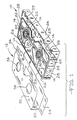
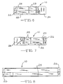
- the tape cassette shown in Figs. 1-8 includes a frame member 10, preferably composed of a durable lightweight thermoplastic material.
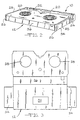
- the frame member 10 is encased by a lightweight flexible sheath 12, preferably composed of paperboard, which is bonded to the frame member 10 to form the cassette shown in Fig. 2.
- the frame member 10 of the video cassette of the present invention is constructed to have the standard outside dimensions designed for use in a standard VHS playback and recording machine.
- the thermoplastic frame member 10 includes open cut-out areas 14 located in the top surface 16 and bottom surface 18 of the frame member 10.
- the cut-out areas 14 are designed to eliminate as much thermoplastic material from the tape cassette as possible, without negatively affecting the structural rigidity of the frame member 10 and the structural support for the tape reels 20.
- the tape reels 20 are supported by thermoplastic cross members 22 extending perpendicularly through the cut-out areas 14.
- the frame member 10 is provided with two distinct thicknesses.
- the protective tape gate area 24, corners 26, and bottom edges 28 are designed to have a thickness of thermoplastic material that is comparable to that found in the "standard" commercial VHS cassette.
- the thermoplastic material of the remaining frame structure is designed to be about 3 ⁇ 56-4 ⁇ 57 x 10 -7 M (.014 to .018 mils)thinner.
- the protective tape gate 24, corners 26 and bottom edges 28, are designed to have the thicker structure in order to provide the necessary strength, integrity and durability to the frame member 10.
- the difference in thickness between the protective tape gate 24, corners 26, bottom edges 28, and the remainder of the frame is equivalent to the thickness of the sheath 12 which is designed to encompass the frame member 10 and bond to the thinner plastic area surrounded by the protective tape gate 24, corners 26, and bottom edges 28.
- up-raised energy director beads 29 which are formed from the same thermoplastic material as the frame member 10.
- the energy director beads 29 are utilized to bond the paperboard sheath member 12 to the frame member 10.
- the sheath member 12 is, preferably, coated on its interior surface with a styrene film or other product known to be compatible with the thermoplastic material of the energy bead 29. In production, the sheath member 12 is positioned over the frame member 10 and ultrasonic vibrations are applied to the composite frame member 10 and sheath member 12.
- the ultrasonic vibrations "melt" the energy beads 29 and causes their material to blend with the styrene coating, thus welding the sheath member 12 to the frame member 10 as the molten blend solidifies.
- other methods of bonding such as adhesives and hot melt gluing, may be used in place of energy director beads 29 and the ultrasonic weld technique.
- the styrene coating serves a secondary purpose of providing a moisture vapor transmission barrier, thereby assisting in maintaining the integrity of the sheath member 12.
- the sheath 12 of the present invention includes a top flap 30, bottom flap 32, end flaps 34, and back flap 36.
- the sheath 12 is patterned to fit on the thin portion of the plastic frame 10, within the edges provided by the protective tape gate 24, corners 26 and top edges 28 of the frame member 10.
- the bottom flap 32 includes holes 38 to allow access to the reels 20 and the top flap 30 is, preferably, composed of solid material.
- Graphics may be applied to the exterior surface of the paperboard sheath 12 shown in Fig. 3 prior to application and bonding of the sheath member 12 to the frame member 10.
- a composite tape cassette having applied graphics is provided.
- the construction of the frame member 10 usually includes a top half A and a bottom half B which are separated to insert the reels 20 and tape (not shown).
- the two halves A and B are fastened together by screws 39.
- the top half A and bottom half B can be designed to include a post and hole friction fit, snap-fit, or any other means of joinder without the need for loose parts, which can be reinforced by the bonding of the sheath member 12 to the frame member 10. This elimination of the need for loose parts such as screws serves to eliminate the cost of the parts, the assembly time required to utilize the parts, as well as eliminate the weight of the screws and further, to hinder the potential for tampering with the tape cassette after manufacture.
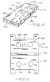
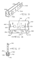
- the tape cassette of the present invention is shown in its preferred embodiment for audio tape cassette use.
- the structure of the audio tape cassette features the same advantages as the video tape cassette referred to in Figs. 1-8.
- the frame member 110 of the audio tape cassette is shown with cut-out areas 114 surrounding the reels 120.
- Cross members 122 support the reels 120 and provide structural rigidity to the frame member 110. All areas of the frame member 110 are of a thin cross section with the exception of the ends 140 and the tape feed area 142.
- the cassette ends 140 and tape feed area 142 are provided with a thicker material to provide structural rigidity and durability to the tape cassette.
- the difference in thickness, preferably, between the cassette ends 140, tape feed area 142 and the remaining portion of the frame member 110 is the thickness of the sheath member 112, approximately .014 to .018 mils.
- a line of energy director beads 129 are provided proximate the cassette ends 140 and tape feed area 142.
- the energy director beads 129 are used in the process of ultrasonic welding and bonding of the sheath 112 to the frame member 110, as described earlier with regard to the video tape embodiment. As with the video tape embodiment, other methods of adhering the sheath member 112 to the frame member 110 may be used.
- the sheath 112 includes a top flap 130, bottom flap 132, and back flap 136.
- the top flap 130 and bottom flap 132 include holes 138 designed to provide access to the reels 120 of the cassette.
- a window 144 may also be provided in the top flap 130 to assist in viewing the tape during running conditions.
- the frame member 110 is provided with a top half AA and a bottom half BB. The two halves are preferably friction fit together and sealed by the bonded sheath member 12, thus eliminating the need for screws to hold the halves together, for the same reasons earlier described with regard to the video cassette.
- the audio tape cassette constructed in accordance with the present invention usually is designed to have a tape feed area 142 that is open and accessible to infiltration by dirt or other foreign objects when not in use.
- a clip member 146 is designed to attache to the cassette and cover the tape feed area 142 in a protective manner.
- the clip member 146 is also designed to provide stability to the cassette so that it can stand upright, horizontally or vertically.
- the clip member 146 is generally constructed of plastic and includes inwardly projecting extrusions 148 designed to mate with indentations 150 located in the frame member 110. The mating of the extrusions 148 with the indentations 150 retain the protective clip member 146 in position.
- An alternative embodiment for the clip member 146 envisions the extension of one side of the member 146 to a location proximate the reels 120 whereby the reels 120 are engaged and locked in place by the extended side of the clip member 146.
Landscapes
- Packaging Of Annular Or Rod-Shaped Articles, Wearing Apparel, Cassettes, Or The Like (AREA)
- Storage Of Web-Like Or Filamentary Materials (AREA)
- Magnetic Record Carriers (AREA)
Claims (17)
- Cassette composite à bande à utiliser avec un dispositif de lecture et d'enregistrement de bande, comportant, en combinaison :un premier élément rigide (110) de bâti définissant la forme d'une telle cassette à bande pour supporter les bobines (120) et une bande, les parois de ladite cassette à bande comprenant des éléments supérieur et inférieur (122) de support, des panneaux latéraux (140) un panneau arrière et un volet (142) de bande, ladite bande et lesdites bobines (120) étant retenues entre ladite paire d'éléments de support opposés (122), lesdits éléments de support (122) étant associés entre eux par des panneaux latéraux opposés (140) et par ledit panneau arrière, lesdits panneaux latéraux définissant en outre des bords supérieurs avec l'élément de support supérieur et des bords inférieurs avec l'élément de support inférieur et des parties d'angle aux jonctions entre lesdits panneaux latéraux (140) et ledit panneau arrière, et ledit volet (142) de bande étant en opposition audit panneau arrière et s'étendant entre lesdits deux panneaux latéraux (140), caractérisée en ce que lesdits éléments de support (122) et ledit panneau arrière définissent une première épaisseur de matière rigide et lesdits angles, éléments latéraux (140), bords supérieurs, bords inférieurs et volet (142) de bande définissent une seconde épaisseur de matière rigide, ladite seconde épaisseur étant supérieure à ladite première épaisseur, et ladite première épaisseur de matière étant moins rigide que ladite seconde épaisseur de matière ; etun élément de fourreau flexible (112) est lié audit élément de bâti (110) sur lesdits éléments de support (122) et ledit panneau arrière pour ajouter de la rigidité et porte contre lesdits bords supérieur et inférieur, ledit volet de bande (142) et lesdits angles pour présenter des surfaces pour l'application directe d'inscriptions graphiques sur cette cassette à bande.
- Cassette à bande selon la revendication 1, caractérisée en ce que ledit élément de bâti (110) est composé d'une matière thermoplastique.
- Cassette à bande selon la revendication 1 ou la revendication 2, caractérisée en ce que ledit élément de fourreau flexible (112) est d'une épaisseur telle que, lorsqu'il est lié à ladite première zone d'épaisseur de matière rigide, il forme une épaisseur composite de matière rigide et d'élément de fourreau sensiblement équivalente à ladite seconde épaisseur de matière rigide, grâce à quoi ledit élément de fourreau flexible est protégé d'une usure prématurée.
- Cassette à bande selon l'une quelconque des revendications 1 à 3, caractérisée en ce que lesdits éléments (112) de support constituent chacun sensiblement une moitié dudit élément de bâti et sont retenus en association par des vis (39).
- Cassette à bande selon l'une quelconque des revendications 1 à 3, caractérisée en ce que lesdits éléments de support (122) forment chacun sensiblement une moitié dudit élément de bâti (110) et sont retenus en association au moyen d'un ajustement à frottement d'une broche et d'un trou.
- Cassette à bande selon l'une quelconque des revendications 1 à 5, caractérisée en ce que l'association desdits éléments de support (122) est renforcée par la liaison dudit élément de fourreau (112) à ladite première zone d'épaisseur.
- Cassette à bande selon l'une quelconque des revendications 1 à 6, caractérisée en ce que ladite première zone d'épaisseur comprend un bourrelet surélevé (129) sensible à l'application d'ultrasons à proximité du périmètre de ladite première zone d'épaisseur, ledit bourrelet surélevé agissant de façon à lier ledit élément de fourreau (112) à ladite première zone d'épaisseur lors d'une exposition à des ultrasons.
- Cassette à bande selon la revendication 9, caractérisée en ce que ledit élément de fourreau (112) comprend un revêtement de matière sur la surface prévue pour être associée audit élément de bâti (110), ledit revêtement de matière agissant de façon à renforcer la liaison entre ledit bourrelet surélevé et ledit élément de fourreau lors d'une exposition à des ultrasons.
- Cassette selon l'une quelconque des revendications 1 à 8, caractérisée en ce que ledit élément de fourreau (112) est lié à ladite première zone d'épaisseur par un adhésif.
- Cassette selon l'une quelconque des revendications 1 à 9, caractérisée en ce que ledit élément de fourreau (112) est lié à ladite première zone d'épaisseur par une colle thermofusible.
- Cassette selon la revendication 1, caractérisée en ce que ledit fourreau (112) est composé de carton.
- Cassette selon l'une quelconque des revendications 1 à 11, comprenant en outre un élément à pince (146) destiné à être attaché à ladite cassette à bande à proximité du volet de bande de cette cassette pour protéger cette bande.
- Cassette selon la revendication 12, caractérisée en ce que ledit élément à pince (146) comprend un élément de retenue de moyeu destiné à engager les bobines de cette cassette et à bloquer ces bobines pour empêcher une rotation non voulue.
- Cassette à bande selon l'une quelconque des revendications 1 à 13, caractérisée en ce que ladite première zone d'épaisseur présente une surface plane plus grande sur chacun desdits éléments de support (122), ladite grande surface plane s'étendant entre lesdits panneaux latéraux, ledit panneau arrière et ledit volet de bande (142).
- Casette à bande selon la revendication 14, caractérisée en ce que lesdites surfaces planes plus grandes comprennent chacune des zones découpées (114) dans lesquelles la matière rigide est enlevée et des éléments transversaux de cette matière rigide s'étendent à travers lesdites zones découpées pour retenir et supporter cette bande et ces bobines (120).
- Cassette à bande selon l'une quelconque des revendications 1 à 16, caractérisée en ce que ledit élément flexible de fourreau comprend un revêtement de matière destiné à constituer une barrière contre la transmission d'humidité et de vapeur pour ledit élément de fourreau (112).
- Cassette composite à bande à utiliser avec un dispositif de lecture et d'enregistrement de bande comportant, en combinaison :un élément de bâti rigide (10) définissant les parois de ladite cassette à bande pour supporter les bobines et une bande, lesdites parois de la cassette à bande comprenant des éléments de support supérieur et inférieur (22), des panneaux latéraux, un panneau arrière et un volet (24) de bande, ladite bande et lesdites bobines étant retenues entre ladite paire d'éléments opposés (22) de support, lesdits éléments de support Étant associés l'un à l'autre par l'intermédiaire de panneaux latéraux opposés et lesdits panneaux arrière, lesdits panneaux latéraux définissant en outre des bords supérieurs avec l'élément supérieur de support et des bords inférieurs avec l'élément inférieur de support et des parties d'angle (26) aux jonctions entre lesdits panneaux latéraux et ledit panneau arrière, et ledit volet de bande (24) en opposition audit panneau arrière et s'étendant entre lesdits deux panneaux latéraux, caractérisée en ce que lesdits éléments de support, éléments latéraux, bords supérieurs et panneau arrière sont formés d'une première épaisseur de matière rigide et lesdits angles (26), bords inférieurs (28) et volet de bande (24) sont formés d'une seconde épaisseur de matière rigide, ladite seconde épaisseur étant supérieure à ladite première épaisseur, et ladite première épaisseur de matière étant moins rigide que ladite seconde épaisseur de matière ; etun élément de fourreau flexible (12) est lié audit élément de bâti (10) au-dessus desdits éléments de support, éléments latéraux et panneau arrière pour ajouter de la rigidité, et porte contre lesdits bords inférieurs, volet de bande et angles pour présenter des surfaces pour l'application directe d'inscriptions graphiques sur une telle cassette à bande.
Applications Claiming Priority (3)
| Application Number | Priority Date | Filing Date | Title |
|---|---|---|---|
| US897233 | 1978-04-17 | ||
| US07/897,233 US5311388A (en) | 1992-06-11 | 1992-06-11 | Composite tape cassette |
| PCT/US1993/005579 WO1993026009A1 (fr) | 1992-06-11 | 1993-06-08 | Cassette composite de bande magnetique |
Publications (3)
| Publication Number | Publication Date |
|---|---|
| EP0689710A4 EP0689710A4 (fr) | 1995-09-26 |
| EP0689710A1 EP0689710A1 (fr) | 1996-01-03 |
| EP0689710B1 true EP0689710B1 (fr) | 1997-09-10 |
Family
ID=25407586
Family Applications (1)
| Application Number | Title | Priority Date | Filing Date |
|---|---|---|---|
| EP93916492A Expired - Lifetime EP0689710B1 (fr) | 1992-06-11 | 1993-06-08 | Cassette composite de bande magnetique |
Country Status (8)
| Country | Link |
|---|---|
| US (2) | US5311388A (fr) |
| EP (1) | EP0689710B1 (fr) |
| JP (1) | JPH07507897A (fr) |
| AT (1) | ATE158100T1 (fr) |
| CA (1) | CA2134676C (fr) |
| DE (1) | DE69313874T2 (fr) |
| ES (1) | ES2108291T3 (fr) |
| WO (1) | WO1993026009A1 (fr) |
Families Citing this family (12)
| Publication number | Priority date | Publication date | Assignee | Title |
|---|---|---|---|---|
| US5311388A (en) * | 1992-06-11 | 1994-05-10 | Mclaren Edwin C | Composite tape cassette |
| US5482222A (en) * | 1993-01-07 | 1996-01-09 | V-Lite Corporation | Lightweight solid-core video cassette cartridge |
| US5568898A (en) * | 1993-11-03 | 1996-10-29 | Lcv Associates | Wrap around label |
| US5568899A (en) * | 1995-05-05 | 1996-10-29 | V-Lite Corporation | Lightweight video cassette cartridge |
| US5584440A (en) * | 1995-11-06 | 1996-12-17 | V-Lite Corporation | Lightweight video cassette cartridge |
| US5894268A (en) * | 1998-01-28 | 1999-04-13 | Mclaren; Edwin C. | Cassette and security strip therefor |
| US6186208B1 (en) * | 1998-05-29 | 2001-02-13 | Intellishell, Inc. | Automatic cassette wrapping and assembly machine |
| EP1105874A4 (fr) * | 1998-08-14 | 2003-03-12 | Verbatim Corp | Cartouche de bande de grande capacite haute performance |
| US6390402B2 (en) | 1998-08-14 | 2002-05-21 | Verbatim Corporation | Tape cartridge having lockout features |
| US6045079A (en) * | 1998-08-14 | 2000-04-04 | Verbatim Corporation | Tape cartridge having a large door and pivotally mounted write protect arm |
| US7215998B2 (en) * | 2003-01-06 | 2007-05-08 | Medtronic, Inc. | Synchronous pacemaker with AV interval optimization |
| US7162300B2 (en) * | 2003-01-13 | 2007-01-09 | Medtronic, Inc. | Synchronized atrial anti-tachy pacing system and method |
Family Cites Families (10)
| Publication number | Priority date | Publication date | Assignee | Title |
|---|---|---|---|---|
| DE2951951A1 (de) * | 1979-12-22 | 1981-07-09 | Basf Ag, 6700 Ludwigshafen | Bandkassette fuer streifen- oder bandfoermige aufzeichnungstraeger, insbesondere magnetbaender, sowie kassettengehaeuse und schutz-/haltehuelle fuer aufgewickelte aufzeichnungstraeger |
| US4352578A (en) * | 1980-09-08 | 1982-10-05 | International Business Machines Corporation | Paperboard ribbon cartridge |
| WO1988002916A1 (fr) * | 1986-10-20 | 1988-04-21 | John Michael Woodbury | Cassettes video |
| US4891712A (en) * | 1987-12-03 | 1990-01-02 | Nfo Research, Inc. | Method of conducting marketing research by using video tape productions |
| US4883176A (en) * | 1989-05-15 | 1989-11-28 | Container Corporation Of America | Paperboard video cassette housing |
| IL96433A (en) * | 1989-11-22 | 1994-11-28 | Klupt Carle D | Video tapes, packaging for them and a process for producing videotape with integral mail packaging |
| US4978009A (en) * | 1989-11-27 | 1990-12-18 | William Pany | Video cassette box with removable panel |
| US4969612A (en) * | 1989-12-04 | 1990-11-13 | Thomas Robert G | Cassette formed from a bendable material |
| US5103978A (en) * | 1990-06-14 | 1992-04-14 | Secor Nancy A | Covers for videocassettes, videocassette jackets and similar like articles |
| US5311388A (en) * | 1992-06-11 | 1994-05-10 | Mclaren Edwin C | Composite tape cassette |
-
1992
- 1992-06-11 US US07/897,233 patent/US5311388A/en not_active Expired - Fee Related
-
1993
- 1993-06-08 JP JP6501730A patent/JPH07507897A/ja active Pending
- 1993-06-08 AT AT93916492T patent/ATE158100T1/de not_active IP Right Cessation
- 1993-06-08 DE DE69313874T patent/DE69313874T2/de not_active Expired - Fee Related
- 1993-06-08 ES ES93916492T patent/ES2108291T3/es not_active Expired - Lifetime
- 1993-06-08 EP EP93916492A patent/EP0689710B1/fr not_active Expired - Lifetime
- 1993-06-08 WO PCT/US1993/005579 patent/WO1993026009A1/fr not_active Ceased
- 1993-06-08 CA CA002134676A patent/CA2134676C/fr not_active Expired - Fee Related
-
1994
- 1994-01-27 US US08/188,209 patent/US5414582A/en not_active Expired - Fee Related
Also Published As
| Publication number | Publication date |
|---|---|
| ATE158100T1 (de) | 1997-09-15 |
| CA2134676A1 (fr) | 1993-12-23 |
| JPH07507897A (ja) | 1995-08-31 |
| EP0689710A4 (fr) | 1995-09-26 |
| WO1993026009A1 (fr) | 1993-12-23 |
| DE69313874D1 (de) | 1997-10-16 |
| EP0689710A1 (fr) | 1996-01-03 |
| US5414582A (en) | 1995-05-09 |
| US5311388A (en) | 1994-05-10 |
| DE69313874T2 (de) | 1998-04-02 |
| CA2134676C (fr) | 1996-08-06 |
| ES2108291T3 (es) | 1997-12-16 |
Similar Documents
| Publication | Publication Date | Title |
|---|---|---|
| US5311388A (en) | Composite tape cassette | |
| JPS58130473A (ja) | 情報記憶媒体の収納ケ−ス | |
| US6076989A (en) | Casing board with transparent cover | |
| WO1988008196A1 (fr) | Videocassette | |
| US4763218A (en) | Video tape cassette with internal tape erasing means | |
| US5201476A (en) | Welded video cassette | |
| US5199662A (en) | Limited use combined mailer and video cassette and method of forming same | |
| EP0502077B1 (fr) | Cassette video d'usage limite a emballage d'expedition integre | |
| US6186319B1 (en) | Double VHS storage container | |
| US5199663A (en) | Limited use video cassette | |
| US6302344B1 (en) | Lightweight video cassette | |
| JP2592600Y2 (ja) | テープカセット | |
| JP2576845Y2 (ja) | テープカセット | |
| JPS6341616Y2 (fr) | ||
| JPH07242260A (ja) | レンタル商品の盗難防止装置 | |
| JP2602887Y2 (ja) | 包装容器 | |
| JP3307487B2 (ja) | 光ディスク収納ケース | |
| JP3000841U (ja) | レンタルショップ用ビデオケース | |
| JP3006501U (ja) | レンタルブックカバー | |
| KR930000499Y1 (ko) | 카세트 및 비디오 테잎 케이스 | |
| JPH0636543Y2 (ja) | ディスクカートリッジ | |
| KR930002284Y1 (ko) | 조립완구를 겸할 수 있는 비디오 테이프 카세트의 조립셋트 | |
| JP3319590B2 (ja) | ディスク収納体及びディスク収納体を綴じた本 | |
| JPH063891U (ja) | ビデオテープ等のケース | |
| KR970008131A (ko) | 녹화정보 기록매체를 갖춘 비디오카세트테이프 |
Legal Events
| Date | Code | Title | Description |
|---|---|---|---|
| A4 | Supplementary search report drawn up and despatched | ||
| AK | Designated contracting states |
Kind code of ref document: A4 Designated state(s): AT BE CH DE DK ES FR GB GR IE IT LI LU MC NL PT SE |
|
| PUAI | Public reference made under article 153(3) epc to a published international application that has entered the european phase |
Free format text: ORIGINAL CODE: 0009012 |
|
| 17P | Request for examination filed |
Effective date: 19941107 |
|
| AK | Designated contracting states |
Kind code of ref document: A1 Designated state(s): AT BE CH DE DK ES FR GB GR IE IT LI LU MC NL PT SE |
|
| GRAG | Despatch of communication of intention to grant |
Free format text: ORIGINAL CODE: EPIDOS AGRA |
|
| 17Q | First examination report despatched |
Effective date: 19970110 |
|
| GRAH | Despatch of communication of intention to grant a patent |
Free format text: ORIGINAL CODE: EPIDOS IGRA |
|
| GRAH | Despatch of communication of intention to grant a patent |
Free format text: ORIGINAL CODE: EPIDOS IGRA |
|
| GRAA | (expected) grant |
Free format text: ORIGINAL CODE: 0009210 |
|
| AK | Designated contracting states |
Kind code of ref document: B1 Designated state(s): AT BE CH DE DK ES FR GB GR IE IT LI LU MC NL PT SE |
|
| PG25 | Lapsed in a contracting state [announced via postgrant information from national office to epo] |
Ref country code: LI Free format text: LAPSE BECAUSE OF FAILURE TO SUBMIT A TRANSLATION OF THE DESCRIPTION OR TO PAY THE FEE WITHIN THE PRESCRIBED TIME-LIMIT Effective date: 19970910 Ref country code: GR Free format text: LAPSE BECAUSE OF FAILURE TO SUBMIT A TRANSLATION OF THE DESCRIPTION OR TO PAY THE FEE WITHIN THE PRESCRIBED TIME-LIMIT Effective date: 19970910 Ref country code: DK Free format text: LAPSE BECAUSE OF NON-PAYMENT OF DUE FEES Effective date: 19970910 Ref country code: CH Free format text: LAPSE BECAUSE OF FAILURE TO SUBMIT A TRANSLATION OF THE DESCRIPTION OR TO PAY THE FEE WITHIN THE PRESCRIBED TIME-LIMIT Effective date: 19970910 Ref country code: BE Effective date: 19970910 Ref country code: AT Effective date: 19970910 |
|
| REF | Corresponds to: |
Ref document number: 158100 Country of ref document: AT Date of ref document: 19970915 Kind code of ref document: T |
|
| REG | Reference to a national code |
Ref country code: CH Ref legal event code: EP |
|
| REF | Corresponds to: |
Ref document number: 69313874 Country of ref document: DE Date of ref document: 19971016 |
|
| ET | Fr: translation filed | ||
| ITF | It: translation for a ep patent filed | ||
| PG25 | Lapsed in a contracting state [announced via postgrant information from national office to epo] |
Ref country code: SE Effective date: 19971210 Ref country code: PT Effective date: 19971210 |
|
| REG | Reference to a national code |
Ref country code: ES Ref legal event code: FG2A Ref document number: 2108291 Country of ref document: ES Kind code of ref document: T3 |
|
| REG | Reference to a national code |
Ref country code: IE Ref legal event code: FG4D Free format text: 76435 |
|
| REG | Reference to a national code |
Ref country code: CH Ref legal event code: PL |
|
| PG25 | Lapsed in a contracting state [announced via postgrant information from national office to epo] |
Ref country code: LU Free format text: LAPSE BECAUSE OF NON-PAYMENT OF DUE FEES Effective date: 19980608 Ref country code: IE Free format text: LAPSE BECAUSE OF NON-PAYMENT OF DUE FEES Effective date: 19980608 |
|
| PLBE | No opposition filed within time limit |
Free format text: ORIGINAL CODE: 0009261 |
|
| STAA | Information on the status of an ep patent application or granted ep patent |
Free format text: STATUS: NO OPPOSITION FILED WITHIN TIME LIMIT |
|
| 26N | No opposition filed | ||
| PG25 | Lapsed in a contracting state [announced via postgrant information from national office to epo] |
Ref country code: MC Free format text: LAPSE BECAUSE OF NON-PAYMENT OF DUE FEES Effective date: 19981231 |
|
| REG | Reference to a national code |
Ref country code: IE Ref legal event code: MM4A |
|
| PGFP | Annual fee paid to national office [announced via postgrant information from national office to epo] |
Ref country code: FR Payment date: 20011002 Year of fee payment: 9 |
|
| PGFP | Annual fee paid to national office [announced via postgrant information from national office to epo] |
Ref country code: GB Payment date: 20011004 Year of fee payment: 9 Ref country code: DE Payment date: 20011004 Year of fee payment: 9 |
|
| PGFP | Annual fee paid to national office [announced via postgrant information from national office to epo] |
Ref country code: NL Payment date: 20011009 Year of fee payment: 9 Ref country code: ES Payment date: 20011009 Year of fee payment: 9 |
|
| REG | Reference to a national code |
Ref country code: GB Ref legal event code: IF02 |
|
| PG25 | Lapsed in a contracting state [announced via postgrant information from national office to epo] |
Ref country code: GB Free format text: LAPSE BECAUSE OF NON-PAYMENT OF DUE FEES Effective date: 20020608 |
|
| PG25 | Lapsed in a contracting state [announced via postgrant information from national office to epo] |
Ref country code: ES Free format text: LAPSE BECAUSE OF NON-PAYMENT OF DUE FEES Effective date: 20020609 |
|
| PG25 | Lapsed in a contracting state [announced via postgrant information from national office to epo] |
Ref country code: NL Free format text: LAPSE BECAUSE OF NON-PAYMENT OF DUE FEES Effective date: 20030101 Ref country code: DE Free format text: LAPSE BECAUSE OF NON-PAYMENT OF DUE FEES Effective date: 20030101 |
|
| GBPC | Gb: european patent ceased through non-payment of renewal fee |
Effective date: 20020608 |
|
| PG25 | Lapsed in a contracting state [announced via postgrant information from national office to epo] |
Ref country code: FR Free format text: LAPSE BECAUSE OF NON-PAYMENT OF DUE FEES Effective date: 20030228 |
|
| NLV4 | Nl: lapsed or anulled due to non-payment of the annual fee |
Effective date: 20030101 |
|
| REG | Reference to a national code |
Ref country code: FR Ref legal event code: ST |
|
| REG | Reference to a national code |
Ref country code: ES Ref legal event code: FD2A Effective date: 20030711 |
|
| PG25 | Lapsed in a contracting state [announced via postgrant information from national office to epo] |
Ref country code: IT Free format text: LAPSE BECAUSE OF NON-PAYMENT OF DUE FEES;WARNING: LAPSES OF ITALIAN PATENTS WITH EFFECTIVE DATE BEFORE 2007 MAY HAVE OCCURRED AT ANY TIME BEFORE 2007. THE CORRECT EFFECTIVE DATE MAY BE DIFFERENT FROM THE ONE RECORDED. Effective date: 20050608 |