EP0689714B1 - Reacteur a eau sous pression dans lequel la pression de distribution de caloporteur est adaptee aux faisceaux individuels de crayons combustibles - Google Patents
Reacteur a eau sous pression dans lequel la pression de distribution de caloporteur est adaptee aux faisceaux individuels de crayons combustibles Download PDFInfo
- Publication number
- EP0689714B1 EP0689714B1 EP94910324A EP94910324A EP0689714B1 EP 0689714 B1 EP0689714 B1 EP 0689714B1 EP 94910324 A EP94910324 A EP 94910324A EP 94910324 A EP94910324 A EP 94910324A EP 0689714 B1 EP0689714 B1 EP 0689714B1
- Authority
- EP
- European Patent Office
- Prior art keywords
- plate
- fuel
- pressure vessel
- coolant
- throttle
- Prior art date
- Legal status (The legal status is an assumption and is not a legal conclusion. Google has not performed a legal analysis and makes no representation as to the accuracy of the status listed.)
- Revoked
Links
- 239000000446 fuel Substances 0.000 title claims abstract description 107
- 239000002826 coolant Substances 0.000 title claims abstract description 40
- XLYOFNOQVPJJNP-UHFFFAOYSA-N water Substances O XLYOFNOQVPJJNP-UHFFFAOYSA-N 0.000 title claims abstract description 11
- 230000006978 adaptation Effects 0.000 claims description 3
- 230000000712 assembly Effects 0.000 description 10
- 238000000429 assembly Methods 0.000 description 10
- 125000006850 spacer group Chemical group 0.000 description 10
- 230000006835 compression Effects 0.000 description 2
- 238000007906 compression Methods 0.000 description 2
- 238000001816 cooling Methods 0.000 description 2
- 238000005452 bending Methods 0.000 description 1
- 238000009835 boiling Methods 0.000 description 1
- 238000010276 construction Methods 0.000 description 1
- 238000011161 development Methods 0.000 description 1
- 230000018109 developmental process Effects 0.000 description 1
- 238000010586 diagram Methods 0.000 description 1
- 230000000694 effects Effects 0.000 description 1
- 230000004992 fission Effects 0.000 description 1
- 238000000034 method Methods 0.000 description 1
- 230000005855 radiation Effects 0.000 description 1
- 239000002915 spent fuel radioactive waste Substances 0.000 description 1
- 230000006641 stabilisation Effects 0.000 description 1
- 238000011105 stabilization Methods 0.000 description 1
- 230000007704 transition Effects 0.000 description 1
Images


Classifications
-
- G—PHYSICS
- G21—NUCLEAR PHYSICS; NUCLEAR ENGINEERING
- G21C—NUCLEAR REACTORS
- G21C3/00—Reactor fuel elements and their assemblies; Selection of substances for use as reactor fuel elements
- G21C3/30—Assemblies of a number of fuel elements in the form of a rigid unit
- G21C3/32—Bundles of parallel pin-, rod-, or tube-shaped fuel elements
- G21C3/322—Means to influence the coolant flow through or around the bundles
-
- Y—GENERAL TAGGING OF NEW TECHNOLOGICAL DEVELOPMENTS; GENERAL TAGGING OF CROSS-SECTIONAL TECHNOLOGIES SPANNING OVER SEVERAL SECTIONS OF THE IPC; TECHNICAL SUBJECTS COVERED BY FORMER USPC CROSS-REFERENCE ART COLLECTIONS [XRACs] AND DIGESTS
- Y02—TECHNOLOGIES OR APPLICATIONS FOR MITIGATION OR ADAPTATION AGAINST CLIMATE CHANGE
- Y02E—REDUCTION OF GREENHOUSE GAS [GHG] EMISSIONS, RELATED TO ENERGY GENERATION, TRANSMISSION OR DISTRIBUTION
- Y02E30/00—Energy generation of nuclear origin
- Y02E30/30—Nuclear fission reactors
-
- Y—GENERAL TAGGING OF NEW TECHNOLOGICAL DEVELOPMENTS; GENERAL TAGGING OF CROSS-SECTIONAL TECHNOLOGIES SPANNING OVER SEVERAL SECTIONS OF THE IPC; TECHNICAL SUBJECTS COVERED BY FORMER USPC CROSS-REFERENCE ART COLLECTIONS [XRACs] AND DIGESTS
- Y10—TECHNICAL SUBJECTS COVERED BY FORMER USPC
- Y10S—TECHNICAL SUBJECTS COVERED BY FORMER USPC CROSS-REFERENCE ART COLLECTIONS [XRACs] AND DIGESTS
- Y10S376/00—Induced nuclear reactions: processes, systems, and elements
- Y10S376/90—Particular material or material shapes for fission reactors
- Y10S376/901—Fuel
Definitions
- the invention relates to a pressurized water reactor with the features specified in the preamble of claim 1.
- Fuel elements of pressurized water reactors contain a bundle of fuel rods which are arranged around control rod flow tubes, this fuel rod bundle in the head of the fuel element being covered by a cover plate.
- a large number of fuel elements of this type stand side by side on a grate at the bottom of the pressure vessel and are supported with their head parts on the mesh of a grid plate.
- a collecting space is formed in the interior of the pressure vessel, into which structures protrude on the top of the grid plate. This collecting space contains a side outlet, for example one or more outlet connections for a coolant flow.
- This coolant stream is guided by appropriate means from an inlet in the pressure vessel to the grate at the bottom of the pressure vessel, is distributed there to the individual fuel assemblies, then flows along the fuel rods and exits through openings in the fuel element cover plates to pass through the mesh of the grid plate through to enter the collecting room.
- the grate on the bottom of the pressure vessel can already carry throttle plates or inserts in order to distribute the coolant flow evenly over the entire cross section of the pressure vessel.
- the gaps between the fuel rods and guide tubes of a fuel assembly are connected to one another and to the interstices of adjacent fuel assemblies, so that flows of coolant directed across the fuel assemblies can occur in the pressure vessel.
- This can be desirable in order to achieve a thorough mixing between hotter and cooler areas of the coolant, for which purpose spacers with corresponding deflection devices on different axial planes of the fuel assembly can be provided.
- spacers are required anyway in order to fix the lateral spacing of the fuel rods, but besides these spacers supporting the fuel rods, separate grid structures can also be provided for holding further mixing devices on the fuel elements.
- the structures that protrude from the top of the grid plate into the dome of the pressure vessel are necessary, for example, to mechanically support the grid plate and to accommodate the control rods that can be inserted into the control rod guide tubes.
- the partial flows of the coolant, into which the coolant is divided at the lower grate and which emerge after flowing through the individual fuel elements through the individual meshes of the grid plate, must therefore overcome an individual flow resistance on their way to the outlet, due to the length of the respective flow path and the obstacles standing in this way is determined. Therefore, a pressure occurs in the coolant as it passes through the passage openings of the plates, which is inhomogeneously distributed over the cross section of the pressure vessel.
- the coolant When passing through the cover plates, the coolant suffers a back pressure, which due to the geometrical arrangement of the structures on the cover plate and the lateral outlet can be different for each fuel element and already in the axial zone of the pressure vessel in which the fuel rods are seated, to pressure differences and resulting cross flows.
- the coolant can be guided vertically through the collecting space in the dome of the pressure vessel and discharged through appropriate vertical outlet connections that take into account the geometry of the structures on the grid plate.
- the invention is therefore based on the object, in reactors of the type mentioned in the interior of the reactor pressure vessel, an inhomogeneous flow velocity with undesirable cross-flows in the axial region in which the fuel rods are seated, through an individual adaptation of the flow conditions in the region of the fuel element heads and the latter Avoid heads supporting grid plate.
- This task is solved by an individual throttling of the coolant flow when passing through the individual fuel element heads or at the latest when passing through the grid plate.
- Such an individual throttling when passing through the head of the fuel assembly is achieved by the features of claim 1, a corresponding individual throttling when passing through the mesh of the grid plate by the features of claim 7.
- a throttle plate can be fastened in the head of a plurality of fuel elements (in particular in each case above the cover plate), which contains one or more throttle openings for the individual adjustment of the pressure in the coolant which flows through the head of the respective fuel element.
- a throttle plate can also carry throttle elements, each with one or more passage openings, which bring about the individual adjustment of the pressure in the coolant which flows through the head of these fuel elements.
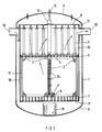
- the fuel assembly zone is laterally surrounded by a core shroud 17 within a core barrel 18, so that the coolant flowing in through an inlet 16 leads to a flow skirt 19 at the bottom of the Pressure vessel is directed.
- the coolant then enters the bottom of a fuel assembly from below through the lower grate 7 and flows essentially vertically along the fuel rods to the passage openings of a cover plate which covers the corresponding fuel assembly in the head of the fuel assembly.
- the coolant then passes through the fuel assembly head 3 and the mesh 4 of the grid plate 5 from the respective fuel assembly into the collecting space 10, in which it is deflected to one or more lateral outlet connections (outlet 20).
- FIG. 2 shows the horizontal components of the coolant flow that occur within a quadrant of the core.
- the fuel assemblies are arranged in rows 22, the alignment lines of which Figure 2 shows.
- Columns 23 are formed between the individual fuel element rows, the coolant being able to pass from one fuel element row into the other largely unimpeded through the columns 23.
- These cross-flows are generated by pressure differences below the grid plate, these pressure differences being caused by the back pressure that the coolant suffers from the flow obstacles that occur face him in the collecting room after passing through the grid plate and on the way to the outlet.
- FIG. 1 shows some positions 26 at which, for example, strong changes in the flow and the direction of flow cause turbulence and special mechanical loads.
- the coolant flow which is already distributed fairly evenly over the various areas of the core cross section on a lower grid plate or the lower grate 7, is guided individually in the individual fuel elements (the fuel element feet contain funnel-shaped, laterally closed transition pieces and the fuel rod bundle is from a fuel assembly box ("water canal") surrounded on the side), the feet of conventional pressurized water fuel elements consist only of a frame that is open on the side and the fuel elements are not surrounded by a channel on the side.
- the invention therefore provides that in the fuel elements of a pressurized water reactor by appropriate throttling of the coolant flow at the entry into the collecting space 10 to force uniform pressure conditions, so that the cause of the above-mentioned cross currents are eliminated below the grid plate.
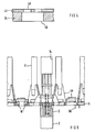
- FIG. 3 shows a cross section through the head region of a fuel assembly.
- the upper caps 30 of the individual fuel rods 31, in which a compensation space for the gaseous fission products generated by the nuclear processes is created by compression springs, are held in the mesh of a spacer 24.
- the spacers themselves are carried by control rod guide tubes 32, which are fastened to a cover plate 34 by a screwed nut 33.
- a similar attachment is also provided between the guide tubes and the fuel element feet 6, so that the cover plate carried by a frame 35 of the fuel element head, the guide tubes with the spacers and the foot part form a supporting skeleton for the fuel rods.
- the frame 35 of the fuel assembly head with the associated cover plate 34 is supported on the grid plate 5 by compression springs 36.
- FIG. 4 shows that the cover plate 34 has passage openings 40 which are advantageously arranged in such a way that they lie above the gaps that arise between the individual fuel rods 31.
- a throttle plate 41 is detachably fastened at least in the head of several fuel assemblies.
- This throttle plate can in particular rest on the cover plate, this throttle plate 41 in FIG. 3 via the nut 33 of some control rod guide tubes 32 is screwed to the cover plate 34.
- FIG. 5 shows that the cover plate 34 and throttle plate 41 are advantageously held in the head of the fuel assembly via common hold-down devices, for example the springs 36.
- the throttle plate contains throttle openings 43, which overall advantageously have a smaller cross-sectional area than the through openings 40 of the cover plate 34 and lie over these through openings 40 with the largest part of their cross-sectional area.
- the arrangement of the individual throttle plates and the dimensioning of their passage openings are individually adapted to the position of the respective fuel element on the grid plate so that when the coolant passes through the fuel element heads of all fuel elements, for example, there is a uniform backflow everywhere, i.e. no horizontal pressure changes occur.
- it can also be provided by appropriate design of the throttle plates to maintain a certain uniform pattern of weak cross flows to increase the mixing of the coolant.
- the grid plate 5 can carry on its underside centering pins 60 ("fuel assembly alignment pin") which engage in corresponding bores in the head parts 3 of the fuel elements in order to hold the fuel element heads on the respective meshes of the grid plate 5 to position.
- the top of the grid plate 5 carries the control rod guides 14, the support pillars 11 and support structures 11 'for the fuel assembly heads.
- the webs of the grid plate 5 form individual meshes, throttle elements 61 being inserted into at least several of these meshes.
- These throttling elements can be used together with new fuel elements when replacing spent fuel elements in order to equalize the pressure in the coolant which emerges from the head of the new fuel elements supported on these meshes, with the pressure, who ruled the old fuel element. If fuel elements that have not yet completely burned off are moved to another place in the reactor core during such a fuel element change, the throttle elements, which are advantageously designed as inserts for the lattice mesh, can be put back in their old place.
- the throttle plates or throttle elements according to the invention thus influence the back pressure occurring in the coolant below the grid plate so that practically no horizontal pressure differences occur below this grid plate or at least these pressure differences lead to a desired distribution of the coolant when entering the collecting space.
- they can contribute to the stabilization of the desired flow, which also makes the thermodynamic and hydrodynamic conditions in the reactor core easier to calculate and control.
Landscapes
- Physics & Mathematics (AREA)
- Engineering & Computer Science (AREA)
- Plasma & Fusion (AREA)
- General Engineering & Computer Science (AREA)
- High Energy & Nuclear Physics (AREA)
- Monitoring And Testing Of Nuclear Reactors (AREA)
- Structure Of Emergency Protection For Nuclear Reactors (AREA)
Abstract
Claims (8)
- Réacteur à eau sous pression, comportant une pluralité d'assemblages combustibles (2), qui sont disposés les uns à côté des autres à l'intérieur d'une cuve (1) sous pression sur une grille (7) au fond (8) de la cuve sous pression et qui en outre comporte chacun un faisceau de crayons (30) combustibles disposé autour de tubes-guides (32) de barre de commande, et qui s'appuient sur des mailles (4) d'une plaque (5) de grille par une tête (3) portant une plaque (34) de recouvrement recouvrant le faisceau, dans lequel il est formé, au-dessus de la plaque de grille à l'intérieur de la cuve (1) sous pression, une chambre (10) collectrice, dans laquelle des superstructures (11, 14) font saillies du côté supérieur de la plaque (5) de grille et qui comporte une sortie (20) latérale, et dans lequel la cuve (1) sous pression comporte des moyens (17, 18, 19) qui dévient un courant de fluide de refroidissement arrivant par une entrée (16) dans la cuve sous pression pour le faire passer à travers la grille (7), le répartissent sur les assemblage combustibles et le font passer le long des crayons combustibles et par des ouvertures (40) de traversée ménagées dans la plaque de recouvrement des assemblages combustibles et par des mailles (4) de la plaque de grille jusque dans la chambre (10) collectrice, caractérisé en ce que, il est fixé dans la tête (3) de plusieurs assemblages combustibles, une plaque (41) d'étranglement comportant des ouvertures (42) d'étranglement pour l'adaptation individuelle de la pression dans la tête du fluide de refroidissement s'écoulant dans chacun des assemblages combustibles.
- Réacteur suivant la revendication 1, caractérisé en ce que les ouvertures (42) d'étranglement de la plaque (41) d'étranglement ont une section transversale plus petite que celle des ouvertures (40) de traversée de la plaque (34) de recouvrement et reposent par leur partie la plus grande de leur surface transversale sur les ouvertures de traversée de la plaque de recouvrement.
- Réacteur suivant la revendication 1 ou 2, caractérisé en ce que la plaque d'étranglement est fixée de manière amovible dans la tête d'assemblage combustible.
- Réacteur suivant l'une des revendications 1 à 3, caractérisé en ce que la plaque (41) d'étranglement et la plaque (34) de recouvrement sont vissées en commun à une extrémité supérieure de tube-guide de barres de commande.
- Réacteur suivant l'une des revendications 1 à 3, caractérisé en ce que la plaque de recouvrement et la plaque d'étranglement sont maintenues dans la tête de l'assemblage combustible par l'intermédiaire d'un serre-flanc commun.
- Réacteur suivant l'une des revendications 1 à 5, caractérisé en ce que la plaque (41) d'étranglement est disposée au-dessus de la plaque (34) de recouvrement.
- Réacteur à eau sous pression comportant une pluralité d'assemblages combustibles (2), qui se trouvent les uns à côté des autres à l'intérieur d'une cuve (1) sous pression sur une grille (7) au fond (8) de la cuve sous pression, qui comporte chacun un faisceau de crayons (2) combustibles et qui s'appuient chacun par une tête sur la maille (4) d'une plaque (5) de grille, dans lequel il est formé au-dessus de la plaque (5) de grille à l'intérieur de la cuve sous pression une chambre (10) collectrice, dans laquelle des superstructures (11, 14) font saillies du côté supérieur de la plaque de grille et qui comportent une sortie (20) latérale pour du fluide de refroidissement, et dans lequel la cuve (1) sous pression comporte des moyens qui dévient un courant de fluide arrivant d'une entrée (16) dans la cuve sous pression, le répartissent par la grille (7) dans les assemblages (3) combustibles individuels et le conduisent le long des crayons combustibles et par la tête de l'assemblage combustible et les mailles de la plaque de grille jusque dans la chambre (10) collectrice, caractérisé en ce que plusieurs mailles (4) de grille portent des éléments (61) d'étranglement comportant chacun une ou plusieurs ouvertures de traversée pour l'adaptation individuelle de la pression dans le fluide de refroidissement sortant de la tête des assemblages combustibles supportés sur ces mailles de grille.
- Réacteur suivant la revendication 7, caractérisé par des inserts (61) d'étranglement insérés dans des mailles de grille.
Applications Claiming Priority (3)
| Application Number | Priority Date | Filing Date | Title |
|---|---|---|---|
| DE4308364A DE4308364A1 (de) | 1993-03-16 | 1993-03-16 | Druckwasserreaktor mit individuell angepaßter Druckverteilung im Kühlmittel |
| DE4308364 | 1993-03-16 | ||
| PCT/DE1994/000256 WO1994022146A1 (fr) | 1993-03-16 | 1994-03-04 | Reacteur a eau sous pression dans lequel la pression de distribution de caloporteur est adaptee aux faisceaux individuels de crayons combustibles |
Publications (2)
| Publication Number | Publication Date |
|---|---|
| EP0689714A1 EP0689714A1 (fr) | 1996-01-03 |
| EP0689714B1 true EP0689714B1 (fr) | 1997-06-11 |
Family
ID=6482957
Family Applications (1)
| Application Number | Title | Priority Date | Filing Date |
|---|---|---|---|
| EP94910324A Revoked EP0689714B1 (fr) | 1993-03-16 | 1994-03-04 | Reacteur a eau sous pression dans lequel la pression de distribution de caloporteur est adaptee aux faisceaux individuels de crayons combustibles |
Country Status (6)
| Country | Link |
|---|---|
| US (1) | US5617457A (fr) |
| EP (1) | EP0689714B1 (fr) |
| JP (1) | JPH08507861A (fr) |
| KR (1) | KR960701450A (fr) |
| DE (2) | DE4308364A1 (fr) |
| WO (1) | WO1994022146A1 (fr) |
Families Citing this family (6)
| Publication number | Priority date | Publication date | Assignee | Title |
|---|---|---|---|---|
| US20040096026A1 (en) * | 2002-11-18 | 2004-05-20 | Hwang Choe | Apparatus and methods for optimizing reactor core coolant flow distributions |
| DE10358829B3 (de) * | 2003-12-16 | 2005-06-16 | Framatome Anp Gmbh | Brennelement für einen Druckwasserkernreaktor |
| CA2677647C (fr) * | 2007-02-12 | 2017-01-03 | Westinghouse Electric Company Llc | Appareil de jupe de flux de reacteur d'eau sous pression |
| EP3542371B1 (fr) * | 2016-11-15 | 2021-03-03 | TerraPower, LLC | Gestion thermique de réacteurs nucléaires à combustible fondu |
| CN107170490B (zh) * | 2017-07-14 | 2023-07-04 | 中国核动力研究设计院 | 一种反应堆下腔室冷却剂搅混及均流装置 |
| US12479644B1 (en) * | 2023-01-26 | 2025-11-25 | United States Of America, Department Of The Navy | Sealed ortho-grid laser and imaging director with an ortho/iso-grid pressure vessel |
Family Cites Families (14)
| Publication number | Priority date | Publication date | Assignee | Title |
|---|---|---|---|---|
| AT278863B (de) * | 1968-01-15 | 1970-02-10 | Waagner Biro Ag | Verfahren und Einrichtung zur Vergleichmäßigung des Wärmeüberganges |
| SE324019B (fr) * | 1968-12-02 | 1970-05-19 | Asea Ab | |
| SE356626B (fr) * | 1971-10-04 | 1973-05-28 | Asea Atom Ab | |
| US3873419A (en) * | 1972-07-03 | 1975-03-25 | Rockwell International Corp | Flow-throttling orifice nozzle |
| US3892625A (en) * | 1973-10-12 | 1975-07-01 | Us Energy | Radial blanket assembly orificing arrangement |
| SE419006B (sv) * | 1979-10-30 | 1981-07-06 | Asea Atom Ab | Kokarreaktor med diffusor i brenslepatroner |
| SE424930B (sv) * | 1980-12-30 | 1982-08-16 | Asea Atom Ab | Brenslepatron med utbytbart stryporgan |
| FR2500653A1 (fr) * | 1981-02-26 | 1982-08-27 | Commissariat Energie Atomique | Dispositif de reglage du debit d'un fluide |
| FR2562708B1 (fr) * | 1984-04-10 | 1989-10-13 | Fragema Framatome & Cogema | Embout superieur pour assemblage de combustible nucleaire |
| FR2599177B1 (fr) * | 1986-05-20 | 1991-10-18 | Fragema Framatome & Cogema | Assemblage combustible a grilles anti-corrosion |
| FR2627319B1 (fr) * | 1988-02-11 | 1990-07-27 | Framatome Sa | Mecanisme de commande a amortisseur pour barre absorbante de reacteur nucleaire |
| SE460452B (sv) * | 1988-03-28 | 1989-10-09 | Asea Atom Ab | Anordning foer reglering av ett kylfloede till braenslestavar i en braenslepatron till en kaernreaktor av bwr- eller pwr-typ |
| US4997621A (en) * | 1989-03-13 | 1991-03-05 | General Electric Company | Lower tie plate with stepped holes to control pressure drop and flow distribution |
| SE503441C2 (sv) * | 1990-10-18 | 1996-06-17 | Asea Atom Ab | Förfarande och anordning för reglering av kylflöde i en tryckvattenreaktors bränslepatron |
-
1993
- 1993-03-16 DE DE4308364A patent/DE4308364A1/de not_active Withdrawn
-
1994
- 1994-03-04 JP JP6520390A patent/JPH08507861A/ja active Pending
- 1994-03-04 WO PCT/DE1994/000256 patent/WO1994022146A1/fr not_active Ceased
- 1994-03-04 DE DE59403122T patent/DE59403122D1/de not_active Revoked
- 1994-03-04 EP EP94910324A patent/EP0689714B1/fr not_active Revoked
- 1994-03-04 KR KR1019950704004A patent/KR960701450A/ko not_active Withdrawn
-
1995
- 1995-09-18 US US08/529,588 patent/US5617457A/en not_active Expired - Fee Related
Also Published As
| Publication number | Publication date |
|---|---|
| DE59403122D1 (de) | 1997-07-17 |
| WO1994022146A1 (fr) | 1994-09-29 |
| JPH08507861A (ja) | 1996-08-20 |
| KR960701450A (ko) | 1996-02-24 |
| EP0689714A1 (fr) | 1996-01-03 |
| US5617457A (en) | 1997-04-01 |
| DE4308364A1 (de) | 1994-09-22 |
Similar Documents
| Publication | Publication Date | Title |
|---|---|---|
| EP0517750B1 (fr) | Reacteur nucleaire a eau bouillante et element combustible pour ce reacteur nucleaire a eau bouillante | |
| DE1764140A1 (de) | Brutreaktor | |
| DE1639171B2 (de) | Mit fluessigkeit gekuehlter und moderierter kernreaktor | |
| DE69301325T2 (de) | Abstandshalter mit niedrigem Druckverlust für Kernbrennstabbündel | |
| DE2740387A1 (de) | Reaktorkern fuer kernreaktoren | |
| DE69523021T2 (de) | Siedewasserkernreaktorbrennstabbündel mit vier Teil-Brennstabbündel und einem Strömungskasten | |
| DE2143494A1 (de) | Druckwasserreaktor | |
| DE2854155C2 (fr) | ||
| DE2302445C2 (de) | Ausbaubarer Gitterrost für Brennelemente eines Kernreaktors | |
| DE69102492T2 (de) | Innere Anlage eines Stabbündelführungskernreaktors. | |
| EP0689714B1 (fr) | Reacteur a eau sous pression dans lequel la pression de distribution de caloporteur est adaptee aux faisceaux individuels de crayons combustibles | |
| DE2002414A1 (de) | Kern fuer mit fluessigem Metall gekuehlte schnelle Reaktoren | |
| DE2647477A1 (de) | Kernumfassung fuer kernreaktoren | |
| DE3203289C2 (fr) | ||
| CH627870A5 (de) | Misch- und verteilvorrichtung fuer gase von hoher temperatur. | |
| EP0148404A1 (fr) | Réacteur nucléaire refroidi par un liquide, en particulier réacteur à eau bouillante | |
| DE2729526C2 (fr) | ||
| EP0411396B1 (fr) | Equipement pour la commande de la puissance d'un réacteur nucléaire | |
| DE69716188T2 (de) | Brennstabbündel und Kernreaktor mit Einsatz derartiger Brennstabbündel | |
| DE29520871U1 (de) | Brennelement mit einem modularen Aufbau für einen Kernreaktor | |
| DE69302653T2 (de) | Kernreaktoreinbauten mit Stützsäulen und Steuerstabbündelführungen | |
| DE10358829B3 (de) | Brennelement für einen Druckwasserkernreaktor | |
| EP0512132B1 (fr) | Assemblage de combustible à eau pressurisée comprenant un emboul inférieur avec dispositif de retenue de debris | |
| DE4422032A1 (de) | Versteiftes Brennelement | |
| DE1194071B (de) | Ebene Unterstuetzungsflaeche fuer einen aus festem Material bestehenden, vertikalen Moderator-aufbau eines Kernreaktors |
Legal Events
| Date | Code | Title | Description |
|---|---|---|---|
| PUAI | Public reference made under article 153(3) epc to a published international application that has entered the european phase |
Free format text: ORIGINAL CODE: 0009012 |
|
| 17P | Request for examination filed |
Effective date: 19941128 |
|
| AK | Designated contracting states |
Kind code of ref document: A1 Designated state(s): BE DE ES FR GB SE |
|
| GRAG | Despatch of communication of intention to grant |
Free format text: ORIGINAL CODE: EPIDOS AGRA |
|
| GRAH | Despatch of communication of intention to grant a patent |
Free format text: ORIGINAL CODE: EPIDOS IGRA |
|
| 17Q | First examination report despatched |
Effective date: 19960717 |
|
| GRAH | Despatch of communication of intention to grant a patent |
Free format text: ORIGINAL CODE: EPIDOS IGRA |
|
| GRAA | (expected) grant |
Free format text: ORIGINAL CODE: 0009210 |
|
| AK | Designated contracting states |
Kind code of ref document: B1 Designated state(s): BE DE ES FR GB SE |
|
| PG25 | Lapsed in a contracting state [announced via postgrant information from national office to epo] |
Ref country code: GB Effective date: 19970611 Ref country code: FR Effective date: 19970611 |
|
| REF | Corresponds to: |
Ref document number: 59403122 Country of ref document: DE Date of ref document: 19970717 |
|
| PG25 | Lapsed in a contracting state [announced via postgrant information from national office to epo] |
Ref country code: SE Effective date: 19970911 |
|
| PG25 | Lapsed in a contracting state [announced via postgrant information from national office to epo] |
Ref country code: ES Free format text: LAPSE BECAUSE OF FAILURE TO SUBMIT A TRANSLATION OF THE DESCRIPTION OR TO PAY THE FEE WITHIN THE PRESCRIBED TIME-LIMIT Effective date: 19970912 |
|
| EN | Fr: translation not filed | ||
| GBV | Gb: ep patent (uk) treated as always having been void in accordance with gb section 77(7)/1977 [no translation filed] |
Effective date: 19970611 |
|
| PLBQ | Unpublished change to opponent data |
Free format text: ORIGINAL CODE: EPIDOS OPPO |
|
| PLBI | Opposition filed |
Free format text: ORIGINAL CODE: 0009260 |
|
| PG25 | Lapsed in a contracting state [announced via postgrant information from national office to epo] |
Ref country code: BE Free format text: LAPSE BECAUSE OF NON-PAYMENT OF DUE FEES Effective date: 19980331 |
|
| PLBF | Reply of patent proprietor to notice(s) of opposition |
Free format text: ORIGINAL CODE: EPIDOS OBSO |
|
| 26 | Opposition filed |
Opponent name: ABB COMBUSTION ENGINEERING NUCLEAR POWER Effective date: 19980310 |
|
| PLBF | Reply of patent proprietor to notice(s) of opposition |
Free format text: ORIGINAL CODE: EPIDOS OBSO |
|
| BERE | Be: lapsed |
Owner name: SIEMENS A.G. Effective date: 19980331 |
|
| PG25 | Lapsed in a contracting state [announced via postgrant information from national office to epo] |
Ref country code: DE Free format text: LAPSE BECAUSE OF NON-PAYMENT OF DUE FEES Effective date: 19981201 |
|
| RDAH | Patent revoked |
Free format text: ORIGINAL CODE: EPIDOS REVO |
|
| RDAG | Patent revoked |
Free format text: ORIGINAL CODE: 0009271 |
|
| STAA | Information on the status of an ep patent application or granted ep patent |
Free format text: STATUS: PATENT REVOKED |
|
| 27W | Patent revoked |
Effective date: 20000108 |