EP0689801A2 - Instrument médical ou dentaire motorisé - Google Patents
Instrument médical ou dentaire motorisé Download PDFInfo
- Publication number
- EP0689801A2 EP0689801A2 EP95110288A EP95110288A EP0689801A2 EP 0689801 A2 EP0689801 A2 EP 0689801A2 EP 95110288 A EP95110288 A EP 95110288A EP 95110288 A EP95110288 A EP 95110288A EP 0689801 A2 EP0689801 A2 EP 0689801A2
- Authority
- EP
- European Patent Office
- Prior art keywords
- ring
- drive shaft
- treatment instrument
- housing
- roller bearing
- Prior art date
- Legal status (The legal status is an assumption and is not a legal conclusion. Google has not performed a legal analysis and makes no representation as to the accuracy of the status listed.)
- Granted
Links
- 230000000903 blocking effect Effects 0.000 claims abstract 3
- 238000007789 sealing Methods 0.000 claims description 70
- 238000003466 welding Methods 0.000 claims description 16
- 238000005096 rolling process Methods 0.000 claims description 9
- 238000009423 ventilation Methods 0.000 claims description 7
- 238000011109 contamination Methods 0.000 claims description 6
- 238000004026 adhesive bonding Methods 0.000 claims description 5
- 230000002093 peripheral effect Effects 0.000 claims description 5
- 238000003825 pressing Methods 0.000 claims description 4
- 230000035515 penetration Effects 0.000 abstract description 9
- XLYOFNOQVPJJNP-UHFFFAOYSA-N water Substances O XLYOFNOQVPJJNP-UHFFFAOYSA-N 0.000 abstract description 3
- 239000002245 particle Substances 0.000 abstract description 2
- 239000000356 contaminant Substances 0.000 description 15
- 230000000694 effects Effects 0.000 description 6
- 229910000831 Steel Inorganic materials 0.000 description 4
- 239000012535 impurity Substances 0.000 description 4
- 239000010959 steel Substances 0.000 description 4
- 230000004888 barrier function Effects 0.000 description 3
- 239000007788 liquid Substances 0.000 description 3
- 238000004519 manufacturing process Methods 0.000 description 3
- 239000007787 solid Substances 0.000 description 3
- 239000007921 spray Substances 0.000 description 3
- 238000003860 storage Methods 0.000 description 3
- 230000008878 coupling Effects 0.000 description 2
- 238000010168 coupling process Methods 0.000 description 2
- 238000005859 coupling reaction Methods 0.000 description 2
- 238000005553 drilling Methods 0.000 description 2
- 239000012530 fluid Substances 0.000 description 2
- 239000002184 metal Substances 0.000 description 2
- 230000005012 migration Effects 0.000 description 2
- 238000013508 migration Methods 0.000 description 2
- 230000000149 penetrating effect Effects 0.000 description 2
- 239000008280 blood Substances 0.000 description 1
- 210000004369 blood Anatomy 0.000 description 1
- 210000001124 body fluid Anatomy 0.000 description 1
- 239000010839 body fluid Substances 0.000 description 1
- 238000004140 cleaning Methods 0.000 description 1
- 230000000295 complement effect Effects 0.000 description 1
- 230000006835 compression Effects 0.000 description 1
- 238000007906 compression Methods 0.000 description 1
- 238000010276 construction Methods 0.000 description 1
- 238000001816 cooling Methods 0.000 description 1
- 230000009193 crawling Effects 0.000 description 1
- 238000010438 heat treatment Methods 0.000 description 1
- 230000004048 modification Effects 0.000 description 1
- 238000012986 modification Methods 0.000 description 1
- 238000013021 overheating Methods 0.000 description 1
- 230000002028 premature Effects 0.000 description 1
- 230000001681 protective effect Effects 0.000 description 1
- 210000003296 saliva Anatomy 0.000 description 1
- 239000000126 substance Substances 0.000 description 1
- 210000002105 tongue Anatomy 0.000 description 1
- 230000007704 transition Effects 0.000 description 1
Images


Classifications
-
- F—MECHANICAL ENGINEERING; LIGHTING; HEATING; WEAPONS; BLASTING
- F16—ENGINEERING ELEMENTS AND UNITS; GENERAL MEASURES FOR PRODUCING AND MAINTAINING EFFECTIVE FUNCTIONING OF MACHINES OR INSTALLATIONS; THERMAL INSULATION IN GENERAL
- F16C—SHAFTS; FLEXIBLE SHAFTS; ELEMENTS OR CRANKSHAFT MECHANISMS; ROTARY BODIES OTHER THAN GEARING ELEMENTS; BEARINGS
- F16C19/00—Bearings with rolling contact, for exclusively rotary movement
- F16C19/02—Bearings with rolling contact, for exclusively rotary movement with bearing balls essentially of the same size in one or more circular rows
- F16C19/14—Bearings with rolling contact, for exclusively rotary movement with bearing balls essentially of the same size in one or more circular rows for both radial and axial load
- F16C19/16—Bearings with rolling contact, for exclusively rotary movement with bearing balls essentially of the same size in one or more circular rows for both radial and axial load with a single row of balls
- F16C19/163—Bearings with rolling contact, for exclusively rotary movement with bearing balls essentially of the same size in one or more circular rows for both radial and axial load with a single row of balls with angular contact
-
- A—HUMAN NECESSITIES
- A61—MEDICAL OR VETERINARY SCIENCE; HYGIENE
- A61C—DENTISTRY; APPARATUS OR METHODS FOR ORAL OR DENTAL HYGIENE
- A61C1/00—Dental machines for boring or cutting ; General features of dental machines or apparatus, e.g. hand-piece design
- A61C1/02—Dental machines for boring or cutting ; General features of dental machines or apparatus, e.g. hand-piece design characterised by the drive of the dental tools
- A61C1/05—Dental machines for boring or cutting ; General features of dental machines or apparatus, e.g. hand-piece design characterised by the drive of the dental tools with turbine drive
-
- A—HUMAN NECESSITIES
- A61—MEDICAL OR VETERINARY SCIENCE; HYGIENE
- A61C—DENTISTRY; APPARATUS OR METHODS FOR ORAL OR DENTAL HYGIENE
- A61C1/00—Dental machines for boring or cutting ; General features of dental machines or apparatus, e.g. hand-piece design
- A61C1/02—Dental machines for boring or cutting ; General features of dental machines or apparatus, e.g. hand-piece design characterised by the drive of the dental tools
- A61C1/05—Dental machines for boring or cutting ; General features of dental machines or apparatus, e.g. hand-piece design characterised by the drive of the dental tools with turbine drive
- A61C1/057—Dental machines for boring or cutting ; General features of dental machines or apparatus, e.g. hand-piece design characterised by the drive of the dental tools with turbine drive with means for preventing suction effect in turbine after deactivation of the drive air
-
- A—HUMAN NECESSITIES
- A61—MEDICAL OR VETERINARY SCIENCE; HYGIENE
- A61C—DENTISTRY; APPARATUS OR METHODS FOR ORAL OR DENTAL HYGIENE
- A61C1/00—Dental machines for boring or cutting ; General features of dental machines or apparatus, e.g. hand-piece design
- A61C1/08—Machine parts specially adapted for dentistry
- A61C1/18—Flexible shafts; Clutches or the like; Bearings or lubricating arrangements; Drives or transmissions
- A61C1/181—Bearings or lubricating arrangements, e.g. air-cushion bearings
-
- F—MECHANICAL ENGINEERING; LIGHTING; HEATING; WEAPONS; BLASTING
- F16—ENGINEERING ELEMENTS AND UNITS; GENERAL MEASURES FOR PRODUCING AND MAINTAINING EFFECTIVE FUNCTIONING OF MACHINES OR INSTALLATIONS; THERMAL INSULATION IN GENERAL
- F16C—SHAFTS; FLEXIBLE SHAFTS; ELEMENTS OR CRANKSHAFT MECHANISMS; ROTARY BODIES OTHER THAN GEARING ELEMENTS; BEARINGS
- F16C19/00—Bearings with rolling contact, for exclusively rotary movement
- F16C19/54—Systems consisting of a plurality of bearings with rolling friction
- F16C19/546—Systems with spaced apart rolling bearings including at least one angular contact bearing
- F16C19/547—Systems with spaced apart rolling bearings including at least one angular contact bearing with two angular contact rolling bearings
-
- F—MECHANICAL ENGINEERING; LIGHTING; HEATING; WEAPONS; BLASTING
- F16—ENGINEERING ELEMENTS AND UNITS; GENERAL MEASURES FOR PRODUCING AND MAINTAINING EFFECTIVE FUNCTIONING OF MACHINES OR INSTALLATIONS; THERMAL INSULATION IN GENERAL
- F16C—SHAFTS; FLEXIBLE SHAFTS; ELEMENTS OR CRANKSHAFT MECHANISMS; ROTARY BODIES OTHER THAN GEARING ELEMENTS; BEARINGS
- F16C33/00—Parts of bearings; Special methods for making bearings or parts thereof
- F16C33/72—Sealings
- F16C33/76—Sealings of ball or roller bearings
- F16C33/78—Sealings of ball or roller bearings with a diaphragm, disc, or ring, with or without resilient members
-
- F—MECHANICAL ENGINEERING; LIGHTING; HEATING; WEAPONS; BLASTING
- F16—ENGINEERING ELEMENTS AND UNITS; GENERAL MEASURES FOR PRODUCING AND MAINTAINING EFFECTIVE FUNCTIONING OF MACHINES OR INSTALLATIONS; THERMAL INSULATION IN GENERAL
- F16C—SHAFTS; FLEXIBLE SHAFTS; ELEMENTS OR CRANKSHAFT MECHANISMS; ROTARY BODIES OTHER THAN GEARING ELEMENTS; BEARINGS
- F16C2300/00—Application independent of particular apparatuses
- F16C2300/10—Application independent of particular apparatuses related to size
- F16C2300/12—Small applications, e.g. miniature bearings
-
- F—MECHANICAL ENGINEERING; LIGHTING; HEATING; WEAPONS; BLASTING
- F16—ENGINEERING ELEMENTS AND UNITS; GENERAL MEASURES FOR PRODUCING AND MAINTAINING EFFECTIVE FUNCTIONING OF MACHINES OR INSTALLATIONS; THERMAL INSULATION IN GENERAL
- F16C—SHAFTS; FLEXIBLE SHAFTS; ELEMENTS OR CRANKSHAFT MECHANISMS; ROTARY BODIES OTHER THAN GEARING ELEMENTS; BEARINGS
- F16C2316/00—Apparatus in health or amusement
- F16C2316/10—Apparatus in health or amusement in medical appliances, e.g. in diagnosis, dentistry, instruments, prostheses, medical imaging appliances
- F16C2316/13—Dental machines
Definitions
- the invention relates to a medical or dental treatment instrument according to the preamble of claim 1, 2, 3, 6 or 9.
- the bearings of a drive shaft of a medical or dental treatment instrument or a handpiece for a medical laboratory in particular are exposed to considerable loads in functional operation, which are predetermined, among other things, by the relatively high speeds with which both electrically and in particular pneumatically driven drive shafts rotate.
- functional operation which are predetermined, among other things, by the relatively high speeds with which both electrically and in particular pneumatically driven drive shafts rotate.
- the entry of contaminants, in particular into the bearing near the tool must be prevented, since otherwise the contaminants lead to premature wear and failure of the bearing and thus of the treatment instrument.
- treatment fluids such as water, spray or body fluids such as blood and saliva are to be regarded as contaminants.
- there are various functional criteria that promote the migration of the contaminants on the drive shaft to the bearing e.g. when cleaning the treatment site with water and / or compressed air, e.g. Spray, during the treatment operation, wherein such treatment fluid reflected from the treatment site can easily get into the housing of the treatment instrument and on to the storage site.
- roller bearings of a previously described turbine handpiece For the purpose of sealing the roller bearings of a previously described turbine handpiece, the roller bearings have already been assigned a special sealing washer for sealing the gap between the inner and outer ring.
- a special sealing washer for sealing the gap between the inner and outer ring.
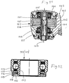
- the handpiece 102 includes a handle sleeve 103 which is bent in the usual way and of which only the foremost part can be seen.
- a hollow drive shaft 106 is freely rotatable about an axis of rotation 107 extending transversely to the grip sleeve 103 in two roller bearings 108, 109, of which the tool-side roller bearing 108 in the region of the bottom of the housing 105 and the one remote from the tool Rolling bearings 109 are arranged in the cover 104.
- a tool (not shown) with its shank can be inserted into the drive shaft 106 projecting outwardly through the hole in a hole and clamped in the inserted position by a clamping device 111.
- the clamping device 111 is formed by a plurality of spring tongues in the hollow drive shaft 106, which are bent apart when the tool shank is inserted and press radially inward against the shank.
- a turbine wheel 112 is fixedly arranged on the drive shaft 106, to which a compressed air channel (not shown) extending through the grip sleeve 103 is directed.
- the compressed air can be switched on by a switch, also not shown.
- Both roller bearings 108, 109 are each assigned a locking or sealing disk 115 which is effective between the inner ring 113 and the outer ring 114, the design and arrangement of which can be seen in FIG. 12, which enlarged one of the two identical roller bearings 108, 109 Axial section shows.
- the only difference in the roller bearings 108, 109 is that the associated sealing washer 115 is in each case arranged on the outside of the associated roller bearing, which are built in mirror images of one another.
- the sealing washer 115 is inserted with its outer edge into an enlarged bore 116 with a snug fit, whereby it rests on the inside against a shoulder 117 of the enlarged bore 116 and is axially delimited on the outside by a spring ring 118, which is inserted into an inner annular groove 119 in the enlarged bore 116 is releasably used.
- the inner edge of the sealing washer 115 surrounds the outer surface of the inner ring 113 with a small amount of movement, which forms the outside seal of the rolling bearing.
- EP 05 27 473 A1 describes an angular dental drilling handpiece in which a drive wheel arranged in the angular head of the handpiece with the associated roller bearing is arranged in a bearing sleeve which can be inserted into the handpiece from above.
- a labyrinth seal is provided on the side of the handpiece head near the tool between the bearing sleeve and a drive shaft receiving the drilling tool.
- the labyrinth seal has an axially outer labyrinth ring and an axially inner labyrinth ring, of which the outer is fixed in a rotationally fixed manner to the drive shaft and protrudes radially outward, and from which the inner labyrinth ring protrudes radially inward from the bearing sleeve and is integrally formed on the bearing sleeve, wherein the outer labyrinth ring has a coaxially inwardly projecting hollow cylindrical ring section which overlaps an outwardly projecting hollow cylindrical ring section arranged on the inner labyrinth ring.
- this labyrinth seal is surrounded by a protective sleeve inserted into the bearing sleeve, which covers the outer labyrinth ring at a radial distance and has a radial opening in the region of a radial step surface of the outer labyrinth ring, through which dirt particles should be able to be thrown radially outward.
- This known embodiment is complicated, multi-part and expensive to manufacture.
- the invention is based on the object of preventing or reducing the penetration of impurities into the housing or into the roller bearing or bearings in a medical or dental treatment instrument of the type specified at the outset.
- the locking ring lies with its surface facing the inner ring on the inner ring and is detachably or non-releasably tightly connected to the inner ring.
- the embodiment according to claim 3 leads to a simple and gentle for the rolling bearing attachment of the locking ring on the inner ring or outer ring, a stable and tight attachment is achieved without a distortion occurs on the inner and outer ring due to overheating, the operability of the rolling bearing and would affect its lifespan.
- the desired goal is achieved by a labyrinth seal which, both by itself and in combination with an embodiment according to claims 1 to 8, leads to an advantageous sealing of the interior or storage space.
- Such an S-shaped labyrinth path can be formed by two axially projecting hollow cylindrical labyrinth ring sections, of which the labyrinth ring section which is arranged on the outer labyrinth ring and which projects inwards overlaps an outwardly facing labyrinth ring section arranged on the inner labyrinth ring with a gap.
- the axially inner labyrinth ring can be permanently attached to the head housing of the handpiece, e.g. by pressing, gluing or by a one-piece design on the head housing.
- the configurations according to the invention are preferably suitable for a so-called turbine handpiece, in which the drive shaft continues to run after its drive has been switched off.
- the locking ring (s) and / or the paddle wheel (s) can be arranged on the inside and / or outside on the associated roller bearing or can be attached to the inner ring of the roller bearing.
- the paddle wheel can consist of a ring and vanes or blades projecting radially therefrom, the width of the blades preferably diverging outward, in particular only on one side of the paddle wheel.
- a second locking ring on the inside of the first locking ring or paddle wheel, which is held in particular on the opposite outer or inner ring of the associated roller bearing.
- the second locking ring can cooperate sealingly with the inner ring or the sleeve. It is also advantageous to make the arrangement such that a preferably radial sealing surface, with which the first locking ring cooperates in a sealing manner, is formed by a locking ring which delimits the second locking ring on the side facing the first locking ring.
- the invention also relates to a rolling bearing with the features according to the invention, whereby the advantages already mentioned are also achieved.
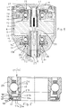
- the main parts of the angle handpiece, generally designated 1, are a grip sleeve 2, which is angled in the usual way, a so-called angle head 3 attached to its front end, a drive turbine 4 arranged therein with a turbine wheel 5, and a drive shaft 6, which is arranged in the housing 7 of the angle head 3 an axis of rotation 8 extending transversely to the grip sleeve 2 is rotatably supported by the drive turbine 4.
- a clamping sleeve 6a is fastened in the drive shaft 6, into which a treatment tool (not shown) can be inserted and clamped from the tool side of the angle head 3.
- the turbine handpiece 1 is only a part, namely the front part, of a treatment instrument with a so-called supply part (not shown), which can be detachably connected to the rear end of the turbine handpiece 1 or the grip sleeve 2, preferably by itself Known plug-in rotary coupling 9.
- supply lines Longitudinally through the grip sleeve 2, supply lines (not shown) extend like a compressed air line, which extends to the drive turbine 4, and further lines for light, air and cooling or treatment liquid or spray, which are in the front area of the Open handle sleeve 2 in the direction of the treatment site. If a plug-in / rotary coupling 9 is provided, the aforementioned lines extend through them and they are continued in the supply part and connected to a supply device, not shown.
- two roller bearings 11, 12 are provided for mounting the drive shaft 6, which are identical to one another, but are arranged in mirror image to one another.
- the tool-side roller bearing 11 is inserted in an inside bearing bore 13 in the bottom part 7a of the housing 7 and on Sealed circumference by a sealing ring 14, with its tool-side end face against an inner shoulder 13a of the bearing bore 13.
- the roller bearing 12 remote from the tool sits in a bearing bore 15 of a bearing disk 16 which is inserted into the housing 7 from the side remote from the tool and is fixed in a manner not shown.
- the roller bearing 12 remote from the tool rests with its end face remote from the tool against an inner shoulder 17 of the bearing disk 16 and is sealed therein by a sealing ring 14 which rests on its outer lateral surface.
- the housing 7 is closed on its side remote from the tool by a cover 18 which is axially displaceable in an axial guide 19 effective between it and the housing 7 and by a compression spring 20 clamped between it and the housing 7 or the bearing disk 16 in its end position remote from the tool against one Movement stop 21 is biased to the housing 7.
- the cover 18 has a pressure piece 22 on the inside, which, when the cover 18 is pressed in by a finger of the operating hand, moves inward a plunger 23 which is axially displaceably mounted in the drive shaft 6 and which does not have a solution wedge 24 arranged on its tool-side end shown tool is able to solve, which is inserted from the tool side into the clamping sleeve 6a inserted in the drive shaft 6.
- the turbine wheel 5 is arranged on the drive shaft 6 between the roller bearings 11, 12 and can be rotated in a free space 26 of the housing 7 by means of the above-described compressed air drive.
- the turbine wheel 5 is formed in one piece with the drive shaft 6. The latter extends outwards through a bore 27 tapered in relation to the bearing bore 13 in the base part 7a, whereby it projects beyond the base part 7a to the outside or can also end with the tool side of the base part 7a.
- roller bearing 11 near the tool on its side near the tool and the roller bearing 12 remote from the tool on its side remote from the tool are each sealed by an otherwise identical axial seal 28, which preferably forms a labyrinth seal.
- the seal 28 in each case comprises two disk-shaped locking rings or sealing rings 31, 32 arranged axially one behind the other, which in the present embodiment are each formed by a flat annular disk.
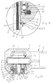
- the outer sealing ring 31 is fixed by laser spot welding 33 to the inner ring 34, preferably on the outer end face 34a of the inner ring 34 lies flat.
- the outer edge of the outer sealing ring 31 cooperates with the outer ring 37 to form a sealing joint 36, its cylindrical circumferential surface with little movement play, forming an axial sealing gap, with the cylindrical inner surface of the outer ring 37 and / or with its inner end face 39 when forming a sealing joint 41 can cooperate with an outwardly facing approximately radial sealing surface 42 of the outer ring 37.
- the radial sealing surface 42 is a shoulder surface projecting inwards from the outer ring 37, which is at a distance from the tool-side end face of the outer ring 37, so that the outer sealing ring 31 is recessed in the outer ring 37 and preferably ends on the tool side with its end face.
- the sealing ring 31 is preferably part of a labyrinth seal with the second sealing ring 32, which is preferably arranged on the inside of the sealing ring 31 and is seated in a bore extension 43, the inner circumferential groove 43 and lies on the inside against a shoulder surface 44 and is delimited on the outside by a releasable retaining ring 45 which is in a Inner groove 43a sits.
- the inner sealing ring 32 is also formed by a flat washer.
- the radial sealing surface 42 cooperating with the outer sealing ring 31 is formed by the outside of the flat locking ring 45, so that no special shoulder surface is required.
- a common, stepped inner circumferential groove is provided for receiving the inner locking ring or sealing ring 32 and the locking ring 45.
- the free inner cross-section of the inner locking ring or sealing ring 32 is adapted to the outer cross-section of the inner ring 34 so that there is a sealing joint 46 with little movement between the two approximately cylindrical sealing surfaces.
- the roller bearings 11, 12 are each formed by a ball groove bearing, the ball groove 47 in the inner ring 34 being open on the outside.
- the ball groove 47 adjoins a conical surface 48 with a slight inclination which diverges toward it and which forms the outer lateral surface of the inner ring 34 and also the sealing surface for the inner sealing ring 32.
- the inner circumferential surface of the inner locking ring or sealing ring 32 is preferably adapted to the inclination of the conical surface 48.
- the roller bearing 12 remote from the tool is arranged and designed accordingly, taking into account its mirror-image arrangement, so that a separate description is not required.
- the tool-side sealing of the roller bearing 11 can also be effected or improved in addition to the seal described above in that a slinger ring 51 or a centrifugal disc is fixedly arranged on the drive shaft 6 in front of the roller bearing 11 or behind the roller bearing 12, which preferably has a surface of the housing 7 or an add-on part of the same cooperates to form a sealing joint 52 with little movement.
- the end surface of the centrifugal ring 51 remote from the tool is a first sealing surface 53 which interacts with a second sealing surface 54 of the housing 7, which is preferably the outer surface of the housing 7 close to the tool.
- the slinger ring 51 represents a considerable hurdle because the contaminants are deflected radially and are thrown off due to the centrifugal force increase that occurs.
- Such particularly liquid substances which should adhere to the centrifugal ring 51 despite this centrifugal effect and should crawl further towards the roller bearing 11, are expected to encounter a hurdle that can hardly be overcome on the side of the centrifugal ring 51 remote from the tool, because the contaminants against the centrifugal force acting radially outward Slingshot ring 51 would have to crawl radially inwards, which is hardly possible.
- the inward creeping movement is prevented by the sealing joint 52. It is advantageous to provide the centrifugal ring 51 on its side near the tool with a circumferential groove 55 so that it has an angular cross-sectional shape. This creates another hurdle that further impedes the crawling of contaminants.
- FIGS. 4 and 5 differs from the embodiment described above in that the sealing ring 31a corresponding to the sealing ring 31 is not fastened to the inner ring 34, but is seated firmly on the drive shaft 6 , preferably on the side of the Inner ring 34 abuts. If the sealing ring 31a terminates on the tool side with the end face of the outer ring 37, the inner ring 34 is dimensioned shorter than the outer ring 37 in accordance with the axial dimension of the sealing ring 31a.
- the sealing ring 31a is preferably arranged in one piece, in particular at the tool-oriented end of a short sleeve 31b , which ensures a firm fit on the drive shaft 6 and rests with its end remote from the tool on the inner ring 34.
- the latter is to be dimensioned shorter accordingly.
- sealing ring 31a is provided with an inwardly facing, preferably hollow cylindrical sleeve 31b, it is advantageous to allow the inner sealing ring 32a to cooperate in a sealing manner with the outer circumferential surface 57 of the sleeve 31b at a sealing joint 46a with little movement play, wherein cylindrical sealing surfaces are realized here can.
- the outer sealing ring 31 is made of steel for fastening by welding, which can be welded to the inner ring 34, or it can also consist of plastic in another of the specified types of fastening.
- the inner sealing ring 32 and / or the outer sealing ring 31a with the sleeve 31b can also consist of steel or plastic.
- the ventilation device 61 can be formed by a paddle wheel 63 which is directly or indirectly connected to the drive shaft 6 or an attachment part thereof and is thus driven by the existing drive.
- the paddle wheel 63 can be arranged in the inner and / or outer and / or middle region of the housing wall 7a, where it blocks the air flow 62 by generating an overpressure in the case of an internal arrangement and / or a vacuum in the case of the outside Arrangement and / or an overpressure and underpressure generated with a medium arrangement.
- the paddle wheel 63 with respect to the roller bearing 11 , 12 is arranged on the outside and / or on the inside, it preferably being able to bear axially on the inner ring 34 of the roller bearing 11, 12.
- Another advantageous embodiment is to attach the paddle wheel 63 to the inner ring 34 so that it forms a solid structural unit with the roller bearing 11, 12 and can be prefabricated and assembled or disassembled with the latter, so that individual assembly of the paddle wheel 63 is not required.
- the paddle wheel 63 can be fastened to the inner ring 34 by being pressed on or pressed in, screwing, gluing or welding or spot welding.
- An advantageous welding or spot welding measure is laser welding, with which targeted, clean and stable welding can be carried out, with harmful distortion of the components being prevented with relatively low heating.
- a paddle wheel 63 is fastened to the inner ring 34 or 113 of a rolling bearing 11, 12 or 108, 109 of the known or the present embodiment described at the outset, in particular laser spot welded.
- the paddle wheel 63 which preferably consists of a hollow cylindrical ring 64 and radially projecting set vanes or blades 65, can, with a suitable design, be placed on the inner ring 34 or rest on the end face thereof.
- the length of the blades 65 corresponds approximately to the radial dimension of the gap a between the inner ring 34 and the outer ring 37, but the blades 65 can also be dimensioned somewhat longer so that they extend into the radial area of the outer ring 37.
- the blades 65 are arranged somewhat recessed into the gap a, a small movement gap being provided between the blades 65 and the outer ring 37, and the inner ring 34 being able to be dimensioned somewhat shorter than that Outer ring 37, preferably about the dimension of the axial width of the ring 64.
- an annular recess 66 is provided in which the impeller 63 is arranged in whole or in part. Radially outside the ring recess 66, the outer ring 37 is axially supported on an associated inner surface of the wall 7a of the housing 7 by abutment.
- the impeller 63 is arranged so far that it is sunk into the roller bearing 11, 12 a small distance between the blades 65 and the retaining ring 45 (FIGS. 3 and 5) or 119 (FIG. 11) is provided.
- the drive shaft 7 is mounted in two roller bearings 11, 12, the features described above for the arrangement of at least one paddle wheel 63 can be assigned to the roller bearing 11 close to the tool and / or the roller bearing 12 remote from the tool. 6, the paddle wheels 63 are arranged on the outside of the roller bearings 11, 12.
- the above-described ventilation device 61 is preferably suitable for a turbine handpiece in which the turbine wheel 5 continues to run after the compressed air supply has been switched off due to its inertia and thereby generates an inward suction flow which favors the entry of contaminants. Due to the outward air flow 62 according to the invention, the suction flow and the entry of impurities are effectively counteracted.
- the blades 65 are shaped radially outward divergent, so that even with a relatively narrow ring 64 a satisfactory delivery rate for the blade wheel 63 is achieved.
- the paddle wheel 63 is fixedly arranged in the front region of the housing 7 on the drive shaft 6, it being in front of the end face of the housing 7 (not shown) or can be arranged sunk into the housing 7, preferably in an annular recess 66a, which is an expansion of the annular gap S between the drive shaft 6 and the housing 7.
- the transition between the ring recesses 66, 66a and the annular gap S can be rounded or beveled, as is shown in FIG. 9.
- a labyrinth seal 71 is arranged between the wall 7a of the housing 7 on the tool side and the drive shaft 6, but also does not provide an effective barrier against solid dirt parts solid dirt such as liquids.
- the labyrinth seal 71 has two labyrinth rings 72, 73 which overlap one another axially and preferably also radially.
- the labyrinth rings 72, 73 consist of plastic or preferably Metal, especially steel.
- the axially outer labyrinth ring 72 is fixedly arranged on the drive shaft 6 with a suitable bore 72a and is fastened, for example, by pressing, gluing or welding.
- this labyrinth ring 72 is advantageous to arrange this labyrinth ring 72 on the drive shaft 6 such that its outer side surface 72a is approximately flush with the tool-side surface 7b of the housing 7.
- the bore 7c present in the housing wall 7a is larger than usual and is dimensioned here with such a radial distance from the drive shaft 6 that between the cylindrical peripheral surface 72c of the labyrinth ring 72 and the cylindrical wall of the bore 7c is a small one Gap exists.
- the axially outer labyrinth ring 72 with its outer side surface 72b, forms a centrifugal surface, on which impurities are thrown off radially when the drive shaft rotates with a tool. It is therefore also a slinger.
- the axially inner labyrinth ring 73 is non-rotatably attached to the housing wall 7a, e.g. arranged in one piece, or inserted into a corresponding receiving hole and fastened therein, e.g. by pressing, gluing or welding.
- the labyrinth ring 73 can be inserted in the bore 7c.
- a step-shaped bore extension 7d is provided, in which the labyrinth ring 73 with its outer peripheral surface is firmly inserted.
- a small radial gap S1 is also provided between the labyrinth rings 72, 73, through which the labyrinth is formed.
- the axially outer labyrinth ring 72 on its outer circumference and the axially inner labyrinth ring 73 on its inner circumference each have a sleeve-shaped, preferably hollow cylindrical axial ring shoulder 74, 75 which axially protrude and overlap, the ring shoulder 74 of the axially front labyrinth ring 72 having the ring shoulder 75 of the axially inner labyrinth ring 73 overlaps with a radial distance forming the gap S1.
- labyrinth seal 71 or another labyrinth seal is particularly suitable in combination with an axial seal or cover of the associated roller bearing 11, as shown in FIG. 10.
- FIG. 10 shows a modified configuration or arrangement of the axially inner labyrinth ring 73.
- the labyrinth ring 73 is arranged in one piece on the outer ring of the existing roller bearing 11, here by an axially and correspondingly angled extension of the outer ring.
- the labyrinth ring 73 can be prefabricated on the roller bearing 11 and assembled with it.
- the drive shaft 6 can preferably be installed and removed from the side remote from the tool, with the turbine wheel 5 and the roller bearings 11, 12.
- the locking rings 31, 31a can be made of plastic or preferably of metal or steel, with their peripheral portions sealingly contacting the associated contact part and thus being able to form a sealing washer, or they are forming locking washers whose locking peripheral portions have a small axial or radial distance (play) from them have adjacent component and thus limit a gap, whereby a cover or a labyrinth gap is created.
- sealing ring 31 or 31a each form a locking or slinger ring because they are connected directly or indirectly to the drive shaft 6 and thus participate in the rotation. It is therefore advantageous to dimension the radial dimensions of the sealing rings 31 and 31a as large as possible and to design them in the form of disks, so that a considerable centrifugal effect is achieved.
- centrifugal ring 51 then fulfills a sealing function in the sense of a sealing ring or a sealing washer if it cooperates in a sealing manner with the housing 7 or an attachment part thereof, i.e. Forms sealing surfaces.
- the sealing rings 31 thus also perform a centrifugal function.
- both the sealing rings 31, 31a, 32 and / or the or the slinger rings 51 form a labyrinth seal, which also contributes to the present problem solution.
Landscapes
- Health & Medical Sciences (AREA)
- General Engineering & Computer Science (AREA)
- Engineering & Computer Science (AREA)
- Oral & Maxillofacial Surgery (AREA)
- Epidemiology (AREA)
- Dentistry (AREA)
- Mechanical Engineering (AREA)
- Life Sciences & Earth Sciences (AREA)
- Animal Behavior & Ethology (AREA)
- General Health & Medical Sciences (AREA)
- Public Health (AREA)
- Veterinary Medicine (AREA)
- Dental Tools And Instruments Or Auxiliary Dental Instruments (AREA)
Applications Claiming Priority (2)
| Application Number | Priority Date | Filing Date | Title |
|---|---|---|---|
| DE4423222A DE4423222A1 (de) | 1994-07-01 | 1994-07-01 | Ärztliches oder zahnärztliches Behandlungsinstrument |
| DE4423222 | 1994-07-01 |
Publications (3)
| Publication Number | Publication Date |
|---|---|
| EP0689801A2 true EP0689801A2 (fr) | 1996-01-03 |
| EP0689801A3 EP0689801A3 (fr) | 1996-06-05 |
| EP0689801B1 EP0689801B1 (fr) | 1999-09-29 |
Family
ID=6522087
Family Applications (1)
| Application Number | Title | Priority Date | Filing Date |
|---|---|---|---|
| EP95110288A Expired - Lifetime EP0689801B1 (fr) | 1994-07-01 | 1995-06-30 | Instrument médical ou dentaire motorisé |
Country Status (5)
| Country | Link |
|---|---|
| US (1) | US5676542A (fr) |
| EP (1) | EP0689801B1 (fr) |
| JP (1) | JPH0866411A (fr) |
| AT (1) | ATE185059T1 (fr) |
| DE (2) | DE4423222A1 (fr) |
Cited By (8)
| Publication number | Priority date | Publication date | Assignee | Title |
|---|---|---|---|---|
| EP0724867A3 (fr) * | 1995-02-06 | 1996-08-14 | Nakanishi Inc. | Cartouche échangeable pour pièce à main dentaire |
| EP2226032A1 (fr) * | 2009-03-06 | 2010-09-08 | Nakanishi Inc. | Pièce à main dentaire de type injection centrale |
| WO2013144364A1 (fr) * | 2012-03-30 | 2013-10-03 | Sirona Dental Systems Gmbh | Pièce à main dentaire avec palier à roulement |
| DE102018200303A1 (de) | 2018-01-10 | 2019-07-11 | Minebea Mitsumi Inc. | Wälzlager, insbesondere für ein medizinisches oder kosmetisches Instrument |
| DE102019200371A1 (de) | 2018-01-15 | 2019-07-18 | Minebea Mitsumi Inc. | Wälzlager, insbesondere für ein medizinisches oder kosmetisches Instrument |
| DE102018201621A1 (de) | 2018-02-02 | 2019-08-08 | Minebea Mitsumi Inc. | Wälzlager, insbesondere für ein medizinisches oder kosmetisches Instrument |
| DE102022200272A1 (de) | 2021-01-20 | 2022-07-21 | Minebea Mitsumi Inc. | Wälzlager für ein medizinisches oder kosmetisches Instrument |
| WO2024260834A1 (fr) | 2023-06-22 | 2024-12-26 | Kavo Dental Gmbh | Pièce à main de turbine médicale |
Families Citing this family (23)
| Publication number | Priority date | Publication date | Assignee | Title |
|---|---|---|---|---|
| US6146137A (en) * | 1998-11-19 | 2000-11-14 | Vogel; William Charles | Contamination prevention device for ultra high speed dental type handpieces |
| JP3057567B1 (ja) | 1999-03-03 | 2000-06-26 | 株式会社ナカニシ | 歯科用プロフィ―ヘッド |
| DE10025416A1 (de) * | 2000-05-24 | 2001-12-06 | Sirona Dental Systems Gmbh | Zahnärztliches Handstück mit einem drehbar gelagerten Rotor |
| US20020168612A1 (en) * | 2000-09-14 | 2002-11-14 | Novak Eugene J. | Bearing for dental handpiece |
| WO2002022039A1 (fr) * | 2000-09-14 | 2002-03-21 | Dentsply International Inc. | Roulement ameliore pour piece a main dentaire |
| EP1355580A1 (fr) * | 2000-12-18 | 2003-10-29 | Dentsply International, Inc. | Composants ameliores de piece a main de dentisterie |
| JP2002238922A (ja) * | 2001-02-13 | 2002-08-27 | Nakanishi:Kk | 歯科用ハンドピース |
| DE10208692A1 (de) * | 2001-08-28 | 2003-03-20 | Kaltenbach & Voigt | Medizinisches oder dentalmedizinisches Handstück mit einem in einem Wälzlager gelagerten Drehteil |
| WO2003083266A1 (fr) * | 2002-03-28 | 2003-10-09 | Dentsply International Inc. | Technique d'equilibrage d'elements rotatifs de turbine sur un instrument dentaire |
| US7897336B2 (en) * | 2002-08-16 | 2011-03-01 | John Wayne Cancer Institute | Molecular lymphatic mapping of sentinel lymph nodes |
| US20040175065A1 (en) * | 2003-03-07 | 2004-09-09 | Minebea Co., Ltd. | Ball bearing assembly utilizing a labyrinth seal |
| US6790039B1 (en) * | 2003-06-02 | 2004-09-14 | Dental Ez, Inc. | Dental turbine support structure |
| US20040266539A1 (en) * | 2003-06-27 | 2004-12-30 | Delco Remy America, Inc., A Delaware Corporation | Laser staked two-piece drive shaft for a starter motor |
| WO2005089370A2 (fr) | 2004-03-16 | 2005-09-29 | Goodis Charles J | Limes endodontiques et dispositifs obturateurs, et leurs methodes de fabrication |
| PT2932934T (pt) | 2010-01-14 | 2020-09-03 | Bien Air Holding Sa | Dispositivo de deflexão centrífuga para peça de mão cirúrgica ou dentária que permite expelir os corpos estranhos |
| DE102011005870A1 (de) * | 2011-03-21 | 2012-09-27 | Kaltenbach & Voigt Gmbh | Medizinisches Turbinen-Handstück mit Rücksaugstopp |
| EP2773272B1 (fr) | 2011-10-31 | 2018-01-03 | Boston Scientific Scimed, Inc. | Dispositif médical rotatif |
| JP6287323B2 (ja) | 2013-09-24 | 2018-03-07 | 日本精工株式会社 | 歯科エアタービン用軸受ユニット及び歯科エアタービン |
| JP6311273B2 (ja) | 2013-11-01 | 2018-04-18 | 日本精工株式会社 | アンギュラ玉軸受及び歯科エアタービン |
| US20150132713A1 (en) * | 2013-11-08 | 2015-05-14 | Dentalez, Inc. | Dental handpiece with vortex-washer-driven particulate discharge |
| US10117724B2 (en) | 2014-12-25 | 2018-11-06 | Nsk Ltd. | Bearing unit for air turbine |
| CN105840649A (zh) * | 2016-06-03 | 2016-08-10 | 宁波和平鸽口腔医疗器材有限公司 | 一种专用于牙科手机微型高速轴承 |
| JP7053538B2 (ja) * | 2019-07-22 | 2022-04-12 | 株式会社モリタ製作所 | 歯科用ハンドピース |
Citations (1)
| Publication number | Priority date | Publication date | Assignee | Title |
|---|---|---|---|---|
| DE3719149A1 (de) | 1987-06-09 | 1988-12-22 | Kaltenbach & Voigt | Zahnaerztliche oder zahntechnische handstueckeinrichtung |
Family Cites Families (8)
| Publication number | Priority date | Publication date | Assignee | Title |
|---|---|---|---|---|
| GB2065829A (en) * | 1979-12-21 | 1981-07-01 | Skf Uk Ltd | Conveyor rollers; end cap bearing assemblies |
| CH640718A5 (de) * | 1980-05-13 | 1984-01-31 | Micro Mega Sa | Tete de contre-angle dentaire comprenant un dispositif empechant la penetration d'eau a l'interieur. |
| EP0374276B1 (fr) * | 1988-12-19 | 1995-04-19 | Matsutani Seisakusho Co. Ltd., | Fraise et pièce à main dentaire |
| JPH0628086Y2 (ja) * | 1990-08-24 | 1994-08-03 | 株式会社中西歯科器械製作所 | 歯科用ハンドピースの防塵装置 |
| JP3012279B2 (ja) * | 1990-05-01 | 2000-02-21 | 株式会社松谷製作所 | 歯科用ハンドピース |
| FR2671967A1 (fr) * | 1991-01-25 | 1992-07-31 | Bien Air | Piece a main notamment destinee a la chirurgie dentaire, tete de piece a main et appareillage dento-medical equipe d'une telle tete. |
| JPH0714397B2 (ja) * | 1991-08-12 | 1995-02-22 | 株式会社中西歯科器械製作所 | 歯科用ハンドピース |
| JPH07121261B2 (ja) * | 1993-05-20 | 1995-12-25 | 株式会社中西歯科器械製作所 | 歯科用ハンドピース |
-
1994
- 1994-07-01 DE DE4423222A patent/DE4423222A1/de not_active Ceased
-
1995
- 1995-06-23 US US08/494,080 patent/US5676542A/en not_active Expired - Lifetime
- 1995-06-30 JP JP7166632A patent/JPH0866411A/ja active Pending
- 1995-06-30 EP EP95110288A patent/EP0689801B1/fr not_active Expired - Lifetime
- 1995-06-30 AT AT95110288T patent/ATE185059T1/de active
- 1995-06-30 DE DE59506930T patent/DE59506930D1/de not_active Expired - Lifetime
Patent Citations (1)
| Publication number | Priority date | Publication date | Assignee | Title |
|---|---|---|---|---|
| DE3719149A1 (de) | 1987-06-09 | 1988-12-22 | Kaltenbach & Voigt | Zahnaerztliche oder zahntechnische handstueckeinrichtung |
Cited By (11)
| Publication number | Priority date | Publication date | Assignee | Title |
|---|---|---|---|---|
| EP0724867A3 (fr) * | 1995-02-06 | 1996-08-14 | Nakanishi Inc. | Cartouche échangeable pour pièce à main dentaire |
| EP2226032A1 (fr) * | 2009-03-06 | 2010-09-08 | Nakanishi Inc. | Pièce à main dentaire de type injection centrale |
| WO2013144364A1 (fr) * | 2012-03-30 | 2013-10-03 | Sirona Dental Systems Gmbh | Pièce à main dentaire avec palier à roulement |
| EP2830530B1 (fr) | 2012-03-30 | 2016-06-22 | Sirona Dental Systems GmbH | Pièce à main dentaire avec palier à roulement |
| DE102018200303A1 (de) | 2018-01-10 | 2019-07-11 | Minebea Mitsumi Inc. | Wälzlager, insbesondere für ein medizinisches oder kosmetisches Instrument |
| DE102019200371A1 (de) | 2018-01-15 | 2019-07-18 | Minebea Mitsumi Inc. | Wälzlager, insbesondere für ein medizinisches oder kosmetisches Instrument |
| DE102018201621A1 (de) | 2018-02-02 | 2019-08-08 | Minebea Mitsumi Inc. | Wälzlager, insbesondere für ein medizinisches oder kosmetisches Instrument |
| DE102022200272A1 (de) | 2021-01-20 | 2022-07-21 | Minebea Mitsumi Inc. | Wälzlager für ein medizinisches oder kosmetisches Instrument |
| WO2024260834A1 (fr) | 2023-06-22 | 2024-12-26 | Kavo Dental Gmbh | Pièce à main de turbine médicale |
| EP4498975A1 (fr) * | 2023-06-22 | 2025-02-05 | KaVo Dental GmbH | Pièce à main de turbine médicale |
| CN121358429A (zh) * | 2023-06-22 | 2026-01-16 | 卡沃牙科公司 | 医用涡轮手持件 |
Also Published As
| Publication number | Publication date |
|---|---|
| JPH0866411A (ja) | 1996-03-12 |
| ATE185059T1 (de) | 1999-10-15 |
| US5676542A (en) | 1997-10-14 |
| EP0689801B1 (fr) | 1999-09-29 |
| DE59506930D1 (de) | 1999-11-04 |
| EP0689801A3 (fr) | 1996-06-05 |
| DE4423222A1 (de) | 1996-01-04 |
Similar Documents
| Publication | Publication Date | Title |
|---|---|---|
| EP0689801B1 (fr) | Instrument médical ou dentaire motorisé | |
| DE10060152B4 (de) | Mit Luft betriebene Rotations- und Schneidevorrichtung zur Verwendung bei medizinischen und zahnmedizinischen Prozeduren | |
| EP0974308B1 (fr) | Pièce à main à turbine, en particulier pour des applications médicales ou dentaires | |
| EP0830848B1 (fr) | Pièce à main dentaire | |
| DE2916221C2 (de) | Schädeltrepan | |
| EP3368773B1 (fr) | Dispositif d'aspiration d'air pour une hotte aspirante | |
| DE3419964C2 (de) | Spritzkopf eines Hochdruckreinigungsgerätes | |
| DE2059008A1 (de) | Drosselklappe fuer eine Rohrleitung | |
| EP1420712B1 (fr) | Piece a main medicale ou dentaire comprenant une partie rotative logee dans un palier a roulement | |
| DE1628648A1 (de) | Kombinierte Bodenbehandlungs- und Fluessigkeitsaufnahmevorrichtung | |
| EP1420711B1 (fr) | Piece a main utilisee en medecine ou en medecine dentaire et comprenant au moins une partie rotative | |
| DE8707880U1 (de) | Lager mit Dichtung | |
| DE2947340A1 (de) | Kreiselegge | |
| EP1716817B1 (fr) | Pièce à main médicale, en particulier dentaire | |
| EP0173898A1 (fr) | Dispositif de protection pour arbre de transmission | |
| DE3126177C2 (fr) | ||
| EP0670148A1 (fr) | Pièce à main motorisée, en particulier pour des fins médicales, de préférence pour un laboratoire médical ou dentaire | |
| DE2703646C2 (de) | Mit Luftturbinenantrieb versehenes zahnärztliches Handstück | |
| DE10130898C2 (de) | Handstück für ein medizinisches oder kosmetisches Bearbeitungsgerät | |
| DE10130897C1 (de) | Handstück für ein Medizinisches oder kosmetisches Bearbeitungsgerät | |
| EP0433647A1 (fr) | Faucheuse rotative | |
| EP0896811B1 (fr) | Instrument de traitement médical ou dentaire | |
| DE9319555U1 (de) | Rotationszerstäuber mit einem Glockenkörper | |
| DE20022295U1 (de) | Vorrichtung mit einem Gasförderelement | |
| DE9320012U1 (de) | Lagerung für Dispergierschäfte |
Legal Events
| Date | Code | Title | Description |
|---|---|---|---|
| PUAI | Public reference made under article 153(3) epc to a published international application that has entered the european phase |
Free format text: ORIGINAL CODE: 0009012 |
|
| AK | Designated contracting states |
Kind code of ref document: A2 Designated state(s): AT CH DE LI |
|
| PUAL | Search report despatched |
Free format text: ORIGINAL CODE: 0009013 |
|
| AK | Designated contracting states |
Kind code of ref document: A3 Designated state(s): AT CH DE LI |
|
| 17P | Request for examination filed |
Effective date: 19961205 |
|
| GRAG | Despatch of communication of intention to grant |
Free format text: ORIGINAL CODE: EPIDOS AGRA |
|
| 17Q | First examination report despatched |
Effective date: 19981119 |
|
| GRAG | Despatch of communication of intention to grant |
Free format text: ORIGINAL CODE: EPIDOS AGRA |
|
| GRAH | Despatch of communication of intention to grant a patent |
Free format text: ORIGINAL CODE: EPIDOS IGRA |
|
| GRAH | Despatch of communication of intention to grant a patent |
Free format text: ORIGINAL CODE: EPIDOS IGRA |
|
| GRAA | (expected) grant |
Free format text: ORIGINAL CODE: 0009210 |
|
| AK | Designated contracting states |
Kind code of ref document: B1 Designated state(s): AT CH DE LI |
|
| REF | Corresponds to: |
Ref document number: 185059 Country of ref document: AT Date of ref document: 19991015 Kind code of ref document: T |
|
| REG | Reference to a national code |
Ref country code: CH Ref legal event code: NV Representative=s name: A. BRAUN, BRAUN, HERITIER, ESCHMANN AG PATENTANWAE Ref country code: CH Ref legal event code: EP |
|
| REF | Corresponds to: |
Ref document number: 59506930 Country of ref document: DE Date of ref document: 19991104 |
|
| PLBE | No opposition filed within time limit |
Free format text: ORIGINAL CODE: 0009261 |
|
| STAA | Information on the status of an ep patent application or granted ep patent |
Free format text: STATUS: NO OPPOSITION FILED WITHIN TIME LIMIT |
|
| 26N | No opposition filed | ||
| REG | Reference to a national code |
Ref country code: CH Ref legal event code: PFA Owner name: KALTENBACH & VOIGT GMBH & CO. Free format text: KALTENBACH & VOIGT GMBH & CO.#BISMARCKRING 39#88400 BIBERACH/RISS (DE) -TRANSFER TO- KALTENBACH & VOIGT GMBH & CO.#BISMARCKRING 39#88400 BIBERACH/RISS (DE) |
|
| PGFP | Annual fee paid to national office [announced via postgrant information from national office to epo] |
Ref country code: CH Payment date: 20110627 Year of fee payment: 17 |
|
| PGFP | Annual fee paid to national office [announced via postgrant information from national office to epo] |
Ref country code: AT Payment date: 20110620 Year of fee payment: 17 |
|
| PGFP | Annual fee paid to national office [announced via postgrant information from national office to epo] |
Ref country code: DE Payment date: 20110704 Year of fee payment: 17 |
|
| REG | Reference to a national code |
Ref country code: CH Ref legal event code: PL |
|
| REG | Reference to a national code |
Ref country code: CH Ref legal event code: PL Ref country code: AT Ref legal event code: MM01 Ref document number: 185059 Country of ref document: AT Kind code of ref document: T Effective date: 20120630 |
|
| REG | Reference to a national code |
Ref country code: DE Ref legal event code: R119 Ref document number: 59506930 Country of ref document: DE Effective date: 20130101 |
|
| PG25 | Lapsed in a contracting state [announced via postgrant information from national office to epo] |
Ref country code: DE Free format text: LAPSE BECAUSE OF NON-PAYMENT OF DUE FEES Effective date: 20130101 Ref country code: LI Free format text: LAPSE BECAUSE OF NON-PAYMENT OF DUE FEES Effective date: 20120630 Ref country code: CH Free format text: LAPSE BECAUSE OF NON-PAYMENT OF DUE FEES Effective date: 20120630 |
|
| PG25 | Lapsed in a contracting state [announced via postgrant information from national office to epo] |
Ref country code: AT Free format text: LAPSE BECAUSE OF NON-PAYMENT OF DUE FEES Effective date: 20120630 |