EP0689868A1 - Réacteur pour la réalisation de réactions corrosives sans haute température et haute pression - Google Patents
Réacteur pour la réalisation de réactions corrosives sans haute température et haute pression Download PDFInfo
- Publication number
- EP0689868A1 EP0689868A1 EP95109643A EP95109643A EP0689868A1 EP 0689868 A1 EP0689868 A1 EP 0689868A1 EP 95109643 A EP95109643 A EP 95109643A EP 95109643 A EP95109643 A EP 95109643A EP 0689868 A1 EP0689868 A1 EP 0689868A1
- Authority
- EP
- European Patent Office
- Prior art keywords
- reactor
- vessel
- pressure
- containment vessel
- outer containment
- Prior art date
- Legal status (The legal status is an assumption and is not a legal conclusion. Google has not performed a legal analysis and makes no representation as to the accuracy of the status listed.)
- Withdrawn
Links
- 231100000069 corrosive reaction Toxicity 0.000 title abstract description 10
- 238000006243 chemical reaction Methods 0.000 claims abstract description 63
- 239000000463 material Substances 0.000 claims abstract description 29
- 229910045601 alloy Inorganic materials 0.000 claims abstract description 5
- 239000000956 alloy Substances 0.000 claims abstract description 5
- 239000012530 fluid Substances 0.000 claims description 33
- CURLTUGMZLYLDI-UHFFFAOYSA-N Carbon dioxide Chemical compound O=C=O CURLTUGMZLYLDI-UHFFFAOYSA-N 0.000 claims description 14
- 238000005260 corrosion Methods 0.000 claims description 14
- 230000007797 corrosion Effects 0.000 claims description 14
- 239000000203 mixture Substances 0.000 claims description 14
- 239000000919 ceramic Substances 0.000 claims description 11
- IJGRMHOSHXDMSA-UHFFFAOYSA-N Atomic nitrogen Chemical compound N#N IJGRMHOSHXDMSA-UHFFFAOYSA-N 0.000 claims description 10
- VYPSYNLAJGMNEJ-UHFFFAOYSA-N Silicium dioxide Chemical compound O=[Si]=O VYPSYNLAJGMNEJ-UHFFFAOYSA-N 0.000 claims description 10
- 229910001092 metal group alloy Inorganic materials 0.000 claims description 10
- 239000011521 glass Substances 0.000 claims description 8
- 238000012546 transfer Methods 0.000 claims description 8
- 229910000975 Carbon steel Inorganic materials 0.000 claims description 7
- 229910002092 carbon dioxide Inorganic materials 0.000 claims description 7
- 239000011810 insulating material Substances 0.000 claims description 7
- RTAQQCXQSZGOHL-UHFFFAOYSA-N Titanium Chemical compound [Ti] RTAQQCXQSZGOHL-UHFFFAOYSA-N 0.000 claims description 6
- 239000010936 titanium Substances 0.000 claims description 6
- 229910052719 titanium Inorganic materials 0.000 claims description 6
- 239000001569 carbon dioxide Substances 0.000 claims description 5
- 229910052681 coesite Inorganic materials 0.000 claims description 5
- 238000001816 cooling Methods 0.000 claims description 5
- 229910052906 cristobalite Inorganic materials 0.000 claims description 5
- 239000000377 silicon dioxide Substances 0.000 claims description 5
- 235000012239 silicon dioxide Nutrition 0.000 claims description 5
- 229910052682 stishovite Inorganic materials 0.000 claims description 5
- 229910052905 tridymite Inorganic materials 0.000 claims description 5
- 239000003570 air Substances 0.000 claims description 4
- 239000002131 composite material Substances 0.000 claims description 4
- 239000001307 helium Substances 0.000 claims description 4
- 229910052734 helium Inorganic materials 0.000 claims description 4
- SWQJXJOGLNCZEY-UHFFFAOYSA-N helium atom Chemical compound [He] SWQJXJOGLNCZEY-UHFFFAOYSA-N 0.000 claims description 4
- 229910052757 nitrogen Inorganic materials 0.000 claims description 4
- 229920000642 polymer Polymers 0.000 claims description 4
- 229910000601 superalloy Inorganic materials 0.000 claims description 4
- VYZAMTAEIAYCRO-UHFFFAOYSA-N Chromium Chemical compound [Cr] VYZAMTAEIAYCRO-UHFFFAOYSA-N 0.000 claims description 3
- 230000008878 coupling Effects 0.000 claims description 3
- 238000010168 coupling process Methods 0.000 claims description 3
- 238000005859 coupling reaction Methods 0.000 claims description 3
- 238000009413 insulation Methods 0.000 claims description 3
- TWNQGVIAIRXVLR-UHFFFAOYSA-N oxo(oxoalumanyloxy)alumane Chemical compound O=[Al]O[Al]=O TWNQGVIAIRXVLR-UHFFFAOYSA-N 0.000 claims description 3
- 239000000126 substance Substances 0.000 claims description 3
- 229910019589 Cr—Fe Inorganic materials 0.000 claims description 2
- -1 InconelTM X) Inorganic materials 0.000 claims description 2
- XAGFODPZIPBFFR-UHFFFAOYSA-N aluminium Chemical compound [Al] XAGFODPZIPBFFR-UHFFFAOYSA-N 0.000 claims description 2
- 229920001296 polysiloxane Polymers 0.000 claims description 2
- 238000011144 upstream manufacturing Methods 0.000 claims 2
- XLYOFNOQVPJJNP-UHFFFAOYSA-N water Substances O XLYOFNOQVPJJNP-UHFFFAOYSA-N 0.000 abstract description 19
- 238000010276 construction Methods 0.000 abstract description 6
- 229910052751 metal Inorganic materials 0.000 abstract description 5
- 239000002184 metal Substances 0.000 abstract description 5
- 150000002739 metals Chemical class 0.000 abstract description 3
- 230000000630 rising effect Effects 0.000 abstract 1
- 238000009284 supercritical water oxidation Methods 0.000 description 15
- 239000000047 product Substances 0.000 description 8
- 238000010438 heat treatment Methods 0.000 description 7
- 238000000034 method Methods 0.000 description 6
- 239000000376 reactant Substances 0.000 description 6
- 239000010962 carbon steel Substances 0.000 description 5
- 239000010802 sludge Substances 0.000 description 5
- 239000013529 heat transfer fluid Substances 0.000 description 4
- MHAJPDPJQMAIIY-UHFFFAOYSA-N Hydrogen peroxide Chemical compound OO MHAJPDPJQMAIIY-UHFFFAOYSA-N 0.000 description 3
- 238000013461 design Methods 0.000 description 3
- 238000000605 extraction Methods 0.000 description 3
- 239000007800 oxidant agent Substances 0.000 description 3
- 230000001590 oxidative effect Effects 0.000 description 3
- 230000009467 reduction Effects 0.000 description 3
- 239000000243 solution Substances 0.000 description 3
- XEEYBQQBJWHFJM-UHFFFAOYSA-N Iron Chemical compound [Fe] XEEYBQQBJWHFJM-UHFFFAOYSA-N 0.000 description 2
- PXHVJJICTQNCMI-UHFFFAOYSA-N Nickel Chemical compound [Ni] PXHVJJICTQNCMI-UHFFFAOYSA-N 0.000 description 2
- 229940024548 aluminum oxide Drugs 0.000 description 2
- 230000008901 benefit Effects 0.000 description 2
- 229910001873 dinitrogen Inorganic materials 0.000 description 2
- 239000011491 glass wool Substances 0.000 description 2
- 239000007788 liquid Substances 0.000 description 2
- 230000007246 mechanism Effects 0.000 description 2
- 238000012986 modification Methods 0.000 description 2
- 230000004048 modification Effects 0.000 description 2
- 230000008569 process Effects 0.000 description 2
- OKTJSMMVPCPJKN-UHFFFAOYSA-N Carbon Chemical compound [C] OKTJSMMVPCPJKN-UHFFFAOYSA-N 0.000 description 1
- MYMOFIZGZYHOMD-UHFFFAOYSA-N Dioxygen Chemical compound O=O MYMOFIZGZYHOMD-UHFFFAOYSA-N 0.000 description 1
- QCWXUUIWCKQGHC-UHFFFAOYSA-N Zirconium Chemical compound [Zr] QCWXUUIWCKQGHC-UHFFFAOYSA-N 0.000 description 1
- QVGXLLKOCUKJST-UHFFFAOYSA-N atomic oxygen Chemical compound [O] QVGXLLKOCUKJST-UHFFFAOYSA-N 0.000 description 1
- 229910052799 carbon Inorganic materials 0.000 description 1
- 239000003054 catalyst Substances 0.000 description 1
- 230000003197 catalytic effect Effects 0.000 description 1
- 238000005524 ceramic coating Methods 0.000 description 1
- 230000008859 change Effects 0.000 description 1
- 238000003889 chemical engineering Methods 0.000 description 1
- 239000007795 chemical reaction product Substances 0.000 description 1
- 229910052804 chromium Inorganic materials 0.000 description 1
- 239000011651 chromium Substances 0.000 description 1
- BIJOYKCOMBZXAE-UHFFFAOYSA-N chromium iron nickel Chemical compound [Cr].[Fe].[Ni] BIJOYKCOMBZXAE-UHFFFAOYSA-N 0.000 description 1
- 239000004927 clay Substances 0.000 description 1
- 239000000498 cooling water Substances 0.000 description 1
- 238000005336 cracking Methods 0.000 description 1
- 238000006731 degradation reaction Methods 0.000 description 1
- 229910001882 dioxygen Inorganic materials 0.000 description 1
- 239000007789 gas Substances 0.000 description 1
- 238000010348 incorporation Methods 0.000 description 1
- 239000011261 inert gas Substances 0.000 description 1
- 238000002347 injection Methods 0.000 description 1
- 239000007924 injection Substances 0.000 description 1
- 239000000543 intermediate Substances 0.000 description 1
- 229910052742 iron Inorganic materials 0.000 description 1
- VUZPPFZMUPKLLV-UHFFFAOYSA-N methane;hydrate Chemical compound C.O VUZPPFZMUPKLLV-UHFFFAOYSA-N 0.000 description 1
- 238000002156 mixing Methods 0.000 description 1
- 239000002991 molded plastic Substances 0.000 description 1
- 229910052759 nickel Inorganic materials 0.000 description 1
- 239000003960 organic solvent Substances 0.000 description 1
- 239000010815 organic waste Substances 0.000 description 1
- 238000007254 oxidation reaction Methods 0.000 description 1
- 239000000075 oxide glass Substances 0.000 description 1
- 239000012476 oxidizable substance Substances 0.000 description 1
- 239000001301 oxygen Substances 0.000 description 1
- 229910052760 oxygen Inorganic materials 0.000 description 1
- 230000037361 pathway Effects 0.000 description 1
- 239000002244 precipitate Substances 0.000 description 1
- 238000010926 purge Methods 0.000 description 1
- 230000001105 regulatory effect Effects 0.000 description 1
- 150000003839 salts Chemical class 0.000 description 1
- 238000000926 separation method Methods 0.000 description 1
- 239000002002 slurry Substances 0.000 description 1
- 238000000194 supercritical-fluid extraction Methods 0.000 description 1
- 239000002699 waste material Substances 0.000 description 1
- 238000009279 wet oxidation reaction Methods 0.000 description 1
- 229910052726 zirconium Inorganic materials 0.000 description 1
Images


Classifications
-
- B—PERFORMING OPERATIONS; TRANSPORTING
- B01—PHYSICAL OR CHEMICAL PROCESSES OR APPARATUS IN GENERAL
- B01J—CHEMICAL OR PHYSICAL PROCESSES, e.g. CATALYSIS OR COLLOID CHEMISTRY; THEIR RELEVANT APPARATUS
- B01J19/00—Chemical, physical or physico-chemical processes in general; Their relevant apparatus
- B01J19/24—Stationary reactors without moving elements inside
- B01J19/2415—Tubular reactors
- B01J19/243—Tubular reactors spirally, concentrically or zigzag wound
-
- B—PERFORMING OPERATIONS; TRANSPORTING
- B01—PHYSICAL OR CHEMICAL PROCESSES OR APPARATUS IN GENERAL
- B01J—CHEMICAL OR PHYSICAL PROCESSES, e.g. CATALYSIS OR COLLOID CHEMISTRY; THEIR RELEVANT APPARATUS
- B01J19/00—Chemical, physical or physico-chemical processes in general; Their relevant apparatus
- B01J19/0006—Controlling or regulating processes
-
- B—PERFORMING OPERATIONS; TRANSPORTING
- B01—PHYSICAL OR CHEMICAL PROCESSES OR APPARATUS IN GENERAL
- B01J—CHEMICAL OR PHYSICAL PROCESSES, e.g. CATALYSIS OR COLLOID CHEMISTRY; THEIR RELEVANT APPARATUS
- B01J19/00—Chemical, physical or physico-chemical processes in general; Their relevant apparatus
- B01J19/0006—Controlling or regulating processes
- B01J19/0013—Controlling the temperature of the process
-
- B—PERFORMING OPERATIONS; TRANSPORTING
- B01—PHYSICAL OR CHEMICAL PROCESSES OR APPARATUS IN GENERAL
- B01J—CHEMICAL OR PHYSICAL PROCESSES, e.g. CATALYSIS OR COLLOID CHEMISTRY; THEIR RELEVANT APPARATUS
- B01J19/00—Chemical, physical or physico-chemical processes in general; Their relevant apparatus
- B01J19/0053—Details of the reactor
- B01J19/0066—Stirrers
-
- B—PERFORMING OPERATIONS; TRANSPORTING
- B01—PHYSICAL OR CHEMICAL PROCESSES OR APPARATUS IN GENERAL
- B01J—CHEMICAL OR PHYSICAL PROCESSES, e.g. CATALYSIS OR COLLOID CHEMISTRY; THEIR RELEVANT APPARATUS
- B01J19/00—Chemical, physical or physico-chemical processes in general; Their relevant apparatus
- B01J19/02—Apparatus characterised by being constructed of material selected for its chemically-resistant properties
-
- B—PERFORMING OPERATIONS; TRANSPORTING
- B01—PHYSICAL OR CHEMICAL PROCESSES OR APPARATUS IN GENERAL
- B01J—CHEMICAL OR PHYSICAL PROCESSES, e.g. CATALYSIS OR COLLOID CHEMISTRY; THEIR RELEVANT APPARATUS
- B01J19/00—Chemical, physical or physico-chemical processes in general; Their relevant apparatus
- B01J19/24—Stationary reactors without moving elements inside
- B01J19/2415—Tubular reactors
- B01J19/242—Tubular reactors in series
-
- B—PERFORMING OPERATIONS; TRANSPORTING
- B01—PHYSICAL OR CHEMICAL PROCESSES OR APPARATUS IN GENERAL
- B01J—CHEMICAL OR PHYSICAL PROCESSES, e.g. CATALYSIS OR COLLOID CHEMISTRY; THEIR RELEVANT APPARATUS
- B01J3/00—Processes of utilising sub-atmospheric or super-atmospheric pressure to effect chemical or physical change of matter; Apparatus therefor
- B01J3/008—Processes carried out under supercritical conditions
-
- B—PERFORMING OPERATIONS; TRANSPORTING
- B01—PHYSICAL OR CHEMICAL PROCESSES OR APPARATUS IN GENERAL
- B01J—CHEMICAL OR PHYSICAL PROCESSES, e.g. CATALYSIS OR COLLOID CHEMISTRY; THEIR RELEVANT APPARATUS
- B01J3/00—Processes of utilising sub-atmospheric or super-atmospheric pressure to effect chemical or physical change of matter; Apparatus therefor
- B01J3/04—Pressure vessels, e.g. autoclaves
-
- B—PERFORMING OPERATIONS; TRANSPORTING
- B01—PHYSICAL OR CHEMICAL PROCESSES OR APPARATUS IN GENERAL
- B01J—CHEMICAL OR PHYSICAL PROCESSES, e.g. CATALYSIS OR COLLOID CHEMISTRY; THEIR RELEVANT APPARATUS
- B01J3/00—Processes of utilising sub-atmospheric or super-atmospheric pressure to effect chemical or physical change of matter; Apparatus therefor
- B01J3/04—Pressure vessels, e.g. autoclaves
- B01J3/046—Pressure-balanced vessels
-
- C—CHEMISTRY; METALLURGY
- C02—TREATMENT OF WATER, WASTE WATER, SEWAGE, OR SLUDGE
- C02F—TREATMENT OF WATER, WASTE WATER, SEWAGE, OR SLUDGE
- C02F11/00—Treatment of sludge; Devices therefor
- C02F11/06—Treatment of sludge; Devices therefor by oxidation
- C02F11/08—Wet air oxidation
- C02F11/086—Wet air oxidation in the supercritical state
-
- B—PERFORMING OPERATIONS; TRANSPORTING
- B01—PHYSICAL OR CHEMICAL PROCESSES OR APPARATUS IN GENERAL
- B01J—CHEMICAL OR PHYSICAL PROCESSES, e.g. CATALYSIS OR COLLOID CHEMISTRY; THEIR RELEVANT APPARATUS
- B01J2219/00—Chemical, physical or physico-chemical processes in general; Their relevant apparatus
- B01J2219/00049—Controlling or regulating processes
- B01J2219/00051—Controlling the temperature
- B01J2219/00074—Controlling the temperature by indirect heating or cooling employing heat exchange fluids
- B01J2219/00087—Controlling the temperature by indirect heating or cooling employing heat exchange fluids with heat exchange elements outside the reactor
-
- B—PERFORMING OPERATIONS; TRANSPORTING
- B01—PHYSICAL OR CHEMICAL PROCESSES OR APPARATUS IN GENERAL
- B01J—CHEMICAL OR PHYSICAL PROCESSES, e.g. CATALYSIS OR COLLOID CHEMISTRY; THEIR RELEVANT APPARATUS
- B01J2219/00—Chemical, physical or physico-chemical processes in general; Their relevant apparatus
- B01J2219/00049—Controlling or regulating processes
- B01J2219/00162—Controlling or regulating processes controlling the pressure
-
- B—PERFORMING OPERATIONS; TRANSPORTING
- B01—PHYSICAL OR CHEMICAL PROCESSES OR APPARATUS IN GENERAL
- B01J—CHEMICAL OR PHYSICAL PROCESSES, e.g. CATALYSIS OR COLLOID CHEMISTRY; THEIR RELEVANT APPARATUS
- B01J2219/00—Chemical, physical or physico-chemical processes in general; Their relevant apparatus
- B01J2219/02—Apparatus characterised by their chemically-resistant properties
- B01J2219/0204—Apparatus characterised by their chemically-resistant properties comprising coatings on the surfaces in direct contact with the reactive components
- B01J2219/0209—Apparatus characterised by their chemically-resistant properties comprising coatings on the surfaces in direct contact with the reactive components of glass
-
- B—PERFORMING OPERATIONS; TRANSPORTING
- B01—PHYSICAL OR CHEMICAL PROCESSES OR APPARATUS IN GENERAL
- B01J—CHEMICAL OR PHYSICAL PROCESSES, e.g. CATALYSIS OR COLLOID CHEMISTRY; THEIR RELEVANT APPARATUS
- B01J2219/00—Chemical, physical or physico-chemical processes in general; Their relevant apparatus
- B01J2219/02—Apparatus characterised by their chemically-resistant properties
- B01J2219/0204—Apparatus characterised by their chemically-resistant properties comprising coatings on the surfaces in direct contact with the reactive components
- B01J2219/0218—Apparatus characterised by their chemically-resistant properties comprising coatings on the surfaces in direct contact with the reactive components of ceramic
-
- B—PERFORMING OPERATIONS; TRANSPORTING
- B01—PHYSICAL OR CHEMICAL PROCESSES OR APPARATUS IN GENERAL
- B01J—CHEMICAL OR PHYSICAL PROCESSES, e.g. CATALYSIS OR COLLOID CHEMISTRY; THEIR RELEVANT APPARATUS
- B01J2219/00—Chemical, physical or physico-chemical processes in general; Their relevant apparatus
- B01J2219/02—Apparatus characterised by their chemically-resistant properties
- B01J2219/025—Apparatus characterised by their chemically-resistant properties characterised by the construction materials of the reactor vessel proper
- B01J2219/0277—Metal based
-
- Y—GENERAL TAGGING OF NEW TECHNOLOGICAL DEVELOPMENTS; GENERAL TAGGING OF CROSS-SECTIONAL TECHNOLOGIES SPANNING OVER SEVERAL SECTIONS OF THE IPC; TECHNICAL SUBJECTS COVERED BY FORMER USPC CROSS-REFERENCE ART COLLECTIONS [XRACs] AND DIGESTS
- Y02—TECHNOLOGIES OR APPLICATIONS FOR MITIGATION OR ADAPTATION AGAINST CLIMATE CHANGE
- Y02P—CLIMATE CHANGE MITIGATION TECHNOLOGIES IN THE PRODUCTION OR PROCESSING OF GOODS
- Y02P20/00—Technologies relating to chemical industry
- Y02P20/50—Improvements relating to the production of bulk chemicals
- Y02P20/54—Improvements relating to the production of bulk chemicals using solvents, e.g. supercritical solvents or ionic liquids
-
- Y—GENERAL TAGGING OF NEW TECHNOLOGICAL DEVELOPMENTS; GENERAL TAGGING OF CROSS-SECTIONAL TECHNOLOGIES SPANNING OVER SEVERAL SECTIONS OF THE IPC; TECHNICAL SUBJECTS COVERED BY FORMER USPC CROSS-REFERENCE ART COLLECTIONS [XRACs] AND DIGESTS
- Y10—TECHNICAL SUBJECTS COVERED BY FORMER USPC
- Y10S—TECHNICAL SUBJECTS COVERED BY FORMER USPC CROSS-REFERENCE ART COLLECTIONS [XRACs] AND DIGESTS
- Y10S588/00—Hazardous or toxic waste destruction or containment
- Y10S588/90—Apparatus
Definitions
- the present invention relates to the containment of high temperature, elevated pressure, corrosive reactions, such as supercritical water reactions and supercritical water oxidation reactions.
- supercritical water reaction refers to the broad class of chemical reactions occurring in a mixture containing a substantial portion of water at conditions near or above the critical point of pure water (the critical point of pure water is at 374.2°C and 217.6 atm). Such reactions are unique in that the properties of water at these elevated temperatures and pressures are much different than at ambient conditions.
- Supercritical and near-supercritical water possess unique solution, catalytic and dielectric properties and can be highly corrosive. Salts tend to precipitate out of solution, while the water itself tends to act like a strong organic solvent as well as a catalyst for many organic degradation reactions.
- Supercritical water oxidation reaction refers to a supercritical water reaction in which oxidant (e.g., H2O2, O2, air) is added which reacts with an oxidizable substance (e.g., an organic) contained in the feed mixture.
- oxidant e.g., H2O2, O2, air
- an oxidizable substance e.g., an organic
- Metal alloys tend to embrittle (de-anneal), as well as experience creep, when exposed to high temperatures such as those encountered in supercritical water oxidation reactions. This is especially the case for corrosion-resistant metal alloys such as nickel/chromium/iron blends, which embrittle near 500°C. This fact, coupled with the likelihood of corrosion-induced pitting or crazing on the surface of the metal alloy due to the corrosive nature of some supercritical water oxidation reactions, demands that an alternative material be used to contain the high pressure of the supercritical water oxidation reaction.
- Certain ceramics and glasses are very resistant to corrosion, but do not possess the mechanical strength to contain the high pressures typical of supercritical water oxidation reactions.
- Some exotic metals and metal alloys are also corrosion-resistant, but may embrittle and/or creep at high temperatures under strain, or be cost-prohibitive to use on a commercial basis.
- the extraction vessel would not effectively contain a high pressure, high temperature, corrosive reaction since, even if the cartridge was made of a corrosion-resistant, temperature resistant material, which is not taught, the same high temperature would be experienced by the entire apparatus, both inside and outside walls. Since the outside walls would be metal, embrittlement, loss of ductility and/or creep would eventually lead to failure of the pressure-containment vessel.
- Battelle Pacific Northwest Laboratories has disclosed a reactor which "uses a thin insert of a corrosion-resistant metal, such as titanium or zirconium, that fits close to the wall of a carbon-steel pressure vessel".
- the space between the two is filled with a commercial high-temperature heat transfer fluid.
- the insert is designed so that it can expand toward the pressure vessel outer wall when pressurized.
- the heat transfer fluid balances the pressure (as described in Chemical Engineering Magazine , December, 1992, page 17).
- This concept is similar to Allington et. al. in that an outer vessel contains the high pressure while the inner vessel does not experience a large pressure drop across its walls.
- Battelle's publication addresses the failure of the pressure-containing vessel when exposed to extended high temperatures such as those of supercritical water reactions. Rather, Battelle's publication teaches transfer of heat from the inner to the outer vessel using a heat-transfer fluid.
- This type of reactor has the following disadvantages: when the outer carbon-steel vessel is exposed to high temperatures, e.g., in the range of about 400-700°C, it will lose its ductility and may no longer be able to safely provide sufficient strength to contain the pressure. Its effective life is shortened by being brought to high temperatures.
- Swift et. al. in US Patent 4,670,404 teaches of using a thin-walled cylindrical batch reactor which is thermally insulated from the walls of a surrounding containment unit, as a pilot apparatus to design full-scale processes and emergency pressure-relief systems.
- Swift et. al. do not address or solve the problem of a potentially corrosive reaction, nor do they address the material concerns associated with an extended high-pressure, high temperature reaction. Rather, their focus is solely to design an emergency relief system which will operate regardless of whether a liquid or gas is discharged from the reactor containing a runaway exothermic reaction. No specific mention is made of containing a high pressure, high temperature, corrosive reaction.
- Binning et. al. in US Patents 4,721,575 and 4,869,833, teach a tubular plug-flow wet-oxidation reactor in which walls are exposed to potentially large pressure drops, while being immersed in a liquid heat-transfer fluid contained in a containment vessel. No solutions were disclosed for containing a high pressure, high temperature, corrosive fluid within the reactor for an extended period. Rather, Binning et. al. focused on improved mixing inside the reactor due to its curved shape.
- Huang et. al. teaches a supercritical water oxidation reactor which serves to remove precipitates from the reaction zone as they are formed, but Huang has in no way addressed the issue of high temperature, high pressure, corrosive conditions as in a supercritical water environment.
- Titmas et. al. teaches an underground deep-well injection reactor but Titmas et. al. have in no way addressed the issue of high temperature, high pressure, corrosive conditions as in a supercritical water environment.
- the reactor of this invention withstands both the operating conditions and corrosive nature of such reactions in a way that is efficient and adaptable to commercial operations.
- the invention provides an apparatus for containing a high pressure, high temperature, corrosive reaction by: (1) providing an "inner reaction vessel", having an inlet port and an outlet port, which contains, for example, the supercritical water or supercritical water oxidation reactants, intermediates, and products, and is made of a material which is resistant to corrosion and can withstand high temperature, e.g.
- a super alloy lined with a chemical resistant material (2) providing an "outer containment vessel", having an inlet port and an outlet port, which contains the high pressure at a temperature substantially lower than the "inner reactor", and is made of a material which is able to effectively contain high pressure, e.g., carbon steel, (3) providing a means for coupling the outer containment vessel inlet and outlet ports to the inner reaction vessel's inlet and outlet port, and (4) also, providing a means for coupling the outer containment vessel inlet and outlet ports to a fluid feed port and a fluid exit port, so that when the outer containment vessel is coupled to both the fluid feed and exit ports, as well as the inlet and outlet ports of the inner reaction vessel, the content of the inner reaction vessel is sealed off from the outer containment vessel.
- this invention may include means for insulating the outer containment vessel from the high temperatures of the inner reaction vessel by means of insulating materials located between the inner and outer vessels, and/or by an insulating fluid added between the inner and outer vessels, with means to cool the insulating fluid as needed to keep it below a specified maximum temperature.
- the insulating materials can be any high temperature-resistant commercial insulating product, such as glass wool.
- the insulating fluid can be helium or any other inert gas, nitrogen, carbon dioxide, air and the like, or mixtures thereof.
- the insulating fluid is kept below a preset maximum temperature in order to prolong the life of the outer reaction vessel materials of construction. This may be further accomplished by routing the insulating fluid through a water-cooled heat exchanger (designed to compensate for the high-pressure of the insulating fluid).
- the inner reactor vessel materials of construction are resistant to high temperatures and to corrosive conditions, and include the broad range of high temperature-fired ceramics, glasses, corrosion-resistant metals such as titanium, corrosion-resistant metal alloys such as nickel-chromium-iron blends, and temperature and corrosion resistant composites and polymers. More specific examples include any super alloy (Ni-Cr-Fe based alloy, e.g. InconelTM X) lined with a chemical resistant layer such as SiO2 ceramic, SiO2 glass, aluminum metal, chromium metal, boride, carbide, blown glass (100% SiO2), titanium-based alloy, silicone carbide high temperature fired ceramic, and aluminum oxide high temperature fired ceramic.
- the outer containment vessel materials of construction which serve to contain the pressure around the inner reaction vessel, include carbon steels, metal alloys and stress/strain-resistant polymers.
- the inner reaction vessel is, for example, a plug-flow type reactor, a continuous stirred-tank reactor, or a combination of several reactor types. Any appropriate means of heat exchange may be incorporated to transfer the heat of reaction to preheat the feed.
- a tubular coiled plug-flow reactor provides the additional advantage of absorbing the strain caused by temperature changes during start-up, operation and shut-down.
- Pumps for the feed streams may be piston-type or centrifugal-type pumps.
- the pressure between the inner and outer vessels may be regulated via a computerized feedback system which reads pressure transducers placed at appropriate locations in the system, and which operates a series of pumps and valves which serve to regulate the pressure in a manner known to those skilled in this art.
- the pressure between the inner and outer vessels is maintained such that the pressure drop across the walls of the inner reaction vessel are below a certain predetermined maximum allowable level based on the chosen materials of construction and the particular reaction conditions to prevent failure and to extend the life of the inner reaction vessel.
- the reactor feed mixture may be advantageously preheated via direct ohmic heating, heating tape, or a heat exchanger using steam.
- a heat exchanger which transfers heats of reaction to the feed may be incorporated.
- a throttling valve may be used to adiabatically expand the product stream, thus, lowering its pressure and temperature.
- the outer surface of the outer containment vessel may additionally be cooled, e.g., with cooling water or air flow, to further assure that the temperature of the outer vessel materials do not exceed a preset maximum.
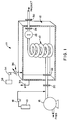
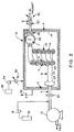
- the reactor 11 of the present invention is shown in Figures 1 and 2. It utilizes a ceramic, titanium, glass, metal alloy, or other corrosion-resistant material or lined composite to contain the supercritical water oxidation reaction in what is termed the “inner reactor”, shown in Figure 1 in a partial perspective view and in Figure 2 as a cross-sectional view as component 10.
- This inner reactor 10 is coupled with what is termed an "outer containment vessel" 12, which is a vessel made of a metal alloy such as carbon steel to contain the pressure.
- the “inner reactor” 10 does not experience an appreciable pressure drop across its walls because the outer vessel 12 acts to surround the inner vessel 10 with an inert, temperature-insulating fluid (such as helium or nitrogen) at approximately the same pressure as the supercritical water oxidation reaction fluid inside the inner reactor 10.
- an inert, temperature-insulating fluid such as helium or nitrogen
- the inner reactor 10 is, in addition, advantageously coated on its outer surface with an appropriate insulating material 14 which will further act to contain the high temperature of the supercritical water oxidation reaction inside the inner reactor 10.
- the insulating material 14 and the temperature-insulating fluid surrounding the inner reactor 10 maintain the outer vessel 12 at a more moderate (lower) temperature, serving to retain its ductility for a longer period.
- the separation of the outer vessel 12 and the inner reactor 10 also serves to restrict the corrosive conditions to the inner reactor's 10 inner wall, protecting the outer vessel 12 from any corrosive conditions.
- Pumps 16 and 18 deliver pressurized reactants, e.g., aqueous organic waste such as pulp mill sludge, municipal sludge, or other aqueous wastes, at ambient temperatures and pressure above about 3000 psi, and, e.g., oxidant supply 13 such as air, oxygen, or hydrogen peroxide, to connector 20, which connects the pumps' piping with the outer vessel 12, and which could be a wedged-type fitting.
- Reactant fluid mixture then flows from connector 20 to connector 22.
- Parts of the 20 and 22 connectors are, in this particular embodiment, continuous with the outer containment vessel 12, and may incorporate appropriate gaskets as needed.
- Connector 22 connects the outer vessel 12 with the inner reactor 10.
- Reactant mixture at point A is heated at the feed preheat zone to appropriate temperatures, e.g., between about 300 and about 500°C, by heating element 24.
- Heating element 24 may be, for example, a battery-powered heating tape or direct resistive heating; or, alternatively, it may be a heat exchanger-type arrangement which would transfer heat from the exothermic heat of reaction, generated further downstream within inner reactor 10, to the feed at the preheat zone.
- Inner reactor 10 may be a plug-flow type reactor or a stirred-tank type reactor, or a variation/combination of the two.
- reactants are exothermically converted to products, e.g., organic carbon is oxidized to carbon dioxide.
- Reaction products exit inner reactor 10 and flow through pressure-reduction valve 26, in which an adiabatic expansion occurs and the pressure and temperature both drop significantly.
- the exit fluid flows out through connectors 28 and 30, and residual heat is removed by appropriate means as desired, e.g., heat exchanger 32. It may be desirable to have pressure reduction valve 26 positioned downstream of connector 28, inside or outside the outer vessel 12, depending on the materials of construction desired for valve 26 and their ability to withstand the pressure drop across the orifice and walls.
- Pump 34 delivers insulating fluid to the inside of outer containment vessel 12 as needed during start-up, run-time, and shut-down, to maintain near-zero pressure drop across the walls of inner reactor 10.
- a cooling means 36 may be employed such as a water-cooled heat exchanger to regulate the temperature of the insulating fluid.
- Make-up tank 38 provides a reservoir of insulating fluid.
- Valve 39 purges insulating fluid from the outer containment vessel 12 as part of the pressure-regulating mechanism.
- FIG. 3 shows, qualitatively, the temperature and pressure profiles along the inner reaction vessel 10. Temperature rises at the reactor preheat zone at point B due to heating element 24, and rises along inner reactor 10 due to the heat released in the exothermic supercritical water oxidation reaction (oxidization of organics to form carbon dioxide and water). The temperature drops at point C pressure reduction valve 26 due to essentially adiabatic expansion of the pressurized fluid. Further heat removal at point D at heat exchanger 32 leads to a further temperature drop. Along the length of the inner reactor 10, there will be a slight pressure drop which serves to move the fluid along the reactor. Also, a significant pressure drop occurs downstream of inner reactor 10 at point C at pressure reduction valve 26.
- Figure 4 shows, qualitatively, the temperature and pressure profiles through the outer containment vessel 12 and through a slice of the inner reactor 10. Moving from left to right on Fig. 4, there is substantial pressure rise at E across the left outer vessel (12) wall, negligible pressure change at F & G across the inner reactor (10) walls, and a large pressure drop to ambient pressure at H across right outer vessel (12) wall.
- Figure 5 shows an alternative embodiment 11a in which inner reactor 10A contains a built-in heat exchanger, with concentric cylinders 50 and 52, which transfers the exothermic heat of reaction to the feed to further preheat the feed stream.
- insulation may be accomplished solely by the insulating fluid surrounding inner reactor/heat exchanger 10A as shown.
- This example illustrates how a commercial supercritical water oxidation system could be built to treat pulp and paper mill sludges.
- the inner reactor is a tubular plug-flow type reactor made of InconelTM X lined with an aluminum-oxide glass or ceramic coating which is stable at temperatures up to at least 700°C.
- This inner reactor is surrounded with temperature-insulating material such as glass wool.
- the outer containment vessel is carbon steel.
- the insulating fluid is nitrogen gas.
- a cooling mechanism exists for the nitrogen gas to keep its temperature below about 100 to 400°C.
- Pressure transducers located inside the inner reactor and inside the outer containment vessel feed a computerized feedback system which operates a series of pumps and valves which serve to regulate the pressure of the outer containment vessel to assure that the pressure drop across the walls of the ceramic inner reaction vessel is maintained below about 5 atm.
- the feed mixture consists of a pulp and/or paper mill sludge slurry containing 80-90% water.
- pure oxygen gas is added in a stoichiometric ratio of about 2:1 and the mixture is subsequently pre-heated to 300-400°C as it enters the inner reactor, where it reacts exothermically to form CO2 and H2O at a temperature in the range of 400-700°C.
- the product mixture Upon leaving the reactor, the product mixture enters a throttling valve, essentially expanding adiabatically and thus lowering its temperature and pressure. Further cooling means via a water-cooled shell-and-tube heat exchanger serves to cool the product stream enough to recover the CO2 and discharge (or store or recycle) the product water.
- the inner reactor may be made of blown glass.
- the inner reactor may contain a built-in heat exchanger which transfers the exothermic heat of reaction to the feed to preheat the feed.
- the insulating fluid may be helium, nitrogen, air, carbon dioxide, or mixtures thereof.
- the feed stream may be municipal sludge.
Landscapes
- Chemical & Material Sciences (AREA)
- Organic Chemistry (AREA)
- Chemical Kinetics & Catalysis (AREA)
- Life Sciences & Earth Sciences (AREA)
- Hydrology & Water Resources (AREA)
- Engineering & Computer Science (AREA)
- Environmental & Geological Engineering (AREA)
- Water Supply & Treatment (AREA)
- Physical Or Chemical Processes And Apparatus (AREA)
Applications Claiming Priority (2)
| Application Number | Priority Date | Filing Date | Title |
|---|---|---|---|
| US26770394A | 1994-06-29 | 1994-06-29 | |
| US267703 | 1994-06-29 |
Publications (1)
| Publication Number | Publication Date |
|---|---|
| EP0689868A1 true EP0689868A1 (fr) | 1996-01-03 |
Family
ID=23019826
Family Applications (1)
| Application Number | Title | Priority Date | Filing Date |
|---|---|---|---|
| EP95109643A Withdrawn EP0689868A1 (fr) | 1994-06-29 | 1995-06-21 | Réacteur pour la réalisation de réactions corrosives sans haute température et haute pression |
Country Status (5)
| Country | Link |
|---|---|
| US (1) | US5932182A (fr) |
| EP (1) | EP0689868A1 (fr) |
| AU (1) | AU692254B2 (fr) |
| CA (1) | CA2138194A1 (fr) |
| TW (1) | TW259720B (fr) |
Cited By (6)
| Publication number | Priority date | Publication date | Assignee | Title |
|---|---|---|---|---|
| WO2001017915A1 (fr) * | 1999-09-03 | 2001-03-15 | Chematur Engineering Ab | Système réactionnel haute pression et haute température |
| BE1014392A3 (fr) * | 1999-03-12 | 2003-10-07 | Phenolchemie Gmbh & Co Kg | Procede pour le demarrage des systemes de reacteur en boucle, dans lesquels au moins une reaction exothermique doit etre realisee. |
| WO2006039317A1 (fr) * | 2004-09-30 | 2006-04-13 | Tokyo Electron Limited | Systeme de traitement d'un fluide supercritique comprenant un revetement sur des elements internes et son procede d'utilisation |
| FR2924358A1 (fr) * | 2007-11-30 | 2009-06-05 | Inst Francais Du Petrole | Nouveau reacteur permettant la mise en oeuvre de reactions a tres haute temperature et haute pression |
| CN107892345A (zh) * | 2017-10-20 | 2018-04-10 | 吴丹丹 | 一种超临界反应装置 |
| WO2019076385A1 (fr) * | 2017-10-20 | 2019-04-25 | 吴丹丹 | Appareil de réaction supercritique à auto-équilibrage horizontal |
Families Citing this family (25)
| Publication number | Priority date | Publication date | Assignee | Title |
|---|---|---|---|---|
| DE19803111A1 (de) * | 1998-01-28 | 1999-08-05 | Volkhard Dr Ing Seiffert | Druckbehälter |
| JP2000189781A (ja) * | 1998-12-28 | 2000-07-11 | Toshiba Corp | 高圧処理装置、高圧処理装置への供給方法および高圧処理装置の保護方法 |
| US6752972B1 (en) | 2000-05-10 | 2004-06-22 | Essox Research And Development, Inc. | Plasma processing method and apparatus |
| US20030124049A1 (en) * | 2001-08-13 | 2003-07-03 | Sowmya Krishnan | Catalytic reactor apparatus and method for generating high purity water vapor |
| US20040232046A1 (en) * | 2001-08-21 | 2004-11-25 | Hiroshi Tanaka | Method and apparatus for recycling hydrocarbon resource |
| US20090028781A1 (en) * | 2002-08-13 | 2009-01-29 | Sowmya Krishnan | Catalytic reactor method for generating high purity water vapor |
| AU2003299763B2 (en) * | 2002-12-26 | 2009-01-22 | Baker Hughes Incorporated | Alternative packer setting method |
| DE10313529A1 (de) * | 2003-03-26 | 2004-10-14 | Basf Ag | Reaktor für Hochtemperaturreaktionen und Verwendung |
| DE10313527A1 (de) * | 2003-03-26 | 2004-10-14 | Basf Ag | Verfahren zur Durchführung einer Hochtemperaturreaktion, Reaktor zur Durchführung des Verfahrens, Verfahren zum Scale-Up eines Reaktors sowie Verwendung |
| JP4334298B2 (ja) * | 2003-08-19 | 2009-09-30 | 株式会社東芝 | 有機廃棄物の処理装置および処理方法 |
| US20050175519A1 (en) * | 2004-02-06 | 2005-08-11 | Rogers William A.Jr. | Microchannel compression reactor |
| ITMI20041240A1 (it) * | 2004-06-21 | 2004-09-21 | 3V Green Eagle S P A | Rivestimento particolare per apparecchiature per realizzare processi ossidativi e apparecchiatura comprendente tale rivestimento |
| GB0500838D0 (en) * | 2005-01-15 | 2005-02-23 | Accentus Plc | Catalytic reactor |
| US7815891B2 (en) * | 2006-01-12 | 2010-10-19 | Kabushiki Kaisha Toshiba | Device and method for producing hydrogen |
| CA2541035A1 (fr) * | 2006-03-27 | 2007-09-27 | Brian H. Harrison | Reacteur pour reduction chimique du caoutchouc |
| US9649612B2 (en) | 2008-09-25 | 2017-05-16 | Rubreco Inc. | Dual vessel reactor |
| MX2011003068A (es) * | 2008-09-25 | 2011-09-26 | Brian H Harrison | Reactor de doble recipiente. |
| TWI428290B (zh) * | 2008-12-03 | 2014-03-01 | Rainer Bauder | 廢水處理系統以及方法(一) |
| US9475029B2 (en) | 2013-08-28 | 2016-10-25 | Louisiana Eco Green, L.L.C. | Method of manufacturing bio-diesel and reactor |
| US10221488B2 (en) * | 2015-09-18 | 2019-03-05 | General Electric Company | Supercritical water method for treating internal passages |
| RU167568U1 (ru) * | 2015-12-31 | 2017-01-10 | Федеральное государственное автономное образовательное учреждение высшего образования "Уральский федеральный университет имени первого Президента России Б.Н. Ельцина" | Автоклав |
| ITUB20160403A1 (it) * | 2016-01-29 | 2017-07-29 | Archimede S R L | Reattore con sistema di compensazione della pressione |
| US10920152B2 (en) | 2016-02-23 | 2021-02-16 | Pyrophase, Inc. | Reactor and method for upgrading heavy hydrocarbons with supercritical fluids |
| PL238324B1 (pl) * | 2017-08-29 | 2021-08-09 | Inst Chemii Organicznej Polskiej Akademii Nauk | Aparatura przepływowa do prowadzenia procesów pod wysokim ciśnieniem w trybie ciągłym |
| JP7571097B2 (ja) * | 2022-09-29 | 2024-10-22 | 本田技研工業株式会社 | 二酸化炭素除去装置 |
Citations (6)
| Publication number | Priority date | Publication date | Assignee | Title |
|---|---|---|---|---|
| DE851356C (de) * | 1950-10-07 | 1952-10-02 | Robert Dr Huegel | Doppelwandige Vakuum- oder Druckapparatur |
| FR1202200A (fr) * | 1957-02-21 | 1960-01-08 | Chemical Construction Corp | Procédé et appareil pour conduire des réactions chimiques à des températures et pressions élevées |
| DE1542005A1 (de) * | 1951-01-28 | 1970-03-19 | Basf Ag | Hochdruckreaktor |
| JPS61242629A (ja) * | 1985-04-19 | 1986-10-28 | Toda Kogyo Corp | 二重殻を備えた高圧オ−トクレ−ブ |
| WO1989001822A1 (fr) * | 1987-09-01 | 1989-03-09 | Thermolytica Corporation | Autoclave ameliore pour dechets tres dangereux |
| US5133877A (en) * | 1991-03-29 | 1992-07-28 | The United States Of America As Represented By The United States Department Of Energy | Conversion of hazardous materials using supercritical water oxidation |
Family Cites Families (20)
| Publication number | Priority date | Publication date | Assignee | Title |
|---|---|---|---|---|
| US4751067A (en) * | 1982-06-22 | 1988-06-14 | Harry Levin | Process for making silicon from halosilanes and halosilicons |
| US4670404A (en) * | 1985-04-22 | 1987-06-02 | Fike Corporation | Micro-scale chemical process simulation methods and apparatus useful for design of full scale processes, emergency relief systems and associated equipment |
| US4869833A (en) * | 1986-04-03 | 1989-09-26 | Vertech Treatment Systems, Inc. | Method and apparatus for controlled chemical reactions |
| US4721575A (en) * | 1986-04-03 | 1988-01-26 | Vertech Treatment Systems, Inc. | Method and apparatus for controlled chemical reactions |
| US4792408A (en) * | 1987-04-13 | 1988-12-20 | James A. Titmas Associates Incorporated | Method and apparatus for enhancing chemical reactions at supercritical conditions |
| US4882128A (en) * | 1987-07-31 | 1989-11-21 | Parr Instrument Company | Pressure and temperature reaction vessel, method, and apparatus |
| DE3743058A1 (de) * | 1987-12-18 | 1989-06-29 | Krupp Gmbh | Verfahren zur kontinuierlichen extraktion von hoch- bzw. nichtsiedenden aber schmelzenden organischen stoffgemischen |
| US5244638A (en) * | 1989-03-21 | 1993-09-14 | The Regents Of The University Of California | High pressure furnace |
| US5198197A (en) * | 1990-07-13 | 1993-03-30 | Isco, Inc. | Apparatus and method for supercritical fluid extraction |
| US5094753A (en) * | 1990-07-13 | 1992-03-10 | Isco, Inc. | Apparatus and method for supercritical fluid extraction |
| US5132014A (en) * | 1990-07-13 | 1992-07-21 | Isco, Inc. | Apparatus and method for supercritical fluid extraction |
| US5160624A (en) * | 1990-07-13 | 1992-11-03 | Isco, Inc. | Apparatus and method for supercritical fluid extraction |
| US5173188A (en) * | 1990-07-13 | 1992-12-22 | Isco, Inc. | Apparatus and method for supercritical fluid extraction |
| WO1992009362A1 (fr) * | 1990-11-23 | 1992-06-11 | Battelle Memorial Institute | Cuve a double paroi et a pression equilibree |
| US5100560A (en) * | 1991-05-31 | 1992-03-31 | Abb Lummus Crest Inc. | Apparatus and method for supercritical water oxidation |
| US5384051A (en) * | 1993-02-05 | 1995-01-24 | Mcginness; Thomas G. | Supercritical oxidation reactor |
| US5387398A (en) * | 1993-12-03 | 1995-02-07 | Aerojet General Corporation | Supercritical water oxidation reactor with wall conduits for boundary flow control |
| US5591415A (en) * | 1994-01-27 | 1997-01-07 | Rpc Waste Management Services, Inc. | Reactor for supercritical water oxidation of waste |
| US5571423A (en) * | 1994-10-14 | 1996-11-05 | Foster Wheeler Development Corporation | Process and apparatus for supercritical water oxidation |
| US5571424A (en) * | 1995-02-27 | 1996-11-05 | Foster Wheeler Development Corporation | Internal platelet heat source and method of use in a supercritical water oxidation reactor |
-
1994
- 1994-11-14 TW TW083110534A patent/TW259720B/zh active
- 1994-12-15 CA CA002138194A patent/CA2138194A1/fr not_active Abandoned
-
1995
- 1995-06-21 EP EP95109643A patent/EP0689868A1/fr not_active Withdrawn
- 1995-06-27 AU AU23289/95A patent/AU692254B2/en not_active Ceased
-
1998
- 1998-02-23 US US09/028,142 patent/US5932182A/en not_active Expired - Fee Related
Patent Citations (6)
| Publication number | Priority date | Publication date | Assignee | Title |
|---|---|---|---|---|
| DE851356C (de) * | 1950-10-07 | 1952-10-02 | Robert Dr Huegel | Doppelwandige Vakuum- oder Druckapparatur |
| DE1542005A1 (de) * | 1951-01-28 | 1970-03-19 | Basf Ag | Hochdruckreaktor |
| FR1202200A (fr) * | 1957-02-21 | 1960-01-08 | Chemical Construction Corp | Procédé et appareil pour conduire des réactions chimiques à des températures et pressions élevées |
| JPS61242629A (ja) * | 1985-04-19 | 1986-10-28 | Toda Kogyo Corp | 二重殻を備えた高圧オ−トクレ−ブ |
| WO1989001822A1 (fr) * | 1987-09-01 | 1989-03-09 | Thermolytica Corporation | Autoclave ameliore pour dechets tres dangereux |
| US5133877A (en) * | 1991-03-29 | 1992-07-28 | The United States Of America As Represented By The United States Department Of Energy | Conversion of hazardous materials using supercritical water oxidation |
Non-Patent Citations (2)
| Title |
|---|
| DATABASE WPI Section Ch Week 8649, Derwent World Patents Index; Class J04, AN 86-323898 * |
| PATENT ABSTRACTS OF JAPAN vol. 11, no. 89 (C - 411) 19 March 1987 (1987-03-19) * |
Cited By (13)
| Publication number | Priority date | Publication date | Assignee | Title |
|---|---|---|---|---|
| BE1014392A3 (fr) * | 1999-03-12 | 2003-10-07 | Phenolchemie Gmbh & Co Kg | Procede pour le demarrage des systemes de reacteur en boucle, dans lesquels au moins une reaction exothermique doit etre realisee. |
| JP4752074B2 (ja) * | 1999-09-03 | 2011-08-17 | ホリングフォード・リミテッド | 高圧高温反応システム |
| US6958122B1 (en) | 1999-09-03 | 2005-10-25 | Chematur Engineering Ab | High pressure and high temperature reaction system |
| WO2001017915A1 (fr) * | 1999-09-03 | 2001-03-15 | Chematur Engineering Ab | Système réactionnel haute pression et haute température |
| WO2006039317A1 (fr) * | 2004-09-30 | 2006-04-13 | Tokyo Electron Limited | Systeme de traitement d'un fluide supercritique comprenant un revetement sur des elements internes et son procede d'utilisation |
| WO2009092876A3 (fr) * | 2007-11-30 | 2009-11-12 | Ifp | Nouveau reacteur permettant la mise en oeuvre de reactions a tres haute temperature et haute pression |
| FR2924358A1 (fr) * | 2007-11-30 | 2009-06-05 | Inst Francais Du Petrole | Nouveau reacteur permettant la mise en oeuvre de reactions a tres haute temperature et haute pression |
| RU2471544C2 (ru) * | 2007-11-30 | 2013-01-10 | Ифп | Новый реактор, позволяющий осуществлять реакции при сверхвысокой температуре и высоком давлении |
| US8858221B2 (en) | 2007-11-30 | 2014-10-14 | IFP Energies Nouvelles | Reactor for carrying out very high temperature and high pressure reactions |
| CN107892345A (zh) * | 2017-10-20 | 2018-04-10 | 吴丹丹 | 一种超临界反应装置 |
| WO2019076385A1 (fr) * | 2017-10-20 | 2019-04-25 | 吴丹丹 | Appareil de réaction supercritique à auto-équilibrage horizontal |
| CN107892345B (zh) * | 2017-10-20 | 2020-12-01 | 吴丹丹 | 一种超临界反应装置 |
| US11136252B2 (en) | 2017-10-20 | 2021-10-05 | Nanjing Since-More Environmental Technology Co, Ltd. | Horizontal self-balancing supercritical reaction apparatus |
Also Published As
| Publication number | Publication date |
|---|---|
| CA2138194A1 (fr) | 1995-12-30 |
| TW259720B (en) | 1995-10-11 |
| AU692254B2 (en) | 1998-06-04 |
| US5932182A (en) | 1999-08-03 |
| AU2328995A (en) | 1996-01-11 |
Similar Documents
| Publication | Publication Date | Title |
|---|---|---|
| US5932182A (en) | Reactor for high temperature, elevated pressure, corrosive reactions | |
| US5552039A (en) | Turbulent flow cold-wall reactor | |
| US4823711A (en) | Thermal decomposition processor and system | |
| US5571424A (en) | Internal platelet heat source and method of use in a supercritical water oxidation reactor | |
| US5461648A (en) | Supercritical water oxidation reactor with a corrosion-resistant lining | |
| US7972573B2 (en) | Supercritical water oxidation apparatus and process | |
| IE922120A1 (en) | Supercritical water oxidation process and apparatus of organics with inorganics | |
| NO20025248L (no) | Ildfast trykkbeholder | |
| US20230348306A1 (en) | Process for the supercritical oxidation of sewage sludge and other waste streams | |
| US6749816B1 (en) | High-pressure treatment apparatus, feeding method thereto and protection method thereof | |
| EP1420877A4 (fr) | Appareil a membrane transporteuse d'ions et procede correspondant | |
| JPH07313987A (ja) | 高圧反応容器装置 | |
| CA2585624C (fr) | Appareil de reformage a la vapeur et procede de reformage a la vapeur utilisant ledit appareil et four industriel | |
| JP4267791B2 (ja) | 超臨界水処理装置 | |
| JP4334162B2 (ja) | 反応容器 | |
| CA2193944C (fr) | Reacteur a parois froides et a ecoulement turbulent | |
| EP0091015B1 (fr) | Méthode pour exploiter des systèmes d'oxidation humide utilisant de l'oxygène pur | |
| JP2001170664A (ja) | 超臨界水処理装置 | |
| JP2817236B2 (ja) | メタノール改質反応装置 | |
| US6544342B1 (en) | Acid bath for removing contaminants from a metallic article | |
| JP4922500B2 (ja) | 超臨界水反応装置 | |
| EP0550522B1 (fr) | Bouchon d'obturation pour caisson de pression | |
| US12359611B1 (en) | Hydrothermal treatment | |
| EP4513124A1 (fr) | Appareil de stockage de milieu chauffant | |
| EP4355473B1 (fr) | Processus d'arrêt et de chauffage d'un réacteur tubulaire pour une réaction catalytique en phase gazeuse |
Legal Events
| Date | Code | Title | Description |
|---|---|---|---|
| PUAI | Public reference made under article 153(3) epc to a published international application that has entered the european phase |
Free format text: ORIGINAL CODE: 0009012 |
|
| AK | Designated contracting states |
Kind code of ref document: A1 Designated state(s): BE DE ES FR GB IT NL SE |
|
| 17P | Request for examination filed |
Effective date: 19960613 |
|
| RAP1 | Party data changed (applicant data changed or rights of an application transferred) |
Owner name: KIMBERLY-CLARK WORLDWIDE, INC. |
|
| 17Q | First examination report despatched |
Effective date: 19980520 |
|
| STAA | Information on the status of an ep patent application or granted ep patent |
Free format text: STATUS: THE APPLICATION IS DEEMED TO BE WITHDRAWN |
|
| 18D | Application deemed to be withdrawn |
Effective date: 19981201 |