EP0689961A2 - Installation d'éclairage pour véhicule et procédé de montage - Google Patents
Installation d'éclairage pour véhicule et procédé de montage Download PDFInfo
- Publication number
- EP0689961A2 EP0689961A2 EP95109576A EP95109576A EP0689961A2 EP 0689961 A2 EP0689961 A2 EP 0689961A2 EP 95109576 A EP95109576 A EP 95109576A EP 95109576 A EP95109576 A EP 95109576A EP 0689961 A2 EP0689961 A2 EP 0689961A2
- Authority
- EP
- European Patent Office
- Prior art keywords
- lights
- lamp
- motor vehicle
- vehicle lighting
- lighting arrangement
- Prior art date
- Legal status (The legal status is an assumption and is not a legal conclusion. Google has not performed a legal analysis and makes no representation as to the accuracy of the status listed.)
- Withdrawn
Links
- 239000003550 marker Substances 0.000 claims description 21
- 238000009413 insulation Methods 0.000 abstract 1
- 238000009434 installation Methods 0.000 description 2
- 239000011810 insulating material Substances 0.000 description 2
- KQZLRWGGWXJPOS-NLFPWZOASA-N 1-[(1R)-1-(2,4-dichlorophenyl)ethyl]-6-[(4S,5R)-4-[(2S)-2-(hydroxymethyl)pyrrolidin-1-yl]-5-methylcyclohexen-1-yl]pyrazolo[3,4-b]pyrazine-3-carbonitrile Chemical compound ClC1=C(C=CC(=C1)Cl)[C@@H](C)N1N=C(C=2C1=NC(=CN=2)C1=CC[C@@H]([C@@H](C1)C)N1[C@@H](CCC1)CO)C#N KQZLRWGGWXJPOS-NLFPWZOASA-N 0.000 description 1
- 230000015572 biosynthetic process Effects 0.000 description 1
- 229940125877 compound 31 Drugs 0.000 description 1
- 238000011161 development Methods 0.000 description 1
- 230000018109 developmental process Effects 0.000 description 1
- 230000035515 penetration Effects 0.000 description 1
- 230000036316 preload Effects 0.000 description 1
Images

Classifications
-
- B—PERFORMING OPERATIONS; TRANSPORTING
- B60—VEHICLES IN GENERAL
- B60Q—ARRANGEMENT OF SIGNALLING OR LIGHTING DEVICES, THE MOUNTING OR SUPPORTING THEREOF OR CIRCUITS THEREFOR, FOR VEHICLES IN GENERAL
- B60Q1/00—Arrangement of optical signalling or lighting devices, the mounting or supporting thereof or circuits therefor
- B60Q1/26—Arrangement of optical signalling or lighting devices, the mounting or supporting thereof or circuits therefor the devices being primarily intended to indicate the vehicle, or parts thereof, or to give signals, to other traffic
- B60Q1/32—Arrangement of optical signalling or lighting devices, the mounting or supporting thereof or circuits therefor the devices being primarily intended to indicate the vehicle, or parts thereof, or to give signals, to other traffic for indicating vehicle sides, e.g. clearance lights
Definitions
- the invention relates to a motor vehicle lighting arrangement with a plurality of electric lights, in particular side marker lights and / or position lights of a truck, which are connected to a power source via a power cable.
- lorries used for freight traffic are provided with numerous other lights in addition to the headlights that serve their own visibility in the dark and the rear lights.
- These include side marker lights, which are arranged at the same height at intervals along both sides of the vehicle and emit to the side and in yellow.
- Side lights which are located at the four upper corners of the vehicle body, are considered as further lights, with the two front lights shining to the front in white and the two rear lights in red to the rear.
- the side marker lights have been mounted with at least two fastening screws, adjusted by loosening at least one nut in order to achieve a horizontal alignment of the generally rectangular lights, regardless of the side wall of the truck to which the lights are attached, and wired through in sequence, why everyone Luminaire routed to the next individual cable and its ends connected to the relevant luminaires.
- the invention is based on the object of designing the motor vehicle lighting arrangement described at the outset in such a way that it can be easily attached quickly and at any point and can be electrically connected.
- the lights or at least one group of lights is assigned a common power cable with two wires, which passes through the lights in series and is each received by a channel in the light housing, which has a cross section adapted to the power cable and protrude into the two tapered contact pins of the luminaire, which penetrate into the power cable running through the channel transverse to the contact pins, making metallic contact with one wire each.
- a single, correspondingly long, non-interrupted power cable can be provided, to which a basically any number of lights can be connected, which can be carried out quickly and accurately without the use of tools.
- a power cable with a corresponding excess length on the floor of the vehicle body can be pulled out in the area of each side marker lamp and inserted into the channel of the relevant lamp base, which is preferably designed as a recess, which - if necessary in connection with attaching (pressing) the lamp - already automatically causes the electrical connection.
- the two-core power cable common to several lights enables lights to be attached to those parts of the vehicle body where the conditions for ground contact are missing or unfavorable.
- Power cables suitable for the use according to the invention with two cores embedded in a rubber-like or foam-like insulating material at a distance from one another are known, for example in the form of flat cables with a rectangular cross section, the tapered contact pins being able to penetrate into the insulating material without any problem into the wire contact.
- a truck 1 is shown with five wheel axles, which has a box-shaped structure 2 which encloses the loading space.
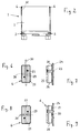
- Six side marker lights 3 are provided on each side of the truck, which are arranged at longitudinal intervals approximately at the top of the vehicle wheels. As can be seen in particular from FIG. 4, the side marker lights 3 have an approximately rectangular shape and are aligned horizontally. The side marker lights 3 are attached to cross sections 4 under the load compartment floor 5.
- position lights 6 also called position lights, are arranged at the upper corners of the structure 2, the two front position lights 6 shining to the front, while the two rear position lights 6 shine to the rear.
- each side marker lamp 3 is provided with an angular mounting bracket 7, which has a mounting leg 8 with two expansion anchors 9, which are pressed through adapted holes in the horizontal leg of the cross section 4 and thus easily achieve a firm fit.
- the downward-pointing support leg 10 of the mounting bracket 7 is provided with a bearing bore 11 through which the lamp base 13 protrudes backwards or inwards from the lamp housing 12.
- the lamp housing 12 receiving the light bulb is closed by a screwed-on cover disk 14.
- the lamp base 13 has a horizontally extending channel 15, which is designed as a rear recess between an upper base web 16 and a lower base web 17. This rear open channel 15 can be closed on its open side by a locking cover 18 which cooperates with resilient locking parts on the two base webs 16 and 17.
- the base webs 16 and 17 form a bearing surface 19 lying on a cylinder jacket, with which the lamp is rotatably mounted in the bearing bore 11.
- the rear-facing base 20 of the lamp housing 12 is provided with an adjustment catch 21, which is indicated in FIG. 5 and can be designed, for example, with a 1 ° angle division. This allows the lamp 3 to be aligned horizontally by appropriate rotation, as shown in FIG. 4, as a result of which inaccuracies in the position of the fastening bracket 7 due to fastening can be compensated for.
- a bracket 22 which is designed as a truncated cone-shaped press ring (spring ring) which is supported at one end on the rear side of the support leg 10 and engages in an annular groove on the lamp base 13 with the other end, for which purpose the spring ring 22 has been deformed or pressed accordingly.
- This press ring or spring ring 22 causes an axial preload, which on the one hand prevents an undesired adjustment of the angular orientation of the lamp 3, but on the other hand enables an angular adjustment of the lamp 3 according to the adjustment catch 21 by hand.
- the spring ring 22 can - like the lamp with its parts 12 to 18 and the mounting bracket 7 with the expansion anchors 9 - be made of a plastic.
- the position lamps 6, like the side marker lamps 3, have an essentially rectangular shape, but are screwed directly onto a carrier part 24 of the structure 2 in a vertical orientation by means of two screws 23.
- the position lamps 6 have a lamp housing 26 provided with a cover plate 25, in the bottom of which two channels intersecting at right angles are formed in the form of depressions, namely a longitudinal channel 27 and a transverse channel 28, which are of the same depth and a common overlap area 29 exhibit.
- a common continuous power cable 30 is provided, which is connected in a conventional manner to the power source of the truck 1 via a switch and extends over the entire length of the structure 2 extends along the bottom 5 thereof.
- the power cable 30 is designed as a flat cable with a rectangular profile, in which two wires 32 and 33 are embedded next to one another at a constant distance, as illustrated in FIG. 4, in a rubber-like or foam-like insulating compound 31.
- each side marker lamp 3 the power cable 30 is pulled out laterally with a cable loop 34 and guided through the channel 15 and held in this position by the retrofitted snap-on cover 18, as illustrated in FIG. 3.
- the lamp housing 12 has two contact pins 35, 36, which project into the channel 15 and each have a pointed end. Accordingly, these contact pins penetrate into the cable 15 when the power cable 30 is inserted into the cable and lead to electrical contact with the wire 32 or 33.
- the front position lamp 6 shown in FIG. 1 can also be connected to the common power cable 30 with a correspondingly long cable loop, unless a separate power cable is provided for the two front position lights. Behind the rear side marker lamp 3, the power cable 30 is led up to the rear marker lamp 6 according to FIG.
- the formation of the position lamp 6 with two intersecting channels 27 and 28 has the advantage that the power cable 30 depending on the intended installation and the lamp arrangement either in the vertical or in the horizontal direction through the lamp housing 26, i.e. either through the longitudinal channel 27 or through the Cross channel 28 can be performed. So that the required double wire contact occurs in both cases, the two contact pins 35 and 36 are provided in the overlap region 29 and with a diagonal arrangement, as is also present in the side marker lights 3 according to FIGS. 4 and 5.
- the motor vehicle lighting arrangement can be attached and connected electrically in a particularly simple manner, largely by hand without the use of special tools. It is even possible to supply all lights 3 and 6 on both sides of the truck 1 with a single continuous power cable 30. Alternatively, a separate power cable can of course also be provided for each side of the vehicle, which then ends at the relevant rear position lamp 6.
Landscapes
- Engineering & Computer Science (AREA)
- Mechanical Engineering (AREA)
- Lighting Device Outwards From Vehicle And Optical Signal (AREA)
- Non-Portable Lighting Devices Or Systems Thereof (AREA)
Applications Claiming Priority (2)
| Application Number | Priority Date | Filing Date | Title |
|---|---|---|---|
| DE4422393 | 1994-06-27 | ||
| DE19944422393 DE4422393C2 (de) | 1994-06-27 | 1994-06-27 | Kraftfahrzeugbeleuchtungsanordnung und Verfahren zu ihrer Anbringung |
Publications (2)
| Publication Number | Publication Date |
|---|---|
| EP0689961A2 true EP0689961A2 (fr) | 1996-01-03 |
| EP0689961A3 EP0689961A3 (fr) | 1996-09-18 |
Family
ID=6521571
Family Applications (1)
| Application Number | Title | Priority Date | Filing Date |
|---|---|---|---|
| EP95109576A Withdrawn EP0689961A3 (fr) | 1994-06-27 | 1995-06-21 | Installation d'éclairage pour véhicule et procédé de montage |
Country Status (2)
| Country | Link |
|---|---|
| EP (1) | EP0689961A3 (fr) |
| DE (2) | DE4422393C2 (fr) |
Cited By (6)
| Publication number | Priority date | Publication date | Assignee | Title |
|---|---|---|---|---|
| EP1632392A1 (fr) * | 2004-09-07 | 2006-03-08 | Schmitz Gotha Fahrzeugwerke GmbH | Ensemble de feux arrière |
| DE102004036340A1 (de) * | 2004-07-27 | 2006-03-23 | Schmitz Gotha Fahrzeugwerke Gmbh | Heckleuchtenanordnung für Lastfahrzeuge, insbesondere Anhänger |
| EP1621409A3 (fr) * | 2004-07-27 | 2006-05-17 | Schmitz Gotha Fahrzeugwerke GmbH | Arrangement d'illumination pour véhicule utilitaire, especialement pour une remorque, et raccord de câbles pour cela |
| EP1690735A1 (fr) * | 2005-02-11 | 2006-08-16 | Schmitz Gotha Fahrzeugwerke GmbH | Dispositif d'éclairage pour un véhicule |
| EP2495130A1 (fr) | 2011-03-02 | 2012-09-05 | Przetworstwo Tworzyw Sztucznych Was Jozef I Leszek was, Spolka Jawna | Lampe d'indication de contour ou lampe de stationnement |
| EP3415368A1 (fr) * | 2017-06-17 | 2018-12-19 | "WIELTON" Spolka Akcyjna | Support pour feux de position latéraux |
Families Citing this family (5)
| Publication number | Priority date | Publication date | Assignee | Title |
|---|---|---|---|---|
| DE19837553A1 (de) * | 1998-08-19 | 2000-02-24 | Hella Kg Hueck & Co | Fahrzeugleuchte |
| DE10159064B4 (de) * | 2001-12-01 | 2005-10-13 | Hella Kgaa Hueck & Co. | Fahrzeugleuchte |
| DE102004046763A1 (de) * | 2004-09-24 | 2006-03-30 | Schmitz-Gotha Fahrzeugwerke Gmbh | Fahrzeug-Leuchtenanordnung, insbesondere für Anhänger |
| DE102007006263A1 (de) | 2007-02-08 | 2008-08-14 | Daimler Ag | Seitenbeleuchtung für einen Lastkraftwagen |
| DE102018101353A1 (de) * | 2018-01-22 | 2019-07-25 | Schmitz Cargobull Ag | Nutzfahrzeugaufbau mit elektrischem Funktionsteil und Verfahren zur Herstellung eines solchen Nutzfahrzeugs |
Family Cites Families (13)
| Publication number | Priority date | Publication date | Assignee | Title |
|---|---|---|---|---|
| DE7508503U (de) * | 1975-07-10 | Adels T Elektro U Waermetechnik | Durchgangsverdrahtvorrichtung für Lichtbänder | |
| US3087051A (en) * | 1960-08-11 | 1963-04-23 | Pullman Inc | Marker lights for roadway vehicles |
| US3107061A (en) * | 1960-10-10 | 1963-10-15 | King Bee Mfg Co | Vehicle lighting system |
| US3218448A (en) * | 1962-10-18 | 1965-11-16 | Truck Lite Co | Lamp mounting bracket |
| US3225185A (en) * | 1964-02-10 | 1965-12-21 | Pullman Inc | Mounting for marker light |
| US3230494A (en) * | 1964-07-08 | 1966-01-18 | Pullman Inc | Clearance marker light |
| US3474381A (en) * | 1967-09-27 | 1969-10-21 | Truck Lite Co | Lamp connection and mounting devices |
| FR2025323A5 (fr) * | 1969-10-27 | 1970-09-04 | Philips France | |
| US3783265A (en) * | 1972-11-06 | 1974-01-01 | Pullman Inc | Adapter for marker light |
| US4079442A (en) * | 1976-08-02 | 1978-03-14 | K-D Lamp Company | Side marker and clearance lamp and mounting apparatus therefor |
| US5025350A (en) * | 1990-04-25 | 1991-06-18 | Federal-Mogul Corporation | Vehicle clearance lamp assembly |
| DE4032140A1 (de) * | 1990-10-10 | 1992-04-16 | Kleinhuis Hermann Gmbh | Elektrische illuminationsfassung |
| US5152599A (en) * | 1991-07-31 | 1992-10-06 | Wilson Trailer Company | Contact strip lighting system |
-
1994
- 1994-06-27 DE DE19944422393 patent/DE4422393C2/de not_active Expired - Fee Related
-
1995
- 1995-03-09 DE DE29504118U patent/DE29504118U1/de not_active Expired - Lifetime
- 1995-06-21 EP EP95109576A patent/EP0689961A3/fr not_active Withdrawn
Non-Patent Citations (1)
| Title |
|---|
| None |
Cited By (7)
| Publication number | Priority date | Publication date | Assignee | Title |
|---|---|---|---|---|
| DE102004036340A1 (de) * | 2004-07-27 | 2006-03-23 | Schmitz Gotha Fahrzeugwerke Gmbh | Heckleuchtenanordnung für Lastfahrzeuge, insbesondere Anhänger |
| EP1621409A3 (fr) * | 2004-07-27 | 2006-05-17 | Schmitz Gotha Fahrzeugwerke GmbH | Arrangement d'illumination pour véhicule utilitaire, especialement pour une remorque, et raccord de câbles pour cela |
| EP1632392A1 (fr) * | 2004-09-07 | 2006-03-08 | Schmitz Gotha Fahrzeugwerke GmbH | Ensemble de feux arrière |
| DE102004043083A1 (de) * | 2004-09-07 | 2006-03-09 | Schmitz Gotha Fahrzeugwerke Gmbh | Heckleuchtenanordnung |
| EP1690735A1 (fr) * | 2005-02-11 | 2006-08-16 | Schmitz Gotha Fahrzeugwerke GmbH | Dispositif d'éclairage pour un véhicule |
| EP2495130A1 (fr) | 2011-03-02 | 2012-09-05 | Przetworstwo Tworzyw Sztucznych Was Jozef I Leszek was, Spolka Jawna | Lampe d'indication de contour ou lampe de stationnement |
| EP3415368A1 (fr) * | 2017-06-17 | 2018-12-19 | "WIELTON" Spolka Akcyjna | Support pour feux de position latéraux |
Also Published As
| Publication number | Publication date |
|---|---|
| EP0689961A3 (fr) | 1996-09-18 |
| DE4422393A1 (de) | 1996-01-11 |
| DE4422393C2 (de) | 1997-07-03 |
| DE29504118U1 (de) | 1996-01-04 |
Similar Documents
| Publication | Publication Date | Title |
|---|---|---|
| EP1069371B1 (fr) | Dispositif à diodes électroluminescentes | |
| DE3880470T2 (de) | Armatur fuer treibhausbeleuchtung. | |
| DE19634309A1 (de) | Leitungshalter mit Aufnahmebereich zum beiderseitigen Aufstecken auf einen Gewindebolzen | |
| DE112010002603T5 (de) | Modulare Antennenanordung für Lokomotiven | |
| DE102004062039B3 (de) | Elektrische Steckdose | |
| EP0689961A2 (fr) | Installation d'éclairage pour véhicule et procédé de montage | |
| DE3902124C2 (fr) | ||
| WO2013171305A1 (fr) | Module de connexion, module d'alimentation en énergie électrique et ensemble de connexion de bandes lumineuses | |
| DE202009003250U1 (de) | Aus mehreren Kennzeichnungsvorrichtungen zusammenstellbare Kennzeichnungs-Reihenanordnung | |
| EP3180561B1 (fr) | Rail guide-roue et installation de traitement de véhicule | |
| DE10319510A1 (de) | Stromschienensystem für Leuchten und Verriegelungselement zur Verwendung in einem Stromschienensystem | |
| DE102019112536A1 (de) | Verbinder zur stirnseitigen Verbindung von Leuchtentragschienen | |
| EP0921595B1 (fr) | Boíte de jonction | |
| DE4017208A1 (de) | Drehstromgenerator fuer fahrzeuge u. dgl. | |
| DE102004005914A1 (de) | Elektronisches Gerät zur Befestigung an einem Fahrzeugteil eines Fahrzeuges | |
| EP1632392B1 (fr) | Ensemble de feux arrière | |
| DE9406388U1 (de) | Mastverbindung für eine Mastleuchte | |
| DE9102953U1 (de) | Durchführungsklemme für Vergußtransformatoren | |
| DE69517847T2 (de) | Kupplungsstücke zur mechanischen und elektrischen Verbindung von Stromschienen | |
| EP3763992A1 (fr) | Système d'éclairage ainsi que support d'appareil pour un tel système d'éclairage | |
| DE102019130002A1 (de) | Kennzeichenhalter | |
| DE102021109939A1 (de) | Modul für eine Leuchte, insbesondere für eine Lichtbandleuchte | |
| DE102024132236A1 (de) | Federelastisches Montageelement für langgestreckte Deckenleuchten | |
| WO2020182572A1 (fr) | Unité de montage pourvue d'au moins un guide de lumière et d'au moins une carte de circuits imprimés présentant au moins un moyen d'éclairage ainsi que moyen d'éclairage pour fabriquer une telle unité de montage | |
| DE102012107907A1 (de) | Leuchtenmodul und Verfahren zu dessen Montage |
Legal Events
| Date | Code | Title | Description |
|---|---|---|---|
| PUAI | Public reference made under article 153(3) epc to a published international application that has entered the european phase |
Free format text: ORIGINAL CODE: 0009012 |
|
| AK | Designated contracting states |
Kind code of ref document: A2 Designated state(s): AT BE CH DE DK ES FR GB GR IE IT LI LU MC NL PT SE |
|
| AX | Request for extension of the european patent |
Free format text: LT PAYMENT 950721;LV PAYMENT 950721;SI PAYMENT 950721 |
|
| RAX | Requested extension states of the european patent have changed |
Free format text: LT PAYMENT 950721;LV PAYMENT 950721;SI PAYMENT 950721 |
|
| PUAL | Search report despatched |
Free format text: ORIGINAL CODE: 0009013 |
|
| AK | Designated contracting states |
Kind code of ref document: A3 Designated state(s): AT BE CH DE DK ES FR GB GR IE IT LI LU MC NL PT SE |
|
| AX | Request for extension of the european patent |
Free format text: LT PAYMENT 950721;LV PAYMENT 950721;SI PAYMENT 950721 |
|
| 17P | Request for examination filed |
Effective date: 19970318 |
|
| 17Q | First examination report despatched |
Effective date: 19980625 |
|
| STAA | Information on the status of an ep patent application or granted ep patent |
Free format text: STATUS: THE APPLICATION IS DEEMED TO BE WITHDRAWN |
|
| 18D | Application deemed to be withdrawn |
Effective date: 19990504 |