EP0689988A1 - Dérailleur, notamment pour bicyclettes - Google Patents
Dérailleur, notamment pour bicyclettes Download PDFInfo
- Publication number
- EP0689988A1 EP0689988A1 EP95110130A EP95110130A EP0689988A1 EP 0689988 A1 EP0689988 A1 EP 0689988A1 EP 95110130 A EP95110130 A EP 95110130A EP 95110130 A EP95110130 A EP 95110130A EP 0689988 A1 EP0689988 A1 EP 0689988A1
- Authority
- EP
- European Patent Office
- Prior art keywords
- chain
- sprocket
- tooth
- teeth
- unit
- Prior art date
- Legal status (The legal status is an assumption and is not a legal conclusion. Google has not performed a legal analysis and makes no representation as to the accuracy of the status listed.)
- Granted
Links
- 235000000621 Bidens tripartita Nutrition 0.000 claims abstract description 10
- 240000004082 Bidens tripartita Species 0.000 claims abstract description 10
- 208000006637 fused teeth Diseases 0.000 claims abstract description 10
- 230000007704 transition Effects 0.000 claims description 35
- 238000007373 indentation Methods 0.000 claims description 5
- 230000002093 peripheral effect Effects 0.000 claims 1
- 238000000034 method Methods 0.000 description 5
- 230000008569 process Effects 0.000 description 5
- 230000008901 benefit Effects 0.000 description 2
- 230000007547 defect Effects 0.000 description 2
- 238000004049 embossing Methods 0.000 description 2
- 230000001154 acute effect Effects 0.000 description 1
- 230000008859 change Effects 0.000 description 1
- 230000000694 effects Effects 0.000 description 1
- 230000002349 favourable effect Effects 0.000 description 1
- 230000007246 mechanism Effects 0.000 description 1
Images




Classifications
-
- B—PERFORMING OPERATIONS; TRANSPORTING
- B62—LAND VEHICLES FOR TRAVELLING OTHERWISE THAN ON RAILS
- B62M—RIDER PROPULSION OF WHEELED VEHICLES OR SLEDGES; POWERED PROPULSION OF SLEDGES OR SINGLE-TRACK CYCLES; TRANSMISSIONS SPECIALLY ADAPTED FOR SUCH VEHICLES
- B62M9/00—Transmissions characterised by use of an endless chain, belt, or the like
- B62M9/04—Transmissions characterised by use of an endless chain, belt, or the like of changeable ratio
- B62M9/06—Transmissions characterised by use of an endless chain, belt, or the like of changeable ratio using a single chain, belt, or the like
- B62M9/10—Transmissions characterised by use of an endless chain, belt, or the like of changeable ratio using a single chain, belt, or the like involving different-sized wheels, e.g. rear sprocket chain wheels selectively engaged by the chain, belt, or the like
Definitions
- the invention relates to a derailleur, in particular for bicycles, comprising a driving sprocket unit and a driven sprocket unit and a chain connecting these two sprocket units, at least one of the sprocket units being designed as a multi-sprocket unit with at least two sprockets, namely a larger and a smaller sprocket is further, the two sprockets of the multi-sprocket unit each have a plurality of teeth and at least one tooth gap formed between a pair of teeth, the chain of consecutive chain links and of inner and outer link pairs is formed in an alternating order between the chain links, further to Turning the chain between the two sprockets of the multi-sprocket unit a folding device is provided in an inlet area, which the chain with the normal direction of rotation of the chain and the sprockets he runs into the multi-sprocket unit and this transfer device is designed to give the chain movements in a direction parallel to the
- Deraille are already known (DE-OS 39 36 921), in which the sprocket arrangement consists of at least one large sprocket with teeth and a small sprocket with teeth, which are adjacent to one another and can optionally be engaged in a bicycle drive chain, which consists of a row of hinged connecting plates closed to form a loop.
- the teeth of the small sprocket have such a phase relationship with respect to the chain receiving portion of the large sprocket that a tooth of the small sprocket located below the reference tooth engages the chain when the connecting portion of the chain and the chain receiving portion of the reference tooth is recorded.
- a cut-out area, i.e. shortened teeth, is provided for the perfect chain changing process from the small to the large chain wheel.
- Deflection chamfers are attached in front of these teeth, so that switching can only take place when the chain is laterally deflected and extends over the shortened teeth of the smaller and next larger gearwheel.
- the disadvantage here is that longer lengths are required for switching in the circumferential direction, and that, especially with small sprockets for switching from the larger to the smaller sprocket, no corresponding space requirement can be provided for such a switching point.
- Such a switching point requires several teeth arranged one after the other on the larger ring gear, which have a special shape (Chamfer, ramps, bevel). Furthermore, there is increased wear on the toothed rings due to the shortened teeth.
- the invention has for its object to enable a further ease of transition, in particular from the larger sprocket to the small sprocket, but possibly also from the smaller sprocket to the larger sprocket, even with small differences in the number of teeth.
- the tooth arranged in the circumferential direction in front of the tooth space, seen in the axial direction is externally an indentation, consisting of a circumferential, outward-facing surface for supporting the inner chain link and a perpendicularly inclined passage of the chain serving surface and / or that in the circumferential direction of the second tooth following the tooth gap has an indentation, consisting of a circumferentially extending, outward-facing surface for supporting the chain inner link plates and a perpendicular to the passage of the chain serving surface.
- the advantage here is that a safe gear change to the smaller sprockets is possible.
- the tip circle of the next smaller sprocket is only slightly smaller than the tip circle of the output sprocket.
- the indentations or switching ramps are applied to both the tooth leading the tooth gap in the circumferential direction and the second tooth following the tooth gap in the axial direction, so that when the switching mechanism is deflected, the inner link plates on the aforementioned impressions or Lay switching ramps and thus overcome the tip circle of the smaller gear rim at precisely coordinated points.
- a favorable embodiment provides that the tooth having the bevel follows a tooth with an indentation, seen in the axial direction and externally arranged, in the circumferential direction.
- Another embodiment provides that the tooth having the bevel leads a tooth gap in the circumferential direction.
- one of the shift gates on the larger sprocket is provided with a tooth gap leading by a central angle on the smaller sprocket, so that the catch tooth required on the smaller sprocket can simultaneously be used as an active switching switch for the larger sprocket.
- At least one recess is provided between two successive teeth of a sprocket, the tooth base in the roller bearing area of the tooth gap having an increase compared to the root circle of the other tooth bases at least in the area trailing in the circumferential direction.
- a chain elongation compensation is provided in the area of the tooth gap, which ensures that the chain runs smoothly through the tooth gap.
- chain elongation compensation can no longer be carried out by changing the central angle.
- a chain which connects the rear wheel sprocket set with a pedal crank sprocket set of the bicycle, is designated by B.
- the chain B runs into the sprocket set A, C via the idler 10 of a chain thrower device.
- the normal chain circumferential direction corresponding to the forward drive is indicated by the arrow 11.
- Pedal crank sprocket set tangentially running, upper chain link, at 15 the entry of chain B is shown in the rear wheel sprocket set.
- Fig. 1 shows the switching process from the smaller sprocket C to the larger sprocket A. It can be seen in the upper half of Fig. 1 that the chain B is still engaged with the smaller sprocket C. In the lower half of Fig. 1 it can be seen that part of the chain B already rests on the larger sprocket A.
- the transition of the chain B from the smaller sprocket C to the large sprocket A has been initiated by moving the guide wheel 10 perpendicular to the plane of the drawing at an earlier point in time than the state of FIG. 1 at which the tooth A1 of the large Sprocket A was still in front of the area of the stator 10.
- This transition zone moves in the direction of rotation 11 when the sprocket set A, C continues to rotate. If the trailing end T1 of the transition zone T comes into the drainage area L according to FIG. 1, in which the chain B detaches from the chain wheel set in order to approach the sprocket-side chain wheel set, then the switching process from the smaller chain wheel C to the large chain wheel A is ended.
- a chain link point B1 can be seen in FIG. 2, which shows the transition region T enlarged.
- This chain pivot point B1 is formed in the usual way by a bolt 13 and a chain roller 14.
- the chain articulation point B1 is the chain articulation point that is still fully engaged before the switching movement of the stator wheel 10 takes effect the small sprocket C, in a tooth gap between the teeth C1 and C2 of the small sprocket C.
- the chain link point B5, which is designed in the same way as the chain link point B1, is the first chain link point which, after the switching movement of the guide wheel 10 in full engagement with the large sprocket A, namely in the tooth gap between the two teeth A4 and A5 of the large sprocket A.
- the large sprocket A has a tooth defect between the successive teeth A2 and A4, which is designated A3.
- the small sprocket C also has a missing tooth C3 between its teeth C2 and C4.
- the two defects A3 and C3 result in enlarged tooth gaps ZA and ZC.
- These tooth gaps ZA and ZC facilitate the transition of the chain B from the small sprocket C to the large sprocket A.
- the chain roller 14 of the chain hinge point B1 is still fully engaged with two successive teeth C1 and C2 of the small chain wheel C.
- the chain roller 14 of the hinge point B2 has already been somewhat removed from the enlarged tooth gap ZC.
- the chain link point B3 is therefore perpendicular to the plane of the drawing in FIG.
- the tooth A4 engages between the two link plates of the outer link plate pair D5a
- the chain link point B5 is the first link point which engages with its chain roller 14 between two successive teeth A4 and A5 of the large chain wheel A. It can be seen in FIG.
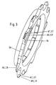
- a single sprocket in which the tooth leading to the tooth gap ZA is provided with an embossing, the outward surface A7 supporting the inner chain link and the inclined surface A8 of the passage of the chain from the larger to the smaller sprocket guaranteed.
- the second tooth following the tooth gap ZA is also provided with an outwardly facing surface A7 and a surface A8 which runs obliquely thereto.
- Fig. 4 shows a ring gear from the front, wherein one of the teeth on its rear side has a bevel A9, this bevel on the back of tooth A9 faces the adjacent larger ring gear and together with a bracket 16 on this ring gear serves to form a Alley for the chain for switching from the small sprocket to the large sprocket.
- the surface A7 and the surface A8 running obliquely thereto according to FIG. 3 support the switching process from the larger sprocket to the smaller sprocket.
- FIG. 5 shows a section of a ring gear in which an increase 18 over the root diameter 19 was made in the tooth gap ZA.
- this root circle elevation 18 serves to compensate for chain elongation.
- the elevation 18 is dimensioned such that pivoting the chain roller in and out of the chain no longer differs from the behavior of standard teeth.
Landscapes
- Engineering & Computer Science (AREA)
- Chemical & Material Sciences (AREA)
- Combustion & Propulsion (AREA)
- Transportation (AREA)
- Mechanical Engineering (AREA)
- Gears, Cams (AREA)
- Transmissions By Endless Flexible Members (AREA)
- Devices For Conveying Motion By Means Of Endless Flexible Members (AREA)
Applications Claiming Priority (2)
| Application Number | Priority Date | Filing Date | Title |
|---|---|---|---|
| DE4434752 | 1994-06-29 | ||
| DE4434752A DE4434752A1 (de) | 1994-09-29 | 1994-09-29 | Kettenschaltung, insbesondere für Fahrräder |
Publications (2)
| Publication Number | Publication Date |
|---|---|
| EP0689988A1 true EP0689988A1 (fr) | 1996-01-03 |
| EP0689988B1 EP0689988B1 (fr) | 1997-11-12 |
Family
ID=6529472
Family Applications (1)
| Application Number | Title | Priority Date | Filing Date |
|---|---|---|---|
| EP95110130A Expired - Lifetime EP0689988B1 (fr) | 1994-06-29 | 1995-06-29 | Dérailleur, notamment pour bicyclettes |
Country Status (3)
| Country | Link |
|---|---|
| EP (1) | EP0689988B1 (fr) |
| CN (1) | CN1054909C (fr) |
| DE (2) | DE4434752A1 (fr) |
Cited By (5)
| Publication number | Priority date | Publication date | Assignee | Title |
|---|---|---|---|---|
| US6340338B1 (en) | 2000-09-13 | 2002-01-22 | Shimano Inc. | Bicycle sprocket |
| EP1439118A3 (fr) * | 2003-01-17 | 2005-04-06 | Shimano Inc. | Pignon de bicyclette ayant des protubérances latérales à utiliser dans un ensemble de pignons |
| EP1342657A3 (fr) * | 2002-03-08 | 2006-03-29 | Shimano Inc. | Ensemble de jeu de pignons à chaîne pour bicyclette |
| US8066603B2 (en) | 2007-09-21 | 2011-11-29 | Sram Deutschland Gmbh | Multi-speed sprocket assembly |
| CN105644700A (zh) * | 2014-10-14 | 2016-06-08 | Sram德国有限公司 | 用于后轮毂的多链轮装置 |
Families Citing this family (10)
| Publication number | Priority date | Publication date | Assignee | Title |
|---|---|---|---|---|
| DE10119590A1 (de) * | 2001-04-21 | 2002-10-24 | Sram De Gmbh | Kettenrad für Rollenketten |
| DE10256746A1 (de) * | 2002-12-05 | 2004-06-24 | Hans Helmig Gmbh | Schaltungskettenräder |
| DE10347784B4 (de) * | 2003-10-10 | 2017-04-06 | Sram Deutschland Gmbh | Geräuscharme Kettenschaltung |
| DE102006010498A1 (de) * | 2006-03-07 | 2007-09-13 | Sram Deutschland Gmbh | Mehrfachkettenradeinheit und Kettenschaltung, insbesondere für Fahrräder |
| DE102010023881B4 (de) | 2010-06-15 | 2015-07-30 | MXC UG (haftungsbeschränkt) | Kettenrad |
| DE202010009083U1 (de) | 2010-06-15 | 2011-11-14 | MXC UG (haftungsbeschränkt) | Kettenrad |
| DE102010023882B4 (de) * | 2010-06-15 | 2015-08-06 | MXC UG (haftungsbeschränkt) | Kettenrad |
| US9086138B1 (en) * | 2014-01-14 | 2015-07-21 | Shimano Inc. | Bicycle sprocket |
| US10295040B2 (en) * | 2016-10-20 | 2019-05-21 | Shimano Inc. | Bicycle sprocket and bicycle crank assembly |
| US11338887B2 (en) * | 2019-02-21 | 2022-05-24 | Shimano Inc. | Bicycle rear sprocket |
Citations (9)
| Publication number | Priority date | Publication date | Assignee | Title |
|---|---|---|---|---|
| GB2005363A (en) * | 1977-08-19 | 1979-04-19 | Shimano Industrial Co | Multi-speed sprocket and bicycle with such a sprocket |
| EP0008851A1 (fr) * | 1978-07-07 | 1980-03-19 | Shimano Industrial Company Limited | Pignon de chaîne pour bicyclette |
| FR2467135A1 (fr) * | 1979-10-11 | 1981-04-17 | Shimano Industrial Co | Ensemble de pignons a plusieurs vitesses pour une bicyclette |
| DE3936921A1 (de) | 1988-11-07 | 1990-05-10 | Shimano Industrial Co | Mehrgang-kettenradanordnung fuer fahrraeder |
| EP0429007A1 (fr) * | 1989-11-21 | 1991-05-29 | Campagnolo S.R.L. | Pignon pour bicyclettes et une roue libre pour bicyclettes munies de tels pignons |
| FR2657134A1 (fr) * | 1989-11-03 | 1991-07-19 | Sachs Ind Sa | Ensemble de pignons ou plateaux multiples pour cycle notamment. |
| EP0444645A1 (fr) * | 1990-02-28 | 1991-09-04 | Shimano Inc. | Ensemble de jeu de pignons à chaîne pour bicyclette |
| EP0474139A1 (fr) * | 1990-09-04 | 1992-03-11 | Shimano Inc. | Ensemble de jeu de pignons à chaine pour bicyclette |
| EP0642972A1 (fr) * | 1993-09-13 | 1995-03-15 | FICHTEL & SACHS AG | Changement de vitesse à dérailleur de chaîne, spécialement pour bicyclette |
Family Cites Families (3)
| Publication number | Priority date | Publication date | Assignee | Title |
|---|---|---|---|---|
| GB475021A (en) * | 1937-06-15 | 1937-11-11 | Ervin Vantoch | Improvements in change speed gears for chain drives |
| US4773893A (en) * | 1987-04-20 | 1988-09-27 | Te-Sheng Chang | Sprocket tooth speed varying sprocket assembly |
| EP0313345B1 (fr) * | 1987-10-21 | 1994-01-12 | Shimano Industrial Company Limited | Ensemble de jeu de pignons à chaîne pour bicyclette |
-
1994
- 1994-09-29 DE DE4434752A patent/DE4434752A1/de not_active Withdrawn
-
1995
- 1995-06-29 DE DE59500971T patent/DE59500971D1/de not_active Expired - Lifetime
- 1995-06-29 EP EP95110130A patent/EP0689988B1/fr not_active Expired - Lifetime
- 1995-09-29 CN CN95117115A patent/CN1054909C/zh not_active Expired - Fee Related
Patent Citations (9)
| Publication number | Priority date | Publication date | Assignee | Title |
|---|---|---|---|---|
| GB2005363A (en) * | 1977-08-19 | 1979-04-19 | Shimano Industrial Co | Multi-speed sprocket and bicycle with such a sprocket |
| EP0008851A1 (fr) * | 1978-07-07 | 1980-03-19 | Shimano Industrial Company Limited | Pignon de chaîne pour bicyclette |
| FR2467135A1 (fr) * | 1979-10-11 | 1981-04-17 | Shimano Industrial Co | Ensemble de pignons a plusieurs vitesses pour une bicyclette |
| DE3936921A1 (de) | 1988-11-07 | 1990-05-10 | Shimano Industrial Co | Mehrgang-kettenradanordnung fuer fahrraeder |
| FR2657134A1 (fr) * | 1989-11-03 | 1991-07-19 | Sachs Ind Sa | Ensemble de pignons ou plateaux multiples pour cycle notamment. |
| EP0429007A1 (fr) * | 1989-11-21 | 1991-05-29 | Campagnolo S.R.L. | Pignon pour bicyclettes et une roue libre pour bicyclettes munies de tels pignons |
| EP0444645A1 (fr) * | 1990-02-28 | 1991-09-04 | Shimano Inc. | Ensemble de jeu de pignons à chaîne pour bicyclette |
| EP0474139A1 (fr) * | 1990-09-04 | 1992-03-11 | Shimano Inc. | Ensemble de jeu de pignons à chaine pour bicyclette |
| EP0642972A1 (fr) * | 1993-09-13 | 1995-03-15 | FICHTEL & SACHS AG | Changement de vitesse à dérailleur de chaîne, spécialement pour bicyclette |
Cited By (7)
| Publication number | Priority date | Publication date | Assignee | Title |
|---|---|---|---|---|
| US6340338B1 (en) | 2000-09-13 | 2002-01-22 | Shimano Inc. | Bicycle sprocket |
| EP1342657A3 (fr) * | 2002-03-08 | 2006-03-29 | Shimano Inc. | Ensemble de jeu de pignons à chaîne pour bicyclette |
| EP1439118A3 (fr) * | 2003-01-17 | 2005-04-06 | Shimano Inc. | Pignon de bicyclette ayant des protubérances latérales à utiliser dans un ensemble de pignons |
| US7044876B2 (en) | 2003-01-17 | 2006-05-16 | Shimano, Inc. | Bicycle sprocket having lateral protrusions for use in a multiple sprocket assembly |
| US8066603B2 (en) | 2007-09-21 | 2011-11-29 | Sram Deutschland Gmbh | Multi-speed sprocket assembly |
| CN105644700A (zh) * | 2014-10-14 | 2016-06-08 | Sram德国有限公司 | 用于后轮毂的多链轮装置 |
| CN105644700B (zh) * | 2014-10-14 | 2019-11-22 | Sram德国有限公司 | 用于后轮毂的多链轮装置 |
Also Published As
| Publication number | Publication date |
|---|---|
| DE4434752A1 (de) | 1996-04-04 |
| EP0689988B1 (fr) | 1997-11-12 |
| DE59500971D1 (de) | 1997-12-18 |
| CN1129779A (zh) | 1996-08-28 |
| CN1054909C (zh) | 2000-07-26 |
Similar Documents
| Publication | Publication Date | Title |
|---|---|---|
| EP0689988B1 (fr) | Dérailleur, notamment pour bicyclettes | |
| EP0642972A1 (fr) | Changement de vitesse à dérailleur de chaîne, spécialement pour bicyclette | |
| DE69016320T2 (de) | Kettenradsatz für Fahrrad. | |
| DE4396847C2 (de) | Fahrrad-Mehrfachzahnkranzanordnung | |
| DE69124901T2 (de) | Zusammenbau eines mehrstufigen Kettenrades für ein Fahrrad | |
| DE19606667C2 (de) | Kettenschaltung für Fahrräder | |
| EP3770054B1 (fr) | Agencement de roue dentée multiple pour un moyeu arrière | |
| EP0856461B1 (fr) | Changement de vitesse à chaíne pour bicyclette | |
| DE4445035C1 (de) | Kettenschaltung | |
| DE4418407C2 (de) | Kettenritzelanordnung für Fahrräder | |
| DE69205719T2 (de) | Zusammenbau eines mehrstufigen Kettenrades für ein Fahrrad. | |
| DE3936921C2 (de) | Mehrgang-Kettenradanordnung für Fahrräder | |
| DE3610482C2 (fr) | ||
| DE102007045424A1 (de) | Mehrfachkettenradeinheit für Fahrräder | |
| DE2837270A1 (de) | Mehrfach-kettenraeder fuer ein fahrrad | |
| DE2535943B2 (de) | Kettenradsatz fuer ein fahrrad | |
| EP3988818A1 (fr) | Accouplement de pignons pour bicyclette à résistance élevée à l'usure et ensemble de jeu de pignons doté d'un tel accouplement | |
| EP1832503A2 (fr) | Unité de roue à plusieurs chaînes et embrayage de chaîne, en particulier pour vélos | |
| DE112023002275T5 (de) | Fahrradkettenblatt mit versetzten und vollbreiten zähnen | |
| EP4011756A1 (fr) | Pignon de bicyclette doté d'une seule dent de transmission ou de prise par cavité avant de support de changement de vitesse et doté d'une dent de stabilisation dans la zone de la cavité | |
| DE2408712A1 (de) | Vorgelege fuer einen einzelantrieb | |
| DE1182011B (de) | Getriebe mit mehreren Zahnraedern | |
| DE102010009067B4 (de) | Zahnkettentrieb | |
| DE2945271A1 (de) | Kettenschaltgetriebe | |
| AT401678B (de) | Kraftübertragungseinrichtung |
Legal Events
| Date | Code | Title | Description |
|---|---|---|---|
| PUAI | Public reference made under article 153(3) epc to a published international application that has entered the european phase |
Free format text: ORIGINAL CODE: 0009012 |
|
| AK | Designated contracting states |
Kind code of ref document: A1 Designated state(s): DE FR GB IT NL SE |
|
| 17P | Request for examination filed |
Effective date: 19960123 |
|
| GRAG | Despatch of communication of intention to grant |
Free format text: ORIGINAL CODE: EPIDOS AGRA |
|
| GRAH | Despatch of communication of intention to grant a patent |
Free format text: ORIGINAL CODE: EPIDOS IGRA |
|
| ITF | It: translation for a ep patent filed | ||
| 17Q | First examination report despatched |
Effective date: 19970502 |
|
| GRAH | Despatch of communication of intention to grant a patent |
Free format text: ORIGINAL CODE: EPIDOS IGRA |
|
| GRAA | (expected) grant |
Free format text: ORIGINAL CODE: 0009210 |
|
| AK | Designated contracting states |
Kind code of ref document: B1 Designated state(s): DE FR GB IT NL SE |
|
| ET | Fr: translation filed | ||
| GBT | Gb: translation of ep patent filed (gb section 77(6)(a)/1977) |
Effective date: 19971114 |
|
| REF | Corresponds to: |
Ref document number: 59500971 Country of ref document: DE Date of ref document: 19971218 |
|
| RAP2 | Party data changed (patent owner data changed or rights of a patent transferred) |
Owner name: MANNESMANN SACHS AKTIENGESELLSCHAFT |
|
| NLT2 | Nl: modifications (of names), taken from the european patent patent bulletin |
Owner name: MANNESMANN SACHS AKTIENGESELLSCHAFT |
|
| PLBE | No opposition filed within time limit |
Free format text: ORIGINAL CODE: 0009261 |
|
| STAA | Information on the status of an ep patent application or granted ep patent |
Free format text: STATUS: NO OPPOSITION FILED WITHIN TIME LIMIT |
|
| 26N | No opposition filed | ||
| NLS | Nl: assignments of ep-patents |
Owner name: SRAM DEUTSCHLAND GMBH;MANNESMANN SACHS AKTIENGESEL |
|
| PGFP | Annual fee paid to national office [announced via postgrant information from national office to epo] |
Ref country code: GB Payment date: 20000512 Year of fee payment: 6 |
|
| PGFP | Annual fee paid to national office [announced via postgrant information from national office to epo] |
Ref country code: NL Payment date: 20000524 Year of fee payment: 6 |
|
| PGFP | Annual fee paid to national office [announced via postgrant information from national office to epo] |
Ref country code: SE Payment date: 20000526 Year of fee payment: 6 |
|
| PG25 | Lapsed in a contracting state [announced via postgrant information from national office to epo] |
Ref country code: GB Free format text: LAPSE BECAUSE OF NON-PAYMENT OF DUE FEES Effective date: 20010629 |
|
| PG25 | Lapsed in a contracting state [announced via postgrant information from national office to epo] |
Ref country code: SE Free format text: LAPSE BECAUSE OF NON-PAYMENT OF DUE FEES Effective date: 20010630 |
|
| PG25 | Lapsed in a contracting state [announced via postgrant information from national office to epo] |
Ref country code: NL Free format text: LAPSE BECAUSE OF NON-PAYMENT OF DUE FEES Effective date: 20020101 |
|
| EUG | Se: european patent has lapsed |
Ref document number: 95110130.2 |
|
| GBPC | Gb: european patent ceased through non-payment of renewal fee |
Effective date: 20010629 |
|
| NLV4 | Nl: lapsed or anulled due to non-payment of the annual fee |
Effective date: 20020101 |
|
| PG25 | Lapsed in a contracting state [announced via postgrant information from national office to epo] |
Ref country code: IT Free format text: LAPSE BECAUSE OF NON-PAYMENT OF DUE FEES;WARNING: LAPSES OF ITALIAN PATENTS WITH EFFECTIVE DATE BEFORE 2007 MAY HAVE OCCURRED AT ANY TIME BEFORE 2007. THE CORRECT EFFECTIVE DATE MAY BE DIFFERENT FROM THE ONE RECORDED. Effective date: 20050629 |
|
| PGFP | Annual fee paid to national office [announced via postgrant information from national office to epo] |
Ref country code: FR Payment date: 20080613 Year of fee payment: 14 |
|
| REG | Reference to a national code |
Ref country code: FR Ref legal event code: ST Effective date: 20100226 |
|
| PG25 | Lapsed in a contracting state [announced via postgrant information from national office to epo] |
Ref country code: FR Free format text: LAPSE BECAUSE OF NON-PAYMENT OF DUE FEES Effective date: 20090630 |
|
| PGFP | Annual fee paid to national office [announced via postgrant information from national office to epo] |
Ref country code: DE Payment date: 20130628 Year of fee payment: 19 |
|
| REG | Reference to a national code |
Ref country code: DE Ref legal event code: R119 Ref document number: 59500971 Country of ref document: DE |
|
| REG | Reference to a national code |
Ref country code: DE Ref legal event code: R119 Ref document number: 59500971 Country of ref document: DE Effective date: 20150101 |
|
| PG25 | Lapsed in a contracting state [announced via postgrant information from national office to epo] |
Ref country code: DE Free format text: LAPSE BECAUSE OF NON-PAYMENT OF DUE FEES Effective date: 20150101 |