EP0690202A2 - Arrangement pour la séparation des particules de poussière de l'air de refroidissement des aubes de turbine - Google Patents
Arrangement pour la séparation des particules de poussière de l'air de refroidissement des aubes de turbine Download PDFInfo
- Publication number
- EP0690202A2 EP0690202A2 EP95109762A EP95109762A EP0690202A2 EP 0690202 A2 EP0690202 A2 EP 0690202A2 EP 95109762 A EP95109762 A EP 95109762A EP 95109762 A EP95109762 A EP 95109762A EP 0690202 A2 EP0690202 A2 EP 0690202A2
- Authority
- EP
- European Patent Office
- Prior art keywords
- cooling air
- annular space
- turbine
- air
- swirl nozzles
- Prior art date
- Legal status (The legal status is an assumption and is not a legal conclusion. Google has not performed a legal analysis and makes no representation as to the accuracy of the status listed.)
- Granted
Links
- 239000002245 particle Substances 0.000 title claims abstract description 25
- 238000001816 cooling Methods 0.000 title claims description 47
- 230000002093 peripheral effect Effects 0.000 claims description 6
- 238000007789 sealing Methods 0.000 claims description 6
- 238000009434 installation Methods 0.000 claims description 3
- 229910010293 ceramic material Inorganic materials 0.000 claims description 2
- OKTJSMMVPCPJKN-UHFFFAOYSA-N Carbon Chemical compound [C] OKTJSMMVPCPJKN-UHFFFAOYSA-N 0.000 claims 1
- 229910052581 Si3N4 Inorganic materials 0.000 claims 1
- 229910052799 carbon Inorganic materials 0.000 claims 1
- 239000004917 carbon fiber Substances 0.000 claims 1
- 239000003365 glass fiber Substances 0.000 claims 1
- HBMJWWWQQXIZIP-UHFFFAOYSA-N silicon carbide Chemical compound [Si+]#[C-] HBMJWWWQQXIZIP-UHFFFAOYSA-N 0.000 claims 1
- 229910010271 silicon carbide Inorganic materials 0.000 claims 1
- HQVNEWCFYHHQES-UHFFFAOYSA-N silicon nitride Chemical compound N12[Si]34N5[Si]62N3[Si]51N64 HQVNEWCFYHHQES-UHFFFAOYSA-N 0.000 claims 1
- 230000004888 barrier function Effects 0.000 abstract 1
- 238000000926 separation method Methods 0.000 description 7
- 238000002485 combustion reaction Methods 0.000 description 4
- 239000004918 carbon fiber reinforced polymer Substances 0.000 description 1
- 238000005119 centrifugation Methods 0.000 description 1
- 239000002131 composite material Substances 0.000 description 1
- 238000010276 construction Methods 0.000 description 1
- 239000000428 dust Substances 0.000 description 1
- 238000000605 extraction Methods 0.000 description 1
- 239000000835 fiber Substances 0.000 description 1
- 238000012423 maintenance Methods 0.000 description 1
- 235000013372 meat Nutrition 0.000 description 1
- 238000000034 method Methods 0.000 description 1
- 238000012986 modification Methods 0.000 description 1
- 230000004048 modification Effects 0.000 description 1
- 238000005457 optimization Methods 0.000 description 1
- 238000005070 sampling Methods 0.000 description 1
- 239000004576 sand Substances 0.000 description 1
- 230000004584 weight gain Effects 0.000 description 1
- 235000019786 weight gain Nutrition 0.000 description 1
Images

Classifications
-
- F—MECHANICAL ENGINEERING; LIGHTING; HEATING; WEAPONS; BLASTING
- F01—MACHINES OR ENGINES IN GENERAL; ENGINE PLANTS IN GENERAL; STEAM ENGINES
- F01D—NON-POSITIVE DISPLACEMENT MACHINES OR ENGINES, e.g. STEAM TURBINES
- F01D5/00—Blades; Blade-carrying members; Heating, heat-insulating, cooling or antivibration means on the blades or the members
- F01D5/02—Blade-carrying members, e.g. rotors
- F01D5/08—Heating, heat-insulating or cooling means
- F01D5/081—Cooling fluid being directed on the side of the rotor disc or at the roots of the blades
-
- F—MECHANICAL ENGINEERING; LIGHTING; HEATING; WEAPONS; BLASTING
- F05—INDEXING SCHEMES RELATING TO ENGINES OR PUMPS IN VARIOUS SUBCLASSES OF CLASSES F01-F04
- F05D—INDEXING SCHEME FOR ASPECTS RELATING TO NON-POSITIVE-DISPLACEMENT MACHINES OR ENGINES, GAS-TURBINES OR JET-PROPULSION PLANTS
- F05D2260/00—Function
- F05D2260/60—Fluid transfer
- F05D2260/607—Preventing clogging or obstruction of flow paths by dirt, dust, or foreign particles
-
- Y—GENERAL TAGGING OF NEW TECHNOLOGICAL DEVELOPMENTS; GENERAL TAGGING OF CROSS-SECTIONAL TECHNOLOGIES SPANNING OVER SEVERAL SECTIONS OF THE IPC; TECHNICAL SUBJECTS COVERED BY FORMER USPC CROSS-REFERENCE ART COLLECTIONS [XRACs] AND DIGESTS
- Y02—TECHNOLOGIES OR APPLICATIONS FOR MITIGATION OR ADAPTATION AGAINST CLIMATE CHANGE
- Y02T—CLIMATE CHANGE MITIGATION TECHNOLOGIES RELATED TO TRANSPORTATION
- Y02T50/00—Aeronautics or air transport
- Y02T50/60—Efficient propulsion technologies, e.g. for aircraft
Definitions
- the invention relates to a device for separating foreign particles according to the preamble of claim 1.
- Compressed air taken from the compressor is generally used at a suitable point for turbine cooling, for example blade cooling.
- turbine cooling for example blade cooling.
- the particles carried by the cooling air cause the cooling air bores in the rotor blades, which as a rule have relatively small flow cross sections, to become blocked; This is accompanied, among other things, by impermissible increases in the temperature of the blades, which drastically reduce the service life of the blades.
- the cooling air bores affected in this way can be arranged, for example, essentially radially or over the entire blade height in the blade meat or, for example, in so-called “cooling inserts", from which the cooling air is blown out locally as “impact cooling air” in a targeted manner against inner wall regions of the blade shell .
- US Pat. No. 4,173,458 deals with a device with which combustion air, in particular drawn in, is to be freed of harmful foreign particles before entering the carburetor of an internal combustion engine.
- a bladed rotor should be rotatably mounted within a housing.
- the rotor is to be driven by means of intake air portions supplied to the blades with a twist via the housing, whereby foreign particles under centrifugal action, together with residual intake air parts, are to be expelled into the open through a slot opening on the circumference of the housing from the openings on the outer edge between the blades.
- the major part of the combustion air supplied and sucked in by the cylinders of the internal combustion engine is to be fed - essentially freed from particles - radially inside from the blades of the rotor to a central tube on the housing, the central tube leading the intake air to the carburetor.
- the known device leads to relatively large air, deflection and pressure losses.
- tubular, purely stationary vortex generators are known. Compressed air contaminated with dirt particles is guided along spiral-like blade channels, the dirt particles being centrifuged in the direction of an outer tubular jacket by means of a rotating vortex flow impressed on the compressed air and blown off with a proportion of the compressed air supplied into the external environment via a secondary annular channel. The predominantly cleaned part of the compressed air should be able to be fed to a consumer via a central outlet pipe. Vortex generators of this type are also associated with relatively large air losses (approximately 5 to 10% and more) as well as deflection and pressure losses for the compressed air to be supplied in a cleaned manner.
- the invention has for its object to provide a device for particle separation according to the preamble of claim 1, which is comparatively simple and light weight and which - including a cooling air flow associated with low air, deflection and pressure losses - a highly effective particle separation and bucket cooling.
- the invention makes use of the vortex flow, which is impressed on the cooling air flow and before it enters the channels for blade cooling, for the particle separation by centrifugal force; Since the swirled cooling air first hits the baffle plate, which is angled approximately perpendicular to the turbine or engine axis, foreign particles can be thrown out of the rotating flow into the radially outer part of the annular space. Together with a comparatively small proportion of sealing air from the supplied cooling air, foreign particles can flow into the turbine duct, for example via a radially outer rotor-stator seal. From a position radially above the baffle, the cleaned cooling air flows downstream of the baffle in the direction of the channels for the blade cooling. Downstream of the baffle plate, the supplied cooling air is subjected to a vortex flow rotating in the circumferential direction in order to reduce the local pane temperature.
- the swirl nozzles mentioned can be positioned so as to be uniformly obliquely relative to the turbine axis over the circumference such that a circumferential component is impressed on the cooling air flow in the direction of rotation of the rotor.
- the baffle provided for particle separation is an easily manufactured, lightweight component; it can be made as a fiber composite component (GRP; CFRP) or from a suitable ceramic material; it can also be made in one piece in a ring or be composed of segments to form a ring component.
- GRP fiber composite component
- CFRP CFRP
- the baffle plate With an axial part, the baffle plate can be anchored or clamped relatively easily on the stator or on a wall part of the carrier of the guide vanes (claim 7) in a reliable manner, for example via an axial circumferential slot; detachable fastening means (eg screws) can additionally be provided for the deflection plate on the wall part.
- detachable fastening means eg screws
- FIG. 1 and 2 illustrate the device for separating foreign particles from the cooling air to be supplied to the rotor blades 1 of a high-pressure turbine.
- the cooling air is fed via stationary swirl nozzles 2 to an annular space 4 formed between parts of the turbine stator and an impeller disk 3 as a vortex flow rotating in the circumferential direction; the annular space 4 is located downstream with channels 5 arranged approximately at the level of the swirl nozzles 2 in the wheel disk 3 for the supply of the cooling air into the moving blades 1.
- a fixed deflection plate 6 extends with which the cooling air K emerging from the swirl nozzles 2 extends before entering the channels 5 - is deflected radially on one side in such a way that foreign particles are thrown into a radially outer part of the annular space 4 and are separated from the annular space 4 via a radially outer shut-off seal into the turbine channel 13 together with a sealing air portion L of the supplied cooling air K .
- the swirl nozzles 2 are arranged in a wall part 7 of the stator and are formed by axial breakthroughs which are distributed uniformly over the circumference and are each uniformly inclined to the turbine or engine axis.
- the swirl nozzles 2 are connected to an annular chamber 8 of the turbine stator, which is acted upon by air extracted from the high-pressure compressor of the engine for the cooling air supply to the annular space 4.
- the annular chamber 8 is partially formed by parts F, F 'of hollow, internally cooled guide vanes 9 of the high-pressure turbine stage in question; the annular chamber 8 is also partially formed by a carrier 10 of these guide vanes 9, which has one wall part 7 with the swirl nozzles 2. Air is therefore removed from the high-pressure compressor at a suitable point by means of a line and fed as cooling air via the guide vanes 9 to the annular chamber 8 and from there via the swirl nozzles 2 to the annular space 4.
- the annular space 4 is radially outside and inside of sections of axially projecting webs 11, 11 'and 12, 12' of the stator and the wheel disc 3 are limited; these webs form, with an arrangement that overlaps in the circumferential direction, here, for example, labyrinthine shut-off seals with respect to spaces in the engine in which a lower pressure than that in the annular space 4 prevails.
- the one space here is the turbine duct 13 already mentioned.
- the annular space 4 stands in front of the rotor blades 1 radially on the outside in relation to the shut-off seal in question between the stator and the wheel disk 3 or between the webs 11, 12 with the turbine duct 13 the high pressure stage, in connection.
- a further portion of sealing air flows radially inward from the cooling air K supplied to the annular space 4 between the webs 11', 12 ', which also here, e.g. labyrinthine shut-off seal in the other room 13 ', which i.a. is essentially formed between sections of the stator and the wheel disc 3 or the radially inner shaft system.
- the baffle plate 6 is annular and anchored with an axial part T1 radially below the swirl nozzles 2 on the relevant wall part 7 of the guide vane carrier 10. With a part T2 that is radially developed in relation to the axial direction, the deflection plate 6 is arranged axially at a distance from the outlet openings of the swirl nozzles 2; With an outer end edge on the radial part T2, the deflection plate 6 runs at a distance from a web 12 of the wheel disk 3 that partially delimits the annular space 4 radially on the outside.
- each channel 5 extends between the bottom of the groove and the radially inner foot end.
- the cleaned cooling air K 'supplied to each channel 5 from the annular space 4 is supplied to individual cooling channels 14 in the relevant blade blade of the rotor blade 1 via further feed bores in the relevant blade root according to the arrow sequence K''. Can tip over the blade in question the cooling air is blown off into the turbine duct 13.
- the guide vanes 9 are firmly anchored radially on the outside of the turbine housing. Radially on the inside, the guide vanes 9 are held on the circumferential grooves of the guide vane carrier 10 by way of the cover plate-side segment plates F and webs F ′.
- the blades of the blades 9 have a self-contained inner channel 15 which is matched to the outer blade geometry.
- the inner channel 15 of each guide vane 9 can be connected to an annular channel integrated in the circumference of the turbine housing, to which the downstream end of a sampling line is connected.
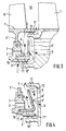
- the deflection plate 6 is designed and arranged in the annular space 4 in such a way that the free peripheral end edge of the part T2, which is approximately vertically unwound from the axial part T1, is spaced substantially below the peripheral end of the web 12 of the wheel disk 3 projecting into the annular space 4 runs.
- the aerodynamically necessary volume in the annular space 4 among other things. in front of or behind the angled part T2, an even more targeted particle centrifugation in the direction of the radially outer wall area of the annular space 4 can be achieved; particle separation can be intensified in the way of the flowing sealing air portion L.
- An optimization of the particle separation in the sense of FIG. 3 can also be generated according to FIG. 4 in that one part T2 of the deflection plate 6 'runs at an angle relative to the axial part T1 and, relative to the axial extent of the swirl nozzles 2; the latter so that the free peripheral end edge of the angled part T2 is aligned with the course of the peripheral end edge of the web 12 of the shut-off seal.
- FIG. 4 embodies an additional alternative of the device, according to which the deflecting plate 6 could be centered and releasably fixed at a step offset from the circumferential slot 16 on the axially projecting web 11 '.
- this alternative design includes the possibility of replacing the obliquely angled deflection plate 6 'by the deflection plate 6 if this should prove to be necessary and useful in the context of certain aerodynamic requirements. 1 and 3, the relevant axial part T1 of the deflection plate 6 is likewise centered and fixed or clamped on a circumferential slot 16 which continues on one side in the axially projecting web 11 '.
Landscapes
- Engineering & Computer Science (AREA)
- Mechanical Engineering (AREA)
- General Engineering & Computer Science (AREA)
- Turbine Rotor Nozzle Sealing (AREA)
- Separating Particles In Gases By Inertia (AREA)
- Structures Of Non-Positive Displacement Pumps (AREA)
Applications Claiming Priority (2)
| Application Number | Priority Date | Filing Date | Title |
|---|---|---|---|
| DE4422965 | 1994-06-30 | ||
| DE4422965A DE4422965A1 (de) | 1994-06-30 | 1994-06-30 | Einrichtung zur Abscheidung von Fremdpartikeln aus der den Laufschaufeln einer Turbine zuzuführenden Kühlluft |
Publications (3)
| Publication Number | Publication Date |
|---|---|
| EP0690202A2 true EP0690202A2 (fr) | 1996-01-03 |
| EP0690202A3 EP0690202A3 (fr) | 1997-10-22 |
| EP0690202B1 EP0690202B1 (fr) | 2001-08-01 |
Family
ID=6521936
Family Applications (1)
| Application Number | Title | Priority Date | Filing Date |
|---|---|---|---|
| EP95109762A Expired - Lifetime EP0690202B1 (fr) | 1994-06-30 | 1995-06-23 | Arrangement pour la séparation des particules de poussière de l'air de refroidissement des aubes de turbine |
Country Status (3)
| Country | Link |
|---|---|
| EP (1) | EP0690202B1 (fr) |
| DE (2) | DE4422965A1 (fr) |
| ES (1) | ES2161803T3 (fr) |
Cited By (19)
| Publication number | Priority date | Publication date | Assignee | Title |
|---|---|---|---|---|
| GB2342124B (en) * | 1998-07-30 | 2003-02-12 | Asea Brown Boveri | Method, device and use of the method for the cooling of guide vanes in a gas turbine plant |
| US6551056B2 (en) | 1999-12-22 | 2003-04-22 | Rolls-Royce Deutschland Ltd & Co Kg | Cooling air ducting system in the high pressure turbine section of a gas turbine engine |
| GB2427657A (en) * | 2005-06-28 | 2007-01-03 | Siemens Ind Turbomachinery Ltd | Cooling arrangement in a device/machine such as a gas turbine engine |
| EP2116692A2 (fr) | 2008-05-07 | 2009-11-11 | Rolls-Royce plc | Agencement d'aube de turbine |
| JP2010501764A (ja) * | 2006-08-22 | 2010-01-21 | シーメンス アクチエンゲゼルシヤフト | ガスタービン |
| EP2378066A3 (fr) * | 2010-04-16 | 2011-12-28 | MTU Aero Engines GmbH | Rotor pour une turbomachine |
| FR2969209A1 (fr) * | 2010-12-21 | 2012-06-22 | Snecma | Etage de turbine pour turbomachine d'aeronef, presentant une etancheite amelioree entre le flasque aval et les aubes de la turbine |
| EP1503046A3 (fr) * | 2003-07-05 | 2012-07-04 | Alstom Technology Ltd | Dispositif de séparation de particules étrangères contenues dans des fluides de refroidissement d'aubes mobiles d'une turbine |
| EP2551453A1 (fr) * | 2011-07-26 | 2013-01-30 | Alstom Technology Ltd | Dispositif de refroidissement d'un compresseur d'un turbomoteur |
| US8851847B2 (en) | 2010-11-15 | 2014-10-07 | Mtu Aero Engines Gmbh | Rotor for a turbo machine |
| US8943791B2 (en) | 2009-09-21 | 2015-02-03 | Rolls-Royce Plc | Dirt particle separator device for use in a gas turbine engine |
| US9988936B2 (en) | 2015-10-15 | 2018-06-05 | General Electric Company | Shroud assembly for a gas turbine engine |
| US10174620B2 (en) | 2015-10-15 | 2019-01-08 | General Electric Company | Turbine blade |
| US10428664B2 (en) | 2015-10-15 | 2019-10-01 | General Electric Company | Nozzle for a gas turbine engine |
| EP2489834B1 (fr) * | 2011-02-18 | 2020-09-16 | General Electric Company | Appareil, procédé et système pour la séparation de particules d'un flux de fluid |
| US10975731B2 (en) | 2014-05-29 | 2021-04-13 | General Electric Company | Turbine engine, components, and methods of cooling same |
| US11033845B2 (en) | 2014-05-29 | 2021-06-15 | General Electric Company | Turbine engine and particle separators therefore |
| CN117145592A (zh) * | 2023-10-31 | 2023-12-01 | 中国航发四川燃气涡轮研究院 | 一种基于异型节流通道的预旋系统及其设计方法 |
| US11918943B2 (en) | 2014-05-29 | 2024-03-05 | General Electric Company | Inducer assembly for a turbine engine |
Families Citing this family (9)
| Publication number | Priority date | Publication date | Assignee | Title |
|---|---|---|---|---|
| EP1041246A1 (fr) * | 1999-03-29 | 2000-10-04 | Siemens Aktiengesellschaft | Aube de turbine à gaz coulée avec refroidissement interne, procédé et dispositif de fabrication d'un collecteur dans l'aube de turbine à gaz |
| DE19960895A1 (de) * | 1999-12-17 | 2001-06-28 | Rolls Royce Deutschland | Mehrstufige Axialturbine einer Turbomaschine |
| DE50208671D1 (de) | 2001-07-13 | 2006-12-21 | Alstom Technology Ltd | Gasturbinenteil mit Kühlluftbohrung |
| US10286407B2 (en) | 2007-11-29 | 2019-05-14 | General Electric Company | Inertial separator |
| US9915176B2 (en) | 2014-05-29 | 2018-03-13 | General Electric Company | Shroud assembly for turbine engine |
| US10167725B2 (en) | 2014-10-31 | 2019-01-01 | General Electric Company | Engine component for a turbine engine |
| US10036319B2 (en) | 2014-10-31 | 2018-07-31 | General Electric Company | Separator assembly for a gas turbine engine |
| US10704425B2 (en) | 2016-07-14 | 2020-07-07 | General Electric Company | Assembly for a gas turbine engine |
| US12241411B1 (en) * | 2023-08-30 | 2025-03-04 | Rtx Corporation | Accessible debris separator for high pressure turbine outside diameter fed static components |
Citations (1)
| Publication number | Priority date | Publication date | Assignee | Title |
|---|---|---|---|---|
| US4173458A (en) | 1977-02-28 | 1979-11-06 | Stiles Arthur G | Air cleaner |
Family Cites Families (14)
| Publication number | Priority date | Publication date | Assignee | Title |
|---|---|---|---|---|
| US3356340A (en) * | 1965-03-15 | 1967-12-05 | Gen Electric | Turbine rotor constructions |
| US3751907A (en) * | 1971-12-08 | 1973-08-14 | Caterpillar Tractor Co | Inertial air cleaner for gas turbine |
| DE2252581A1 (de) * | 1972-10-26 | 1974-05-02 | Kraftwerk Union Ag | Kuehlsystem fuer eine gasturbine |
| CH565942A5 (fr) * | 1973-12-22 | 1975-08-29 | Bbc Brown Boveri & Cie | |
| US4199933A (en) * | 1973-12-22 | 1980-04-29 | Bbc Brown Boveri & Company Limited | Power plant with pressurized-gas generator |
| US3918835A (en) * | 1974-12-19 | 1975-11-11 | United Technologies Corp | Centrifugal cooling air filter |
| DE2941866C2 (de) * | 1978-10-26 | 1982-08-19 | Rolls-Royce Ltd., London | Turbine für ein Gasturbinentriebwerk mit lufgekühlten Turbinenschaufeln |
| US4309147A (en) * | 1979-05-21 | 1982-01-05 | General Electric Company | Foreign particle separator |
| GB2246836B (en) * | 1981-05-07 | 1992-05-13 | Rolls Royce | Fluid flow valve |
| US4798047A (en) * | 1983-12-19 | 1989-01-17 | Elliott Turbomachinery Co., Inc. | Particulate collection and cooling in a turbomachine |
| US4896510A (en) * | 1987-02-06 | 1990-01-30 | General Electric Company | Combustor liner cooling arrangement |
| US4820123A (en) * | 1988-04-25 | 1989-04-11 | United Technologies Corporation | Dirt removal means for air cooled blades |
| DE3835932A1 (de) * | 1988-10-21 | 1990-04-26 | Mtu Muenchen Gmbh | Vorrichtung zur kuehlluftzufuehrung fuer gasturbinen-rotorschaufeln |
| IL96886A (en) * | 1991-01-06 | 1994-08-26 | Israel Aircraft Ind Ltd | Apparatus for separating relatively more dense particulate matter from a relatively less dense fluid flow |
-
1994
- 1994-06-30 DE DE4422965A patent/DE4422965A1/de not_active Withdrawn
-
1995
- 1995-06-23 DE DE59509460T patent/DE59509460D1/de not_active Expired - Lifetime
- 1995-06-23 EP EP95109762A patent/EP0690202B1/fr not_active Expired - Lifetime
- 1995-06-23 ES ES95109762T patent/ES2161803T3/es not_active Expired - Lifetime
Patent Citations (1)
| Publication number | Priority date | Publication date | Assignee | Title |
|---|---|---|---|---|
| US4173458A (en) | 1977-02-28 | 1979-11-06 | Stiles Arthur G | Air cleaner |
Cited By (28)
| Publication number | Priority date | Publication date | Assignee | Title |
|---|---|---|---|---|
| GB2342124B (en) * | 1998-07-30 | 2003-02-12 | Asea Brown Boveri | Method, device and use of the method for the cooling of guide vanes in a gas turbine plant |
| US6551056B2 (en) | 1999-12-22 | 2003-04-22 | Rolls-Royce Deutschland Ltd & Co Kg | Cooling air ducting system in the high pressure turbine section of a gas turbine engine |
| EP1503046A3 (fr) * | 2003-07-05 | 2012-07-04 | Alstom Technology Ltd | Dispositif de séparation de particules étrangères contenues dans des fluides de refroidissement d'aubes mobiles d'une turbine |
| GB2427657A (en) * | 2005-06-28 | 2007-01-03 | Siemens Ind Turbomachinery Ltd | Cooling arrangement in a device/machine such as a gas turbine engine |
| GB2427657B (en) * | 2005-06-28 | 2011-01-19 | Siemens Ind Turbomachinery Ltd | A gas turbine engine |
| JP4896226B2 (ja) * | 2006-08-22 | 2012-03-14 | シーメンス アクチエンゲゼルシヤフト | ガスタービン |
| JP2010501764A (ja) * | 2006-08-22 | 2010-01-21 | シーメンス アクチエンゲゼルシヤフト | ガスタービン |
| EP2116692A2 (fr) | 2008-05-07 | 2009-11-11 | Rolls-Royce plc | Agencement d'aube de turbine |
| EP2116692A3 (fr) * | 2008-05-07 | 2013-07-31 | Rolls-Royce plc | Agencement d'aube de turbine |
| US8943791B2 (en) | 2009-09-21 | 2015-02-03 | Rolls-Royce Plc | Dirt particle separator device for use in a gas turbine engine |
| EP2378066A3 (fr) * | 2010-04-16 | 2011-12-28 | MTU Aero Engines GmbH | Rotor pour une turbomachine |
| US8851847B2 (en) | 2010-11-15 | 2014-10-07 | Mtu Aero Engines Gmbh | Rotor for a turbo machine |
| FR2969209A1 (fr) * | 2010-12-21 | 2012-06-22 | Snecma | Etage de turbine pour turbomachine d'aeronef, presentant une etancheite amelioree entre le flasque aval et les aubes de la turbine |
| EP2489834B1 (fr) * | 2011-02-18 | 2020-09-16 | General Electric Company | Appareil, procédé et système pour la séparation de particules d'un flux de fluid |
| US9382802B2 (en) | 2011-07-26 | 2016-07-05 | General Electric Technology Gmbh | Compressor rotor |
| EP2551453A1 (fr) * | 2011-07-26 | 2013-01-30 | Alstom Technology Ltd | Dispositif de refroidissement d'un compresseur d'un turbomoteur |
| US11033845B2 (en) | 2014-05-29 | 2021-06-15 | General Electric Company | Turbine engine and particle separators therefore |
| US10975731B2 (en) | 2014-05-29 | 2021-04-13 | General Electric Company | Turbine engine, components, and methods of cooling same |
| US11541340B2 (en) | 2014-05-29 | 2023-01-03 | General Electric Company | Inducer assembly for a turbine engine |
| US11918943B2 (en) | 2014-05-29 | 2024-03-05 | General Electric Company | Inducer assembly for a turbine engine |
| US12357933B2 (en) | 2014-05-29 | 2025-07-15 | General Electric Company | Inducer assembly for a turbine engine |
| US10428664B2 (en) | 2015-10-15 | 2019-10-01 | General Electric Company | Nozzle for a gas turbine engine |
| US10174620B2 (en) | 2015-10-15 | 2019-01-08 | General Electric Company | Turbine blade |
| US11021969B2 (en) | 2015-10-15 | 2021-06-01 | General Electric Company | Turbine blade |
| US9988936B2 (en) | 2015-10-15 | 2018-06-05 | General Electric Company | Shroud assembly for a gas turbine engine |
| US11401821B2 (en) | 2015-10-15 | 2022-08-02 | General Electric Company | Turbine blade |
| CN117145592A (zh) * | 2023-10-31 | 2023-12-01 | 中国航发四川燃气涡轮研究院 | 一种基于异型节流通道的预旋系统及其设计方法 |
| CN117145592B (zh) * | 2023-10-31 | 2024-01-09 | 中国航发四川燃气涡轮研究院 | 一种基于异型节流通道的预旋系统及其设计方法 |
Also Published As
| Publication number | Publication date |
|---|---|
| DE59509460D1 (de) | 2001-09-06 |
| EP0690202B1 (fr) | 2001-08-01 |
| ES2161803T3 (es) | 2001-12-16 |
| DE4422965A1 (de) | 1996-01-04 |
| EP0690202A3 (fr) | 1997-10-22 |
Similar Documents
| Publication | Publication Date | Title |
|---|---|---|
| EP0690202A2 (fr) | Arrangement pour la séparation des particules de poussière de l'air de refroidissement des aubes de turbine | |
| EP1659293B1 (fr) | Turbomachine | |
| DE60214137T2 (de) | Verfahren und vorrichtung zur kühlung der schaufelspitzen in einer gasturbine | |
| EP2054586B1 (fr) | Turbine à gaz | |
| DE69605014T2 (de) | Zentrifugalölabscheider für ein Schmierungsgehäuse | |
| EP2499375B1 (fr) | Fond intermédiaire pour une turbomachine radiale | |
| DE4422700A1 (de) | Diffusor für Turbomaschine | |
| DE3302576A1 (de) | Schutzmantel fuer ein fangehaeuse eines axialgasturbinentriebwerks | |
| EP2685054B1 (fr) | Diffuseur d'une turbine de gaz d'échappement | |
| EP0924386A1 (fr) | Méthode et dispositif d'étanchéité pour isoler l'espace entre un rotor et un stator | |
| DE102015120127A1 (de) | Axialverdichterendwandeinrichtung zur steuerung der leckage in dieser | |
| EP2009288A2 (fr) | Turbocompresseur doté d'un séparateur intégré | |
| EP1736635B1 (fr) | Système de transfert d'air entre le compresseur et la turbine d'une turbine à gaz | |
| DE102019110829A1 (de) | Zapfluftentnahmevorrichtung für ein Gasturbinentriebwerk | |
| EP3121371A1 (fr) | Turbine comprenant des aubes directrices refroidies | |
| EP0702129B1 (fr) | Refroidissement du rotor d'une turbine à gaz axiale | |
| DE102015111746A1 (de) | Gekühltes Turbinenlaufrad, insbesondere für ein Flugtriebwerk | |
| EP3034788A2 (fr) | Aube de compresseur d'une turbine a gaz | |
| DE102016124806A1 (de) | Turbinen-Laufschaufelanordnung für eine Gasturbine und Verfahren zum Bereitstellen von Dichtluft in einer Turbinen-Laufschaufelanordnung | |
| EP2808492B1 (fr) | Palier de turbine doté d'un système de purge et procédé de purge d'un flux de gaz d'arrêt | |
| EP3109410A1 (fr) | Dispositif de stator pour une turbomachine comprenant un dispositif de carter et plusieurs aubes directrices | |
| EP1260677A2 (fr) | Turbine axiale avec protection contre des éclatements | |
| CH701151B1 (de) | Turbomaschine mit einem Verdichterradelement. | |
| DE202022104248U1 (de) | Aufladevorrichtung mit Axiallager | |
| EP2730744B1 (fr) | Turbosoufflante de gaz d'échappement |
Legal Events
| Date | Code | Title | Description |
|---|---|---|---|
| PUAI | Public reference made under article 153(3) epc to a published international application that has entered the european phase |
Free format text: ORIGINAL CODE: 0009012 |
|
| AK | Designated contracting states |
Kind code of ref document: A2 Designated state(s): DE ES FR GB IT |
|
| PUAL | Search report despatched |
Free format text: ORIGINAL CODE: 0009013 |
|
| AK | Designated contracting states |
Kind code of ref document: A3 Designated state(s): DE ES FR GB IT |
|
| 17P | Request for examination filed |
Effective date: 19980422 |
|
| 17Q | First examination report despatched |
Effective date: 20000113 |
|
| GRAG | Despatch of communication of intention to grant |
Free format text: ORIGINAL CODE: EPIDOS AGRA |
|
| GRAG | Despatch of communication of intention to grant |
Free format text: ORIGINAL CODE: EPIDOS AGRA |
|
| GRAH | Despatch of communication of intention to grant a patent |
Free format text: ORIGINAL CODE: EPIDOS IGRA |
|
| GRAH | Despatch of communication of intention to grant a patent |
Free format text: ORIGINAL CODE: EPIDOS IGRA |
|
| RAP1 | Party data changed (applicant data changed or rights of an application transferred) |
Owner name: MTU AERO ENGINES GMBH |
|
| GRAA | (expected) grant |
Free format text: ORIGINAL CODE: 0009210 |
|
| ITF | It: translation for a ep patent filed | ||
| AK | Designated contracting states |
Kind code of ref document: B1 Designated state(s): DE ES FR GB IT |
|
| REF | Corresponds to: |
Ref document number: 59509460 Country of ref document: DE Date of ref document: 20010906 |
|
| GBT | Gb: translation of ep patent filed (gb section 77(6)(a)/1977) |
Effective date: 20010914 |
|
| ET | Fr: translation filed | ||
| REG | Reference to a national code |
Ref country code: ES Ref legal event code: FG2A Ref document number: 2161803 Country of ref document: ES Kind code of ref document: T3 |
|
| REG | Reference to a national code |
Ref country code: GB Ref legal event code: IF02 |
|
| PLBE | No opposition filed within time limit |
Free format text: ORIGINAL CODE: 0009261 |
|
| STAA | Information on the status of an ep patent application or granted ep patent |
Free format text: STATUS: NO OPPOSITION FILED WITHIN TIME LIMIT |
|
| 26N | No opposition filed | ||
| PGFP | Annual fee paid to national office [announced via postgrant information from national office to epo] |
Ref country code: FR Payment date: 20100706 Year of fee payment: 16 Ref country code: ES Payment date: 20100625 Year of fee payment: 16 |
|
| PGFP | Annual fee paid to national office [announced via postgrant information from national office to epo] |
Ref country code: IT Payment date: 20100621 Year of fee payment: 16 |
|
| PGFP | Annual fee paid to national office [announced via postgrant information from national office to epo] |
Ref country code: GB Payment date: 20100618 Year of fee payment: 16 Ref country code: DE Payment date: 20100625 Year of fee payment: 16 |
|
| GBPC | Gb: european patent ceased through non-payment of renewal fee |
Effective date: 20110623 |
|
| PG25 | Lapsed in a contracting state [announced via postgrant information from national office to epo] |
Ref country code: IT Free format text: LAPSE BECAUSE OF NON-PAYMENT OF DUE FEES Effective date: 20110623 |
|
| REG | Reference to a national code |
Ref country code: FR Ref legal event code: ST Effective date: 20120229 |
|
| REG | Reference to a national code |
Ref country code: DE Ref legal event code: R119 Ref document number: 59509460 Country of ref document: DE Effective date: 20120103 |
|
| PG25 | Lapsed in a contracting state [announced via postgrant information from national office to epo] |
Ref country code: FR Free format text: LAPSE BECAUSE OF NON-PAYMENT OF DUE FEES Effective date: 20110630 Ref country code: DE Free format text: LAPSE BECAUSE OF NON-PAYMENT OF DUE FEES Effective date: 20120103 |
|
| PG25 | Lapsed in a contracting state [announced via postgrant information from national office to epo] |
Ref country code: GB Free format text: LAPSE BECAUSE OF NON-PAYMENT OF DUE FEES Effective date: 20110623 |
|
| REG | Reference to a national code |
Ref country code: ES Ref legal event code: FD2A Effective date: 20121116 |
|
| PG25 | Lapsed in a contracting state [announced via postgrant information from national office to epo] |
Ref country code: ES Free format text: LAPSE BECAUSE OF NON-PAYMENT OF DUE FEES Effective date: 20110624 |