EP0690228A1 - Manchette de montage et poutre de flexion pour pale aérodynamique - Google Patents
Manchette de montage et poutre de flexion pour pale aérodynamique Download PDFInfo
- Publication number
- EP0690228A1 EP0690228A1 EP95109984A EP95109984A EP0690228A1 EP 0690228 A1 EP0690228 A1 EP 0690228A1 EP 95109984 A EP95109984 A EP 95109984A EP 95109984 A EP95109984 A EP 95109984A EP 0690228 A1 EP0690228 A1 EP 0690228A1
- Authority
- EP
- European Patent Office
- Prior art keywords
- mounting
- propeller blade
- propeller
- bending
- axis
- Prior art date
- Legal status (The legal status is an assumption and is not a legal conclusion. Google has not performed a legal analysis and makes no representation as to the accuracy of the status listed.)
- Granted
Links
- 238000005452 bending Methods 0.000 title claims description 58
- 239000004033 plastic Substances 0.000 claims abstract description 13
- 229920003023 plastic Polymers 0.000 claims abstract description 13
- 239000000835 fiber Substances 0.000 claims description 54
- 238000004804 winding Methods 0.000 claims description 38
- 238000000034 method Methods 0.000 claims description 16
- 125000006850 spacer group Chemical group 0.000 claims description 16
- 239000000463 material Substances 0.000 claims description 14
- 238000004519 manufacturing process Methods 0.000 claims description 12
- 239000004744 fabric Substances 0.000 claims description 8
- 238000004026 adhesive bonding Methods 0.000 claims description 3
- 239000002657 fibrous material Substances 0.000 claims description 2
- 239000004745 nonwoven fabric Substances 0.000 claims 1
- 230000008569 process Effects 0.000 description 8
- 230000007704 transition Effects 0.000 description 5
- 230000005540 biological transmission Effects 0.000 description 4
- 239000000057 synthetic resin Substances 0.000 description 4
- 229920003002 synthetic resin Polymers 0.000 description 4
- 230000004048 modification Effects 0.000 description 2
- 238000012986 modification Methods 0.000 description 2
- OKTJSMMVPCPJKN-UHFFFAOYSA-N Carbon Chemical compound [C] OKTJSMMVPCPJKN-UHFFFAOYSA-N 0.000 description 1
- 229920000049 Carbon (fiber) Polymers 0.000 description 1
- 229920002430 Fibre-reinforced plastic Polymers 0.000 description 1
- 239000004952 Polyamide Substances 0.000 description 1
- 229910000831 Steel Inorganic materials 0.000 description 1
- 239000000853 adhesive Substances 0.000 description 1
- 230000001070 adhesive effect Effects 0.000 description 1
- 239000004760 aramid Substances 0.000 description 1
- 229920003235 aromatic polyamide Polymers 0.000 description 1
- 230000015572 biosynthetic process Effects 0.000 description 1
- 229910052799 carbon Inorganic materials 0.000 description 1
- 239000004917 carbon fiber Substances 0.000 description 1
- 230000008859 change Effects 0.000 description 1
- 238000010276 construction Methods 0.000 description 1
- 230000003247 decreasing effect Effects 0.000 description 1
- 230000007547 defect Effects 0.000 description 1
- 238000011161 development Methods 0.000 description 1
- 230000018109 developmental process Effects 0.000 description 1
- 238000006073 displacement reaction Methods 0.000 description 1
- 239000011151 fibre-reinforced plastic Substances 0.000 description 1
- 239000011521 glass Substances 0.000 description 1
- 239000003365 glass fiber Substances 0.000 description 1
- 239000003292 glue Substances 0.000 description 1
- 238000010030 laminating Methods 0.000 description 1
- VNWKTOKETHGBQD-UHFFFAOYSA-N methane Chemical compound C VNWKTOKETHGBQD-UHFFFAOYSA-N 0.000 description 1
- 239000000203 mixture Substances 0.000 description 1
- 238000005457 optimization Methods 0.000 description 1
- 229920002647 polyamide Polymers 0.000 description 1
- 239000004848 polyfunctional curative Substances 0.000 description 1
- 238000000275 quality assurance Methods 0.000 description 1
- 238000003908 quality control method Methods 0.000 description 1
- 230000002787 reinforcement Effects 0.000 description 1
- 239000011343 solid material Substances 0.000 description 1
- 238000005507 spraying Methods 0.000 description 1
- 239000010959 steel Substances 0.000 description 1
Images


Classifications
-
- F—MECHANICAL ENGINEERING; LIGHTING; HEATING; WEAPONS; BLASTING
- F03—MACHINES OR ENGINES FOR LIQUIDS; WIND, SPRING, OR WEIGHT MOTORS; PRODUCING MECHANICAL POWER OR A REACTIVE PROPULSIVE THRUST, NOT OTHERWISE PROVIDED FOR
- F03D—WIND MOTORS
- F03D1/00—Wind motors with rotation axis substantially parallel to the air flow entering the rotor
- F03D1/06—Rotors
- F03D1/065—Rotors characterised by their construction elements
- F03D1/0658—Arrangements for fixing wind-engaging parts to a hub
-
- Y—GENERAL TAGGING OF NEW TECHNOLOGICAL DEVELOPMENTS; GENERAL TAGGING OF CROSS-SECTIONAL TECHNOLOGIES SPANNING OVER SEVERAL SECTIONS OF THE IPC; TECHNICAL SUBJECTS COVERED BY FORMER USPC CROSS-REFERENCE ART COLLECTIONS [XRACs] AND DIGESTS
- Y02—TECHNOLOGIES OR APPLICATIONS FOR MITIGATION OR ADAPTATION AGAINST CLIMATE CHANGE
- Y02E—REDUCTION OF GREENHOUSE GAS [GHG] EMISSIONS, RELATED TO ENERGY GENERATION, TRANSMISSION OR DISTRIBUTION
- Y02E10/00—Energy generation through renewable energy sources
- Y02E10/70—Wind energy
- Y02E10/72—Wind turbines with rotation axis in wind direction
Definitions
- the invention relates to a propeller blade made of plastic material, with a mounting and bending beam which extends from the end region near the axis of rotation and into the propeller blade, which is fixed to the two opposite inner surfaces of the propeller blade consisting of two interconnected half-shells, and with two on the opposite inner surfaces the two half-shells fixed and extending as an extension of the mounting and bending beam essentially over the length of the propeller wing stiffening belts and a method for producing this propeller wing.
- Such propeller blades can be, for example, blades of an aircraft propeller, a propeller, a turbine or a propeller of a wind turbine.
- the known propeller blades made of plastic material are used in the so-called hand-laying process manufactured, that is, fiber mats impregnated with synthetic resin are placed on top of each other in layers.
- processes with wet laminates or pre-impregnated fabrics or unidirectional fibers are also known, which can also be deposited by machine.
- the two half-shells are manufactured separately from one another, and the mounting and bending beam and the two stiffening belts connected to one another are molded into one of the half-shells using the same manufacturing technique.
- Another disadvantage of the known method is that one of the various elements is produced incorrectly or areas of the propeller blade, e.g. B. by an incorrect mixture of the plastic material, by forgetting or incorrect dosage of the hardener u. Like., The entire propeller blade is unusable and can no longer be used as a whole. This can often lead to an expensive reject, even with relatively small errors, taking into account the lost time in particular.
- An object of the present invention is to improve a propeller blade of the type mentioned above made of plastic material so that it can be manufactured more easily, more safely and more cost-effectively, with the quality of the individual blade components also reducing the risk of the entire propeller blade being completely unusable in the event of faults becomes.
- This object is achieved in that the mounting and bending beam and the stiffening belts are fixed as prefabricated elements in the half-shells of the propeller blade.
- the mounting and bending beam and the stiffening belts Due to the separate production of the mounting and bending beam and the stiffening belts, these can be produced quickly and efficiently, for example by machine means, with the mounting and Bending beam as a one-piece component can be better optimized in terms of its mechanical properties.
- the assembly can then be carried out relatively quickly, so that the propeller wing can be manufactured faster and overall less expensive. In the event of a defect in one of the elements, this can be discarded as a whole without affecting the propeller wing, so that a possible scrap is less expensive. Shorter cycle times due to lower tool occupancy and improved quality control and quality assurance are further advantages.
- the prefabricated elements are expediently glued into the half-shells, these two half-shells themselves being glued to one another and thus to the prefabricated elements. In addition to quick assembly, this also ensures good strength.
- the mounting and bending beam overlaps with the stiffening belts in order to achieve good power transmission and good strength.
- the areas of overlap show to achieve continuous power transmission a decreasing thickness and are in particular wedge-shaped or busied.
- the mounting and bending beam is glued to the stiffening belts at the overlap areas, especially with its top and bottom.
- At least one prefabricated spacer element (transverse force web) is provided between the stiffening belts in order to fix the distance between the two half-shells of the propeller wing and in particular to increase the rigidity.
- the prefabricated spacer element also contributes to more efficient production and is preferably glued between the stiffening belts.
- the stiffening belts and the at least one spacer element can together form a prefabricated element.
- the plastic material is fiber-reinforced to increase strength.
- fibers or fiber mats with different properties and fiber directions can also be used in the various areas.
- the mounting and bending beam is at the end area near the rotary axis essentially tubular to achieve easy assembly and good power transmission.
- this mounting and bending beam consists of wound, resin-impregnated fiber layers, the fiber direction in the area close to the axis of rotation with regard to good torsional and bending strength and in the opposite Range is optimized with a view to good bending and shear strength.
- the fibers in the region close to the axis of rotation run essentially in the longitudinal direction and in intersecting oblique directions and in the opposite region on the top and bottom sides essentially in the longitudinal direction and on the other sides essentially at an angle of 45 ° to the longitudinal direction with crossed winding.
- the top and bottom are connected to the stiffening belts, which also have fibers running in the longitudinal direction, in order to be able to transmit the corresponding forces.
- An advantageous method for producing such a propeller wing made of plastic material is that in the first half-shell of the propeller wing prefabricated in a mold, the prefabricated elements, namely the mounting and bending beams and the two stiffening belts, are fixed with the spacing element arranged between them, and then the prefabricated second half shell is fixed to the first half shell, the mounting and bending beam and the corresponding stiffening belt. Fixing is done by gluing.
- a layer process using synthetic resin-impregnated fiber mats is suitable for producing the two half-shells.
- a shaped winding body with a synthetic resin-impregnated fiber material (e.g. a fiber strand, a unidirectional tape or fabric or a fabric or scrim with fibers of different directions) so that the fibers in the area close to the axis of rotation run essentially in the longitudinal direction and in intersecting oblique directions and run in the opposite region on the top and bottom essentially in the longitudinal direction and crossed on the other sides, for example at an angle of essentially 45 ° to the longitudinal direction.
- a synthetic resin-impregnated fiber material e.g. a fiber strand, a unidirectional tape or fabric or a fabric or scrim with fibers of different directions
- the shaped winding body is preferably provided with winding pins to facilitate the winding process, in which case a fiber strand impregnated with synthetic resin is then wound onto the shaped winding body and around the winding pins. After winding, the winding pins and then the shaped winding body are removed if necessary.
- the plan view shown in FIG. 1 shows a propeller blade in the semi-finished state during the manufacturing process, in which the free end area removed from the axis of rotation during operation is cut off to shorten the drawing.
- Such propeller blades are used for aircraft propellers, propellers, turbine wheels and wind power propellers.
- the exemplary embodiment shown relates to the propeller blade of a rotor for wind power machines, such a propeller blade being 30 m long, for example.
- two half-shells 10, 11, which determine the outer contour of the propeller blade are first produced in corresponding shapes.
- synthetic resin-impregnated fiber mats such as glass fiber mats or carbon fiber mats
- the half-shells 10, 11 can also be produced in a spraying process, fiber reinforcement also taking place here.
- Different fiber mats can also be used, for example areas with higher stress can be provided with higher quality fiber mats and less stressed areas with cheaper fiber mats.
- Fibers are available, for example, glass, carbon, aramid and polyamide fibers.
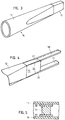
- an assembly and bending beam 12 is produced, as shown in FIG. 3 in the finished state.
- a corresponding shaped winding body 13 according to FIG. 2 is provided with limits of winding pins 24, for example with small steel pins.
- the winding takes place with a fiber strand, which is unwound by machine from a supply winding body, not shown.
- This fiber strand is impregnated with synthetic resin and then wound onto the shaped winding body 13 with the aid of the winding pins 24.
- the fiber strand is moved with a winding arm (not shown), the shaped winding body 13 also being movably clamped.
- the winding is carried out in such a way that the mounting area 14 of the mounting and bending beam 12 near the axis of rotation, with the aid of which the finished propeller wing is mounted on an axis of rotation, is designed for optimum torsional and bending strength.
- the fibers run there both in the longitudinal direction and at an angle at different angles when the fibers intersect.
- the winding takes place essentially with a view to good bending and Shear resistance.
- the fibers run essentially in the longitudinal direction, since these areas - as will be explained in more detail later - are connected to stiffening belts 17, 18, the fibers of which also run in the longitudinal direction.
- the fibers run essentially crossed on both sides at an angle of, for example, 45 °.
- the fiber directions gradually merge into one another in order to achieve continuous transitions between the different load zones. These transitions can also be achieved by wrapping the winding pins appropriately.
- This fiber covering can also be done by unidirectional tapes or fabrics as well as fabrics or scrims with fibers in the longitudinal and transverse directions or other suitable fiber directions.
- FIG. 2 the wound plastic impregnated fiber 16 is shown with its different fiber directions in the individual areas by corresponding lines.
- the shaped winding body 13 and thus also the resulting assembly and bending beam 12 are tubular in the assembly area 14 near the axis of rotation with an annular cross-section and has in Area 15 remote from the axis of rotation has a rectangular cross section, the transition taking place continuously.
- the tubular area can have different cross-sectional shapes, for example round, oval, angular or the like.
- winding pins 24 and then the shaped winding body 13 are removed, so that the assembly and bending body 12 according to FIG. 3 is then present.
- the assembly area 14 near the axis of rotation is cut to length as required.
- Other winding aids can also take the place of winding pins 24.
- Two elongated, slat-shaped stiffening straps 17, 18 are made separately from fiber-reinforced plastic material.
- the fibers run essentially in the longitudinal direction.
- a bar-shaped spacer 19 (transverse force web) made of plastic material, which defines the distance between the two stiffening straps 17, 18.
- this spacer element 19 can consist of a lighter solid material, or it can be designed as a hollow body, or it can also be made of fiber-reinforced material with load-appropriate fiber angles or from a combination of these possibilities exist.
- a stiffening belt 17 is first arranged and glued to the inside of the half-shell 10 in the longitudinal direction according to FIG. 1. Then the assembly and bending body 12 is inserted and also glued to the stiffening belt 17 and the half-shell 10.
- the mounting and bending body 12 protrudes with its mounting area 14 near the axis of rotation beyond the half-shell 10, which of course does not always have to be the case.
- the area of overlap between the stiffening belt 17 and the mounting and bending body 12 is enlarged in FIG. 4 and shown in perspective.
- the stiffening belts 17, 18 have wedge-shaped end regions 20, 21, the angle of which is adapted to corresponding bevels 22 on the region 15 of the mounting and bending beam 12 remote from the axis of rotation, so that busy stepless transitions occur and the power transmission is thereby made possible.
- the spacer 19 and the upper stiffening belt 18 are glued in accordance with FIGS. 4 and 5, respectively.
- the prefabricated second half-shell 11 is placed over it, and it lies against the stiffening belt 18 and can be glued to it.
- the outer edges of the half-shells 10, 11 are glued together.
- the mounting area 14 of the mounting and bending beam 12 near the axis of rotation is also provided with the corresponding mounting holes 23, which are only indicated schematically in FIG. 1.
- the mounting holes 23 can of course also be predetermined, so that the mounting and bending beam 12 can be glued in position with fixing devices in the half-shell 10.
- the stiffening straps 17, 18 can be produced together with the spacer 19 as a prefabricated unit, also previously connected to the mounting and bending beam 12 and glued as a whole to the half-shell 10 or half-shell 11, or the stiffening straps 17, 18 are first glued separately to the two half-shells 10, 11 and only connected to one another via the spacer element when the half-shells are glued.
- the adhesive connections described can alternatively or additionally also be designed as screw connections or connected to one another in another known manner.
- the connected elements can be reinforced by overlapping resin-impregnated mat elements.
- the stiffening belts 17, 18 can also extend as far as the end region of the mounting and bending beam 12 close to the axis of rotation, that is to say they can overlap them practically completely. This eliminates the need for wedge-shaped end areas and corresponding bevels for the formation of busy stepless transitions.
- Such stiffening belts widen along the mounting and bending beam towards the end of the axis of rotation so that they practically encircle them in the manner of half shells, the thickness of the stiffening belts also being able to decrease continuously.
- Stiffening belts designed in this way which can have predominantly lengthways, synthetic resin-impregnated fibers, are inserted into the half-shells either as prefabricated, hardened parts or, if separate manufacture and testing is omitted, in the form of still damp, non-hardened bands or fiber ropes (so-called roving strands), whereby due to the still moist, uncured state, an adjustment and displacement of the mounting and bending beam takes place automatically in at least one half-shell.
- Such prefabricated fiber ropes consist of a large number of resin-impregnated strands running alongside one another, so-called rovings.
- the spacer elements or a corresponding web can then be placed on the stiffening belts, which are still in the uncured state in the half-shells or are placed on, whereby due to the still uncured state, automatic gluing takes place here again at least in a half-shell.
- the stiffening of the mounting and bending beam due to the virtually completely overlapping stiffening straps can lead to a change in the fiber directions of the mounting and bending beam to be provided, that is to say, the stiffening by the stiffening belts is also taken into account in the conception of the winding process of this mounting and bending beam.
Landscapes
- Engineering & Computer Science (AREA)
- Life Sciences & Earth Sciences (AREA)
- Sustainable Development (AREA)
- Sustainable Energy (AREA)
- Chemical & Material Sciences (AREA)
- Combustion & Propulsion (AREA)
- Mechanical Engineering (AREA)
- General Engineering & Computer Science (AREA)
- Moulding By Coating Moulds (AREA)
Applications Claiming Priority (2)
| Application Number | Priority Date | Filing Date | Title |
|---|---|---|---|
| DE4423115A DE4423115A1 (de) | 1994-07-01 | 1994-07-01 | Propellerflügel aus Kunststoffmaterial und Verfahren zu seiner Herstellung |
| DE4423115 | 1994-07-01 |
Publications (2)
| Publication Number | Publication Date |
|---|---|
| EP0690228A1 true EP0690228A1 (fr) | 1996-01-03 |
| EP0690228B1 EP0690228B1 (fr) | 2000-11-22 |
Family
ID=6522024
Family Applications (1)
| Application Number | Title | Priority Date | Filing Date |
|---|---|---|---|
| EP95109984A Expired - Lifetime EP0690228B1 (fr) | 1994-07-01 | 1995-06-27 | Manchette de montage et poutre de flexion pour pale aérodynamique |
Country Status (3)
| Country | Link |
|---|---|
| EP (1) | EP0690228B1 (fr) |
| DE (2) | DE4423115A1 (fr) |
| DK (1) | DK0690228T3 (fr) |
Cited By (7)
| Publication number | Priority date | Publication date | Assignee | Title |
|---|---|---|---|---|
| DE19741495A1 (de) * | 1997-09-19 | 1999-03-25 | Egon Gelhard | Windkraftvorrichtung mit Darrieus-H-Rotor |
| WO2002006667A1 (fr) * | 2000-07-19 | 2002-01-24 | Aloys Wobben | Moyeu de pale |
| DE19833869C5 (de) * | 1998-07-22 | 2004-07-01 | EUROS Entwicklungsgesellschaft für Windkraftanlagen | Vorrichtung zur Herstellung von Rotorblättern |
| WO2006039953A1 (fr) * | 2004-10-08 | 2006-04-20 | Eew Maschinenbau Gmbh | Pale de rotor d'une centrale eolienne |
| WO2010049561A1 (fr) * | 2008-10-28 | 2010-05-06 | Gamesa Innovation & Technology, S.L. | Pale d'aérogénérateur à panneaux multiples avec emplanture intégrée |
| US8898901B2 (en) | 2010-03-22 | 2014-12-02 | Vestas Wind Systems A/S | Method for manufacturing a blade spar for a wind turbine |
| DE102004057979C5 (de) * | 2004-11-30 | 2019-09-26 | Senvion Gmbh | Rotorblatt |
Families Citing this family (4)
| Publication number | Priority date | Publication date | Assignee | Title |
|---|---|---|---|---|
| DE19856305A1 (de) * | 1998-12-07 | 2000-06-08 | Dirk Buechler | Schiffsantrieb |
| DE10336461A1 (de) * | 2003-08-05 | 2005-03-03 | Aloys Wobben | Verfahren zur Herstellung eines Rotorblattes einer Windenergieanlage |
| US7976282B2 (en) | 2007-01-26 | 2011-07-12 | General Electric Company | Preform spar cap for a wind turbine rotor blade |
| US8250761B2 (en) * | 2010-12-13 | 2012-08-28 | General Electric Company | Methods of manufacturing rotor blades for a wind turbine |
Citations (7)
| Publication number | Priority date | Publication date | Assignee | Title |
|---|---|---|---|---|
| FR1216378A (fr) * | 1958-11-17 | 1960-04-25 | Propellerbau Ges Haw & Co Deut | Pales d'hélice |
| US4339230A (en) * | 1980-04-22 | 1982-07-13 | Hercules Incorporated | Bifoil blade |
| FR2518979A1 (fr) * | 1981-12-28 | 1983-07-01 | United Technologies Corp | Procede de fabrication d'articles enroules de filaments |
| JPS61192864A (ja) * | 1985-02-20 | 1986-08-27 | Yamaha Motor Co Ltd | 風車のロ−タブレ−ド構造 |
| US4728263A (en) * | 1986-08-25 | 1988-03-01 | Basso Robert J | Wind turbine blade construction |
| EP0258926A1 (fr) * | 1986-08-18 | 1988-03-09 | Strijense Kunststof Technieken B.V. | Rotor d'éolienne bipale |
| JPH05269868A (ja) * | 1992-03-25 | 1993-10-19 | Sumitomo Metal Ind Ltd | 孔明き中空複合材料の製造方法 |
Family Cites Families (15)
| Publication number | Priority date | Publication date | Assignee | Title |
|---|---|---|---|---|
| DE1264266B (de) * | 1963-03-29 | 1968-03-21 | Boelkow Gmbh | Verfahren zum Herstellen von Rotorblaettern aus glasfaserverstaerktem Kunststoff |
| DE2035541A1 (en) * | 1970-07-17 | 1972-01-20 | Dynamit Nobel Ag | Vessel cladding - using studs as anchor points to give winding angle for even coverage in rocket motor systems |
| US3799701A (en) * | 1972-02-28 | 1974-03-26 | United Aircraft Corp | Composite fan blade and method of construction |
| DD103200A1 (fr) * | 1973-04-11 | 1974-01-12 | ||
| MC1123A1 (fr) * | 1976-07-20 | 1977-08-12 | G Grandclement | Electrovanne |
| DE2746290A1 (de) * | 1977-10-14 | 1979-04-19 | Maschf Augsburg Nuernberg Ag | Verfahren zur wicklung von faserverstaerkten verbundkoerpern |
| IT7967327A0 (it) * | 1979-02-15 | 1979-02-15 | Fiat Ricerche | Pala per motori eolici |
| BR8105757A (pt) * | 1980-10-02 | 1982-05-25 | United Technologies Corp | Processo pra a producao de um aerofolio |
| DE3114567A1 (de) * | 1981-04-10 | 1982-10-28 | Messerschmitt-Bölkow-Blohm GmbH, 8000 München | "grossflaechiges rotorblatt" |
| DE3418691A1 (de) * | 1984-05-19 | 1986-02-06 | Messerschmitt-Bölkow-Blohm GmbH, 8012 Ottobrunn | Hohlkoerper aus duennem blech sowie verfahren und vorrichtung zu dessen herstellung durch blasumformen |
| US4621980A (en) * | 1984-09-19 | 1986-11-11 | United Technologies Corporation | Fiber reinforced composite spar for a rotary wing aircraft |
| DE3602293A1 (de) * | 1986-01-25 | 1987-08-06 | Audi Ag | Verbindung von zwei einen hohlraum einschliessenden kunststoffteilen durch klebung, insbesondere klappe fuer eine kraftfahrzeugkarosserie |
| SE8600369D0 (sv) * | 1986-01-28 | 1986-01-28 | Stromberg Karl Otto | Propeller jemte sett att framstella en sadan |
| IL102867A (en) * | 1991-08-28 | 1998-02-08 | United Technologies Corp | Bearingless main motor assembly torque tube and method for fabricating same |
| DK179891D0 (da) * | 1991-10-30 | 1991-10-30 | Gori 1902 As | Elastomerpropel med fleksibel bladkaerne |
-
1994
- 1994-07-01 DE DE4423115A patent/DE4423115A1/de not_active Withdrawn
-
1995
- 1995-06-27 DE DE59508869T patent/DE59508869D1/de not_active Expired - Fee Related
- 1995-06-27 EP EP95109984A patent/EP0690228B1/fr not_active Expired - Lifetime
- 1995-06-27 DK DK95109984T patent/DK0690228T3/da active
Patent Citations (7)
| Publication number | Priority date | Publication date | Assignee | Title |
|---|---|---|---|---|
| FR1216378A (fr) * | 1958-11-17 | 1960-04-25 | Propellerbau Ges Haw & Co Deut | Pales d'hélice |
| US4339230A (en) * | 1980-04-22 | 1982-07-13 | Hercules Incorporated | Bifoil blade |
| FR2518979A1 (fr) * | 1981-12-28 | 1983-07-01 | United Technologies Corp | Procede de fabrication d'articles enroules de filaments |
| JPS61192864A (ja) * | 1985-02-20 | 1986-08-27 | Yamaha Motor Co Ltd | 風車のロ−タブレ−ド構造 |
| EP0258926A1 (fr) * | 1986-08-18 | 1988-03-09 | Strijense Kunststof Technieken B.V. | Rotor d'éolienne bipale |
| US4728263A (en) * | 1986-08-25 | 1988-03-01 | Basso Robert J | Wind turbine blade construction |
| JPH05269868A (ja) * | 1992-03-25 | 1993-10-19 | Sumitomo Metal Ind Ltd | 孔明き中空複合材料の製造方法 |
Non-Patent Citations (2)
| Title |
|---|
| PATENT ABSTRACTS OF JAPAN vol. 011, no. 016 (M - 554) 16 January 1987 (1987-01-16) * |
| PATENT ABSTRACTS OF JAPAN vol. 018, no. 037 (M - 1545) 20 January 1994 (1994-01-20) * |
Cited By (9)
| Publication number | Priority date | Publication date | Assignee | Title |
|---|---|---|---|---|
| DE19741495A1 (de) * | 1997-09-19 | 1999-03-25 | Egon Gelhard | Windkraftvorrichtung mit Darrieus-H-Rotor |
| DE19833869C5 (de) * | 1998-07-22 | 2004-07-01 | EUROS Entwicklungsgesellschaft für Windkraftanlagen | Vorrichtung zur Herstellung von Rotorblättern |
| WO2002006667A1 (fr) * | 2000-07-19 | 2002-01-24 | Aloys Wobben | Moyeu de pale |
| WO2006039953A1 (fr) * | 2004-10-08 | 2006-04-20 | Eew Maschinenbau Gmbh | Pale de rotor d'une centrale eolienne |
| DE102004057979C5 (de) * | 2004-11-30 | 2019-09-26 | Senvion Gmbh | Rotorblatt |
| WO2010049561A1 (fr) * | 2008-10-28 | 2010-05-06 | Gamesa Innovation & Technology, S.L. | Pale d'aérogénérateur à panneaux multiples avec emplanture intégrée |
| ES2341074A1 (es) * | 2008-10-28 | 2010-06-14 | GAMESA INNOVATION & TECHNOLOGY, S.L | Una pala de aerogenerador multi-panel con la raiz integrada. |
| ES2341074B1 (es) * | 2008-10-28 | 2011-05-20 | GAMESA INNOVATION & TECHNOLOGY, S.L | Una pala de aerogenerador multi-panel con la raiz integrada. |
| US8898901B2 (en) | 2010-03-22 | 2014-12-02 | Vestas Wind Systems A/S | Method for manufacturing a blade spar for a wind turbine |
Also Published As
| Publication number | Publication date |
|---|---|
| DE4423115A1 (de) | 1996-01-04 |
| EP0690228B1 (fr) | 2000-11-22 |
| DK0690228T3 (da) | 2001-03-26 |
| DE59508869D1 (de) | 2000-12-28 |
Similar Documents
| Publication | Publication Date | Title |
|---|---|---|
| DE19613090B4 (de) | Träger für ein Luftschiff | |
| DE102005059933B4 (de) | Flechttechnisch hergestelltes Faserverbundbauteil | |
| DE2611235C2 (de) | Rotorblatt für Drehflügler, insbesondere Hubschrauber | |
| EP0657646B1 (fr) | Pale de rotor pour éolienne | |
| EP2082903B1 (fr) | Ressort de véhicule en matière active à fibres composites | |
| DE69100380T2 (de) | Struktur und Verfahren zur Herstellung eines Flugzeugrumpfs. | |
| EP2046564B1 (fr) | Procédé de production de plusieurs éléments composites à base de fibres | |
| DE102012210043A1 (de) | Verfahren und Vorrichtung zur Herstellung einer Leichtbaustruktur sowie Leichtbaustruktur | |
| DE2757965A1 (de) | Schubuebertragungselement und verfahren zu dessen herstellung | |
| EP1985465A1 (fr) | Rayon, roue et procédé de fabrication d'un rayon, en particulier pour vélos | |
| DE2545929C2 (de) | AnscMuBelement zur Einleitung von Kräften in ein Bauteil | |
| EP0690228B1 (fr) | Manchette de montage et poutre de flexion pour pale aérodynamique | |
| DE10326422A1 (de) | Verfahren zur Herstellung von sich in einer Längsrichtung erstreckenden FVK-Hohlprofilen | |
| WO2009112017A2 (fr) | Procédé de fabrication d'une pale de rotor pour une installation éolienne et pale de rotor fabriquée selon ce procédé | |
| EP3723963B1 (fr) | Procédé de fabrication d'un composant et composant | |
| DE102004028707A1 (de) | Gerüstsystem, zur Verwendung im Karosseriebau der Kfz-Industrie, und Verfahren zum Herstellen von Teilen eines derartigen Gerüstsystems | |
| EP3793793B1 (fr) | Procédé de fabrication d'un profilé creux présentant des courbures et des sections transversales variables | |
| DE1923888B2 (de) | Verfahren zur Herstellung einer Verdichterschaufel aus faserverstärktem Material | |
| EP3490782B1 (fr) | Procédé pour la fabrication d'une pièce composite à fibres multicouche, tridimensionnelle | |
| EP2607058A1 (fr) | Élément structurel à symétrie de rotation dans la construction de grilles et son procédé de fabrication | |
| DE102017128496B4 (de) | Verfahren zum Herstellen eines Strukturabschnitts eines Fahrzeugs | |
| DE102010023669B4 (de) | Endlosfaser-Verbundbauteile, sowie Verfahren zur Herstellung für Endlosfaser-Verbundbauteile | |
| DE102007025556B4 (de) | Verfahren zur Herstellung von Bauelementen aus Faser verstärkten Kunststoffen | |
| DE102020000603A1 (de) | Wickelwerkzeug zur Herstellung von endlosfaserverstärkten Polymer-Formteilen und Verfahren zu deren Herstellung mittels eines solchen Wickelwerkzeugs | |
| EP0311837B1 (fr) | Profilé creux, en particulier tube, en matière synthétique renforcée de fibres longitudinales et procédé de réalisation de ce profilé |
Legal Events
| Date | Code | Title | Description |
|---|---|---|---|
| PUAI | Public reference made under article 153(3) epc to a published international application that has entered the european phase |
Free format text: ORIGINAL CODE: 0009012 |
|
| AK | Designated contracting states |
Kind code of ref document: A1 Designated state(s): DE DK FR GB IT |
|
| 17P | Request for examination filed |
Effective date: 19960625 |
|
| 17Q | First examination report despatched |
Effective date: 19980724 |
|
| GRAG | Despatch of communication of intention to grant |
Free format text: ORIGINAL CODE: EPIDOS AGRA |
|
| GRAG | Despatch of communication of intention to grant |
Free format text: ORIGINAL CODE: EPIDOS AGRA |
|
| GRAH | Despatch of communication of intention to grant a patent |
Free format text: ORIGINAL CODE: EPIDOS IGRA |
|
| GRAH | Despatch of communication of intention to grant a patent |
Free format text: ORIGINAL CODE: EPIDOS IGRA |
|
| GRAA | (expected) grant |
Free format text: ORIGINAL CODE: 0009210 |
|
| AK | Designated contracting states |
Kind code of ref document: B1 Designated state(s): DE DK FR GB IT |
|
| PG25 | Lapsed in a contracting state [announced via postgrant information from national office to epo] |
Ref country code: IT Free format text: LAPSE BECAUSE OF FAILURE TO SUBMIT A TRANSLATION OF THE DESCRIPTION OR TO PAY THE FEE WITHIN THE PRE;WARNING: LAPSES OF ITALIAN PATENTS WITH EFFECTIVE DATE BEFORE 2007 MAY HAVE OCCURRED AT ANY TIME BEFORE 2007. THE CORRECT EFFECTIVE DATE MAY BE DIFFERENT FROM THE ONE RECORDED.SCRIBED TIME-LIMIT Effective date: 20001122 Ref country code: GB Free format text: LAPSE BECAUSE OF FAILURE TO SUBMIT A TRANSLATION OF THE DESCRIPTION OR TO PAY THE FEE WITHIN THE PRESCRIBED TIME-LIMIT Effective date: 20001122 Ref country code: FR Free format text: LAPSE BECAUSE OF FAILURE TO SUBMIT A TRANSLATION OF THE DESCRIPTION OR TO PAY THE FEE WITHIN THE PRESCRIBED TIME-LIMIT Effective date: 20001122 |
|
| REF | Corresponds to: |
Ref document number: 59508869 Country of ref document: DE Date of ref document: 20001228 |
|
| REG | Reference to a national code |
Ref country code: DK Ref legal event code: T3 |
|
| EN | Fr: translation not filed | ||
| GBV | Gb: ep patent (uk) treated as always having been void in accordance with gb section 77(7)/1977 [no translation filed] |
Effective date: 20001122 |
|
| PGFP | Annual fee paid to national office [announced via postgrant information from national office to epo] |
Ref country code: DK Payment date: 20010620 Year of fee payment: 7 |
|
| PGFP | Annual fee paid to national office [announced via postgrant information from national office to epo] |
Ref country code: DE Payment date: 20010709 Year of fee payment: 7 |
|
| PLBE | No opposition filed within time limit |
Free format text: ORIGINAL CODE: 0009261 |
|
| STAA | Information on the status of an ep patent application or granted ep patent |
Free format text: STATUS: NO OPPOSITION FILED WITHIN TIME LIMIT |
|
| 26N | No opposition filed | ||
| PG25 | Lapsed in a contracting state [announced via postgrant information from national office to epo] |
Ref country code: DK Free format text: LAPSE BECAUSE OF NON-PAYMENT OF DUE FEES Effective date: 20020731 |
|
| PG25 | Lapsed in a contracting state [announced via postgrant information from national office to epo] |
Ref country code: DE Free format text: LAPSE BECAUSE OF NON-PAYMENT OF DUE FEES Effective date: 20030101 |
|
| REG | Reference to a national code |
Ref country code: DK Ref legal event code: EBP |