EP0690232A1 - Pompe à membrane - Google Patents
Pompe à membrane Download PDFInfo
- Publication number
- EP0690232A1 EP0690232A1 EP95810368A EP95810368A EP0690232A1 EP 0690232 A1 EP0690232 A1 EP 0690232A1 EP 95810368 A EP95810368 A EP 95810368A EP 95810368 A EP95810368 A EP 95810368A EP 0690232 A1 EP0690232 A1 EP 0690232A1
- Authority
- EP
- European Patent Office
- Prior art keywords
- diaphragm
- pump
- membrane
- pump according
- diaphragm pump
- Prior art date
- Legal status (The legal status is an assumption and is not a legal conclusion. Google has not performed a legal analysis and makes no representation as to the accuracy of the status listed.)
- Withdrawn
Links
Images

Classifications
-
- F—MECHANICAL ENGINEERING; LIGHTING; HEATING; WEAPONS; BLASTING
- F04—POSITIVE - DISPLACEMENT MACHINES FOR LIQUIDS; PUMPS FOR LIQUIDS OR ELASTIC FLUIDS
- F04B—POSITIVE-DISPLACEMENT MACHINES FOR LIQUIDS; PUMPS
- F04B15/00—Pumps adapted to handle specific fluids, e.g. by selection of specific materials for pumps or pump parts
- F04B15/02—Pumps adapted to handle specific fluids, e.g. by selection of specific materials for pumps or pump parts the fluids being viscous or non-homogeneous
-
- F—MECHANICAL ENGINEERING; LIGHTING; HEATING; WEAPONS; BLASTING
- F04—POSITIVE - DISPLACEMENT MACHINES FOR LIQUIDS; PUMPS FOR LIQUIDS OR ELASTIC FLUIDS
- F04B—POSITIVE-DISPLACEMENT MACHINES FOR LIQUIDS; PUMPS
- F04B43/00—Machines, pumps, or pumping installations having flexible working members
- F04B43/0009—Special features
- F04B43/0081—Special features systems, control, safety measures
- F04B43/009—Special features systems, control, safety measures leakage control; pump systems with two flexible members; between the actuating element and the pumped fluid
-
- F—MECHANICAL ENGINEERING; LIGHTING; HEATING; WEAPONS; BLASTING
- F04—POSITIVE - DISPLACEMENT MACHINES FOR LIQUIDS; PUMPS FOR LIQUIDS OR ELASTIC FLUIDS
- F04B—POSITIVE-DISPLACEMENT MACHINES FOR LIQUIDS; PUMPS
- F04B43/00—Machines, pumps, or pumping installations having flexible working members
- F04B43/02—Machines, pumps, or pumping installations having flexible working members having plate-like flexible members, e.g. diaphragms
- F04B43/06—Pumps having fluid drive
-
- F—MECHANICAL ENGINEERING; LIGHTING; HEATING; WEAPONS; BLASTING
- F04—POSITIVE - DISPLACEMENT MACHINES FOR LIQUIDS; PUMPS FOR LIQUIDS OR ELASTIC FLUIDS
- F04B—POSITIVE-DISPLACEMENT MACHINES FOR LIQUIDS; PUMPS
- F04B7/00—Piston machines or pumps characterised by having positively-driven valving
- F04B7/0003—Piston machines or pumps characterised by having positively-driven valving the distribution member forming both the inlet and discharge distributor for one single pumping chamber
- F04B7/0011—Piston machines or pumps characterised by having positively-driven valving the distribution member forming both the inlet and discharge distributor for one single pumping chamber and having an oscillating movement
Definitions
- the present invention relates to diaphragm pumps according to the preamble of claim 1.
- Diaphragm pumps are widely used for dosing flowable materials in processes. They also serve to convey corrosive or abrasive materials that are separated by the membrane from the moving parts of the pump.
- the known designs provide a single, solid membrane. This membrane separates the hydraulic drive system and the pump system, which is separated from the working medium, i.e. H. the material to be conveyed, from each other.
- the pump system still has inlets and outlets that z. B. are provided with simple check valves.
- An object of the present invention is to provide a diaphragm pump in which the parts exposed to the working medium can be easily replaced.
- Another task is to provide a diaphragm pump that allows metered delivery of a working medium.
- a diaphragm pump that at least fulfills the first-mentioned object is specified in claim 1.
- the further claims relate to preferred designs and types of use.
- the pump according to the invention consists of a hydraulic drive system and a pump system.
- the membrane separating the drive system from the pump system is designed as a separable double membrane, i. H. essentially as two, at least partially adjacent membranes.
- This provides a drive system that does not have to be opened during maintenance work on the pump system, since the pump system can be easily removed from the drive system by separating the two membranes from one another.
- By changing the pump system it is also possible to quickly adapt the pump to different working media. It is also possible to make the pump system from less stable materials because the more wear and tear can be easily compensated for by frequent changes. When choosing the materials for the pump system, more attention can be paid to the aspect of disposability or easier maintenance, in particular the easy replacement of parts that are susceptible to wear.
- inlet and outlet control elements are generally valves that should not have a displacement effect when opening and closing in order to avoid an additional pumping action when opening or closing.
- a known embodiment of such organs are rotary slide valves.
- these valves are moving parts and are therefore subject to more or less rapid wear, depending on the working medium. The ability to quickly and easily complete the pumping system Being able to replace valves has a particularly advantageous effect here.
- the membranes must be synchronized, in particular for precise dosing. Cavities filled with air, which occur almost inevitably when the membranes are placed on top of one another, are disruptive because of the compressibility of gases. It is therefore preferred to place one layer of a flowable material, e.g. B. a (hydraulic) oil or a fat applied.
- a flowable material e.g. B. a (hydraulic) oil or a fat applied.
- An embodiment of the pump system in which the diaphragm of the pump system only lies loosely is particularly favorable. Then the membrane of the pump system can first be placed on the membrane of the drive system while avoiding air pockets, then the pump system can be attached and the connection between the drive and pump system can be closed. Appropriate design of the contact surface between the pump system and the membrane of the pump system ensures that a tight connection is established between the membrane and the pump system.
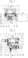
- the diaphragm pump is without the hydraulic parts that are not essential to the invention Drive system shown. This part is also called pump head 1.
- the hydraulic drive not shown, is connected to port 3.
- the drive can be chosen arbitrarily from the systems known per se.
- the hydraulic fluid is preferably relatively thin.
- the hydraulic chamber 7 In the interior of the drive part 5 of the pump head 1 there is the hydraulic chamber 7, which is closed off by the first diaphragm 9 on the drive side.
- the membrane 9 lies on a recessed surface 11 of the hydraulic chamber wall 13 which surrounds the opening of the hydraulic chamber 7.
- the membrane 9 is held by a fastening ring screwed against the wall 13, for which purpose a suitable number of screws 17 are used.
- a vent hole 19 is provided, which is closed by a screw 20.
- the pump system 22 is attached to the drive part 5 below.
- the pump chamber 24 in the pump system 22 is closed at the top by the pump-side membrane, in short pump membrane 26.
- the pump membrane 26 rests on a sealing surface 28 of the pump chamber wall 30. It is bordered on the edge by the fastening ring 15.
- the pump system 22 is screwed onto the drive part 5 by means of screws 32 (FIG. 3).
- screws 32 When the screws 32 are screwed in and tightened, the membranes 9 and 26 are pressed against one another and the latter against the sealing surface 28. Exact synchronization of the membranes 9 and 26 is achieved by a bubble-free oil or fat layer located between them.
- the membranes 9 and 26 are preferably made of metal or plastic, but need not be made of the same material.
- valve unit 36 is fastened by means of screws 38.
- An O-ring 40 is used to seal the separating surface.
- the pump chamber 24 also has a z. B. a screw lockable vent 41.
- the valve unit 36 consists of a three-way rotary slide valve 42 which can connect the access to the pump chamber 24 to the inlet 44 for the working medium or alternatively to the outlet 46.
- the valve 42 is actuated by its own drive 45. This drive must be synchronized with the hydraulic drive, for which purpose a control, not shown, is used. Such controls are known per se, as is the valve 42.
- the valve 42 consists, for. B. from a cylindrical valve body.
- the valve body contains a bore 47 angled by 90 °.
- the valve body 48 is rotatably arranged in a bush 49.
- O-rings 50 For sealing between the valve body 48 and the sleeve 49 there are two O-rings 50 each above and below the bore 47, and likewise between the sleeve 49 and the housing of the valve unit 36 two further O-rings 52.
- the outlet 46 is designed as a nozzle. In the preferred, pasty or highly viscous working media, free flow can be prevented, which, among other things, enables precise dosing.
- the present invention is particularly suitable for conveying highly viscous or pasty materials, which can also contain abrasive substances. These lead to rapid wear of the moving parts and thus, among other things, dosing errors. By changing in correspondingly short intervals, the one with the present Invention is possible without long downtimes, these adverse effects of wear and tear can be counteracted. After it has been removed from the drive system, a worn pump part can be repaired in parallel with the continued operation of the pump. In particular, it is also conceivable to carry out, in particular, parts subject to wear from less resistant, but cheaper and / or easier to dispose of material, e.g. B. the valve unit. It is therefore conceivable that the entire pump part or z. B. the valve as a moving part consists of a cheaper, but not extremely stable metal or plastic.
- the pump system can be attached to the drive part in such a way that a hydraulic oil is first applied to the membrane 9 and then the membrane 26 is placed on it. Care is taken to ensure that there are no air bubbles between the membranes. The easiest way to do this is by visual control. Then the actual pump system is attached and fastened by means of the screws 34. The pump system is filled with the working medium, the pump chamber 24 being vented via the vent hole 41.
- the pumping system is essentially removed in the reverse order. It is therefore not necessary to open the drive system when installing or removing the pump system, which would entail venting the hydraulics, among other things.
- the membrane pumps described are preferably designed for small volumes up to approximately 1 ml output per pump cycle.
- the membranes are preferably made of silicone and have a thickness of approximately 1 mm.
- Membranes made of metal, preferably made of steel, are for example 0.2-0.3 mm thick.
- the diaphragm pumps are particularly suitable for conveying viscous media and / or media loaded with abrasive materials.
- the diaphragm pumps can also be used advantageously where there is high wear on the pump due to corrosive properties of the media to be pumped.
Landscapes
- Engineering & Computer Science (AREA)
- Mechanical Engineering (AREA)
- General Engineering & Computer Science (AREA)
- Reciprocating Pumps (AREA)
Applications Claiming Priority (2)
| Application Number | Priority Date | Filing Date | Title |
|---|---|---|---|
| CH2055/94 | 1994-06-28 | ||
| CH205594 | 1994-06-28 |
Publications (1)
| Publication Number | Publication Date |
|---|---|
| EP0690232A1 true EP0690232A1 (fr) | 1996-01-03 |
Family
ID=4224873
Family Applications (1)
| Application Number | Title | Priority Date | Filing Date |
|---|---|---|---|
| EP95810368A Withdrawn EP0690232A1 (fr) | 1994-06-28 | 1995-06-06 | Pompe à membrane |
Country Status (1)
| Country | Link |
|---|---|
| EP (1) | EP0690232A1 (fr) |
Cited By (3)
| Publication number | Priority date | Publication date | Assignee | Title |
|---|---|---|---|---|
| EP0947814A3 (fr) * | 1998-03-30 | 2000-04-05 | Fresenius Medical Care Deutschland GmbH | Procédé de connection étanche à l'air de deux membranes |
| CN103423149A (zh) * | 2013-08-05 | 2013-12-04 | 宝鸡航天动力泵业有限公司 | 隔膜泵膜片快换式压紧机构 |
| EP3441612A1 (fr) * | 2017-08-08 | 2019-02-13 | Scheugenpflug AG | Unité de pompe, dispositif de stockage équipé d'une telle unité de pompe et procédé de fonctionnement dudit dispositif de stockage |
Citations (5)
| Publication number | Priority date | Publication date | Assignee | Title |
|---|---|---|---|---|
| GB283021A (en) * | 1927-03-28 | 1928-01-05 | Jean Donat Julien | Improvements relating to pumps |
| EP0441681A1 (fr) * | 1990-02-08 | 1991-08-14 | DOSAPRO MILTON ROY, SociÀ©té dite: | Perfectionnement à un dispositif détecteur de rupture de membrane dans une pompe à membrane double |
| DE9004560U1 (de) * | 1990-04-23 | 1991-08-22 | Bran + Luebbe GmbH, 2000 Norderstedt | Verbundmembran |
| DE4136097C1 (fr) * | 1991-11-02 | 1993-03-04 | Kloeckner Haensel Gmbh, 3000 Hannover, De | |
| US5282849A (en) * | 1991-12-19 | 1994-02-01 | University Of Utah Research Foundation | Ventricle assist device with volume displacement chamber |
-
1995
- 1995-06-06 EP EP95810368A patent/EP0690232A1/fr not_active Withdrawn
Patent Citations (5)
| Publication number | Priority date | Publication date | Assignee | Title |
|---|---|---|---|---|
| GB283021A (en) * | 1927-03-28 | 1928-01-05 | Jean Donat Julien | Improvements relating to pumps |
| EP0441681A1 (fr) * | 1990-02-08 | 1991-08-14 | DOSAPRO MILTON ROY, SociÀ©té dite: | Perfectionnement à un dispositif détecteur de rupture de membrane dans une pompe à membrane double |
| DE9004560U1 (de) * | 1990-04-23 | 1991-08-22 | Bran + Luebbe GmbH, 2000 Norderstedt | Verbundmembran |
| DE4136097C1 (fr) * | 1991-11-02 | 1993-03-04 | Kloeckner Haensel Gmbh, 3000 Hannover, De | |
| US5282849A (en) * | 1991-12-19 | 1994-02-01 | University Of Utah Research Foundation | Ventricle assist device with volume displacement chamber |
Cited By (6)
| Publication number | Priority date | Publication date | Assignee | Title |
|---|---|---|---|---|
| EP0947814A3 (fr) * | 1998-03-30 | 2000-04-05 | Fresenius Medical Care Deutschland GmbH | Procédé de connection étanche à l'air de deux membranes |
| US6484383B1 (en) | 1998-03-30 | 2002-11-26 | Fresenius Medical Care Deutschland Gmbh | Method of airtight bonding of two membranes |
| CN103423149A (zh) * | 2013-08-05 | 2013-12-04 | 宝鸡航天动力泵业有限公司 | 隔膜泵膜片快换式压紧机构 |
| CN103423149B (zh) * | 2013-08-05 | 2015-08-19 | 宝鸡航天动力泵业有限公司 | 隔膜泵膜片快换式压紧机构 |
| EP3441612A1 (fr) * | 2017-08-08 | 2019-02-13 | Scheugenpflug AG | Unité de pompe, dispositif de stockage équipé d'une telle unité de pompe et procédé de fonctionnement dudit dispositif de stockage |
| WO2019030001A1 (fr) * | 2017-08-08 | 2019-02-14 | Scheugenpflug Ag | Unité de pompage, dispositif de stockage équipé de celle-ci et procédé pour faire fonctionner le dispositif de stockage |
Similar Documents
| Publication | Publication Date | Title |
|---|---|---|
| EP0061630B1 (fr) | Pompe à engrenage à dispositif pour nettoyer | |
| DE4407679A1 (de) | Balgpumpe | |
| DE2127976A1 (de) | Dosier Kolbenpumpe | |
| DE1288392B (de) | Drehschieber | |
| DE1963875C3 (de) | Kolbenpumpe mit hydraulischem Antrieb zum Fördern von Beton | |
| DE2821801B2 (fr) | ||
| DE3152349A1 (en) | Back-flow prevention valve | |
| EP0690232A1 (fr) | Pompe à membrane | |
| DE3413437C2 (de) | Ventillose Membranpumpe | |
| DE4422819A1 (de) | Hochdruckpumpe | |
| DE69026945T2 (de) | Impulsfreie kolbenpumpe | |
| DE102006025653C5 (de) | Aseptisches Doppelsitzventil | |
| EP1348487B1 (fr) | Installation de revêtement avec un pulvérisateur et un pompe de dosage | |
| EP0099000B1 (fr) | Machine à piston ayant des cylindres en étoile | |
| DE69106916T2 (de) | Modulare Pumpe mit mehreren Auslässen, jeder versorgt durch eine Pumpeinheit. | |
| DE3507011A1 (de) | Fluessigkeitstransporteinrichtung vorzugsweise fuer farbstoffe und chemikalien | |
| DE19516578C1 (de) | Innenzahnradpumpe, geeigneet zur sterilen Reinigung im Durchlaufverfahren ohne Demontage | |
| DE102017126651B4 (de) | Pumpeinrichtung mit über einem gemeinsamen Antrieb gekoppelten Pumpen | |
| DE29507192U1 (de) | Pumpe zum Fördern von fließfähigen, insbesondere pastösen Stoffen, insbesondere für ein medizinisches Labor | |
| DE3710013A1 (de) | Membranverdraengerpumpe, insbesondere fuer reibende, korrosive fluessigkeiten mit in suspension befindlichen teilchen od. dgl. | |
| DE3023710C2 (fr) | ||
| DE60127467T2 (de) | Kontinuierliches Verdrängungsdosierventil | |
| DE2552828A1 (de) | Kolbensandpumpe | |
| DE693493C (de) | Handpumpe zum zeitweisen Foerdern von Schmiermittel mittels einer Fluegelkolbenpumpe | |
| WO1987006154A1 (fr) | Dispositif de dosage et de melange de systemes a composants fluides multiples |
Legal Events
| Date | Code | Title | Description |
|---|---|---|---|
| PUAI | Public reference made under article 153(3) epc to a published international application that has entered the european phase |
Free format text: ORIGINAL CODE: 0009012 |
|
| AK | Designated contracting states |
Kind code of ref document: A1 Designated state(s): CH DE FR IT LI NL |
|
| K1C1 | Correction of patent application (title page) published |
Effective date: 19960103 |
|
| STAA | Information on the status of an ep patent application or granted ep patent |
Free format text: STATUS: THE APPLICATION IS DEEMED TO BE WITHDRAWN |
|
| 18D | Application deemed to be withdrawn |
Effective date: 19960704 |