EP0690249A2 - Dispositif de commande de marche arrière pour boîte de vitesses d'un véhicule automobile - Google Patents
Dispositif de commande de marche arrière pour boîte de vitesses d'un véhicule automobile Download PDFInfo
- Publication number
- EP0690249A2 EP0690249A2 EP95109006A EP95109006A EP0690249A2 EP 0690249 A2 EP0690249 A2 EP 0690249A2 EP 95109006 A EP95109006 A EP 95109006A EP 95109006 A EP95109006 A EP 95109006A EP 0690249 A2 EP0690249 A2 EP 0690249A2
- Authority
- EP
- European Patent Office
- Prior art keywords
- switching
- switch
- reverse gear
- shift
- braking
- Prior art date
- Legal status (The legal status is an assumption and is not a legal conclusion. Google has not performed a legal analysis and makes no representation as to the accuracy of the status listed.)
- Granted
Links
Images


Classifications
-
- F—MECHANICAL ENGINEERING; LIGHTING; HEATING; WEAPONS; BLASTING
- F16—ENGINEERING ELEMENTS AND UNITS; GENERAL MEASURES FOR PRODUCING AND MAINTAINING EFFECTIVE FUNCTIONING OF MACHINES OR INSTALLATIONS; THERMAL INSULATION IN GENERAL
- F16H—GEARING
- F16H3/00—Toothed gearings for conveying rotary motion with variable gear ratio or for reversing rotary motion
- F16H3/02—Toothed gearings for conveying rotary motion with variable gear ratio or for reversing rotary motion without gears having orbital motion
- F16H3/20—Toothed gearings for conveying rotary motion with variable gear ratio or for reversing rotary motion without gears having orbital motion exclusively or essentially using gears that can be moved out of gear
- F16H3/38—Toothed gearings for conveying rotary motion with variable gear ratio or for reversing rotary motion without gears having orbital motion exclusively or essentially using gears that can be moved out of gear with synchro-meshing
- F16H3/385—Toothed gearings for conveying rotary motion with variable gear ratio or for reversing rotary motion without gears having orbital motion exclusively or essentially using gears that can be moved out of gear with synchro-meshing with braking means
-
- F—MECHANICAL ENGINEERING; LIGHTING; HEATING; WEAPONS; BLASTING
- F16—ENGINEERING ELEMENTS AND UNITS; GENERAL MEASURES FOR PRODUCING AND MAINTAINING EFFECTIVE FUNCTIONING OF MACHINES OR INSTALLATIONS; THERMAL INSULATION IN GENERAL
- F16H—GEARING
- F16H63/00—Control outputs from the control unit to change-speed- or reversing-gearings for conveying rotary motion or to other devices than the final output mechanism
- F16H63/02—Final output mechanisms therefor; Actuating means for the final output mechanisms
- F16H63/30—Constructional features of the final output mechanisms
- F16H63/302—Final output mechanisms for reversing
-
- F—MECHANICAL ENGINEERING; LIGHTING; HEATING; WEAPONS; BLASTING
- F16—ENGINEERING ELEMENTS AND UNITS; GENERAL MEASURES FOR PRODUCING AND MAINTAINING EFFECTIVE FUNCTIONING OF MACHINES OR INSTALLATIONS; THERMAL INSULATION IN GENERAL
- F16H—GEARING
- F16H61/00—Control functions within control units of change-speed- or reversing-gearings for conveying rotary motion ; Control of exclusively fluid gearing, friction gearing, gearings with endless flexible members or other particular types of gearing
- F16H61/26—Generation or transmission of movements for final actuating mechanisms
- F16H61/28—Generation or transmission of movements for final actuating mechanisms with at least one movement of the final actuating mechanism being caused by a non-mechanical force, e.g. power-assisted
- F16H61/32—Electric motors , actuators or related electrical control means therefor
Definitions
- the invention relates to a reverse gear shifting device for a motor vehicle gearbox of the type explained in the preamble of claim 1.
- the switch actuated by part of the shifting device lies in the region of the shift shaft actuated by the shift lever and is actuated when the level of the reverse gear is selected.
- An electromagnet is excited via a circuit which contains a time switch relay, the armature of which actuates a braking device of an expedient type.
- the known reverse gear shifting device has the disadvantage that the arrangement of the switch in the area of the shift shaft is more complex and, under certain circumstances, inconvenient to assemble or replace.
- the provision of a separate braking device for braking the trailing transmission shaft is expensive and takes up a lot of space.
- a switching device for reverse gear with braking of the input shaft of a motor vehicle change transmission in which one of the synchronizing devices of a forward gear not used for switching the reverse gear is used as a braking device.
- a switching device for reverse gear with braking of the input shaft of a motor vehicle change gearbox in which a switch arranged on the shift gate actuates an auxiliary brake device via an electro-hydraulic valve, care being taken in the design of the switch that he actuates the braking device only when engaging and not when disengaging reverse gear.
- the aim of the invention is to improve a reverse gear shifting device for a motor vehicle change transmission of the type explained in the preamble of claim 1 in such a way that a more versatile arrangement of the required switch becomes possible and a device already present in the transmission is used as a braking device.
- a shift aid should also be provided when engaging a forward gear.
- a reverse gear shifting device for a motor vehicle change transmission of the type explained in the preamble of claim 1 has the features indicated in the characterizing part of claim 1.
- the servo device is in a manner known per se an electromagnet which is actuated via a switch arranged on the shift lever or directly on a shift rod and directly on a shift rod, a Selector fork or a locking synchronizing ring acts, a versatile arrangement of the switch in the most favorable position and an arrangement of the electromagnet in the most favorable position for its effect.
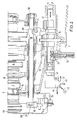
- an input shaft 2 and a countershaft 3 which are only partially shown, are arranged in a gearbox housing 1.
- Fixed gears 4 and 5 are arranged on the input shaft 2 and idler gears 6 and 7 for the third and fourth gears are arranged on the countershaft 3.
- a synchronous hub 8 is arranged in a conventional manner with a sliding sleeve 9, which can act on locking synchronizing rings 11 and 12 for shifting the third and fourth gears via synchronizing bolts 10.
- an additional housing 15 is arranged, into which the input shaft 2 and the countershaft 3 extend in the case of a 5-speed transmission and where a fixed gear 16 is arranged on the input shaft 2 and an idler gear 17 on the countershaft 3 for shifting a fifth gear.
- a synchronizing hub 18 with a sliding sleeve 19 and synchronizing bolts 20 is again arranged, which can act on a locking synchronizer ring 21.
- the additional housing 15 is further provided with a guide bore 22 for a shift rod 23 which carries a shift fork 24 with which it is in engagement with the sliding sleeve 19.
- the shift rod 23 with the shift fork 24 is actuated via a link lever 25, on which acts a bolt 26 which is shifted by the shift shaft 39 via the free end 40. (See FIG. 2)
- the link lever 25 carried by the pin 26 takes the shift rod 23 with it via a pin 27.
- the additional housing 15 is closed to the outside by a cover 28.
- a shift shaft 31 is axially displaceable and pivotable.
- the selector shaft 31 has shift detents 32 in connection with a spring catch 33.
- a locking disk 34 which is axially fixed in the housing, moves with a shift finger 35 (shown in dashed lines) in order to select one of a plurality of shift arms 36, 37 and 38 and then to move it axially.
- the switching arms 36 and 37 are mounted with corresponding sleeve approaches on a shift rod 39 axially displaceable.
- the shift arm 38 is fixedly connected to the shift rod 39, which is axially displaceable in the housing.
- the free end 40 of the shift rod 39 carries the bolt 26 by means of which the link lever 25 can be actuated to actuate the reverse gear.
- an electromagnet 41 is arranged directly in the extension of the bore 22 guiding the switching rod 23, the armature of which can exert a compressive force on the switching rod 23 as soon as the electromagnet is excited.
- a switch 42 is arranged in the extension of the bore carrying the selector shaft 31, the inputs and outputs of which are indicated in the directly connected switch symbol box.
- an input 43 of the switch 42 is connected to positive and successively establishes a connection to a line 44 to the electromagnet 41 and via a line 45 to a reversing light.
- Input 46 of switch 42 at plus and output 47 indicate the neutral position.
Landscapes
- Engineering & Computer Science (AREA)
- General Engineering & Computer Science (AREA)
- Mechanical Engineering (AREA)
- Gear-Shifting Mechanisms (AREA)
Applications Claiming Priority (2)
| Application Number | Priority Date | Filing Date | Title |
|---|---|---|---|
| DE4422427 | 1994-06-28 | ||
| DE4422427A DE4422427C2 (de) | 1994-06-28 | 1994-06-28 | Rückwärtsgang-Schaltvorrichtung für ein Kraftfahrzeug-Wechselgetriebe |
Publications (3)
| Publication Number | Publication Date |
|---|---|
| EP0690249A2 true EP0690249A2 (fr) | 1996-01-03 |
| EP0690249A3 EP0690249A3 (fr) | 1998-06-17 |
| EP0690249B1 EP0690249B1 (fr) | 2000-10-25 |
Family
ID=6521593
Family Applications (1)
| Application Number | Title | Priority Date | Filing Date |
|---|---|---|---|
| EP95109006A Expired - Lifetime EP0690249B1 (fr) | 1994-06-28 | 1995-06-12 | Dispositif de commande de marche arrière pour boíte de vitesses d'un véhicule automobile |
Country Status (3)
| Country | Link |
|---|---|
| EP (1) | EP0690249B1 (fr) |
| DE (2) | DE4422427C2 (fr) |
| ES (1) | ES2151005T3 (fr) |
Cited By (2)
| Publication number | Priority date | Publication date | Assignee | Title |
|---|---|---|---|---|
| FR2790810A1 (fr) * | 1999-03-12 | 2000-09-15 | Renault | Boite de vitesses a marche arriere synchronisee |
| WO2001069104A1 (fr) * | 2000-03-17 | 2001-09-20 | Renault | Boite de vitesses a marche arriere synchronisee |
Families Citing this family (2)
| Publication number | Priority date | Publication date | Assignee | Title |
|---|---|---|---|---|
| DE19928374C1 (de) * | 1999-06-21 | 2000-12-28 | Volkswagen Ag | Verfahren und Einrichtung zur Steuerung von Schaltvorgängen bei einem automatisierten Schaltgetriebe eines Kraftfahrzeuges |
| US7243575B2 (en) | 2002-03-25 | 2007-07-17 | Brp-Rotax Gmbh & Co. Kg | Braking mechanism for a gear |
Citations (3)
| Publication number | Priority date | Publication date | Assignee | Title |
|---|---|---|---|---|
| DE2319397A1 (de) | 1973-04-17 | 1974-10-24 | Ford Werke Ag | Synchronisiereinrichtung fuer den rueckwaertsgang eines kraftfahrzeuggetriebes |
| DE2933794A1 (de) | 1979-08-21 | 1981-03-26 | Ford-Werke AG, 50735 Köln | Rueckwaertsgang-schaltvorrichtung fuer ein kraftfahrzeugwechselgetriebe |
| DE2601418C2 (de) | 1975-01-15 | 1982-11-04 | Société Anonyme Automobiles Citroën, 75747 Paris | Schaltvorrichtung für ein Kraftfahrzeuggetriebe |
Family Cites Families (10)
| Publication number | Priority date | Publication date | Assignee | Title |
|---|---|---|---|---|
| DE1013179B (de) * | 1955-10-25 | 1957-08-01 | Zahnradfabrik Friedrichshafen | Elektromagnetisch betaetigte Klauenkupplung, insbesondere Gangschaltkupplung fuer Kraftfahrzeuge |
| FR1207451A (fr) * | 1957-06-26 | 1960-02-17 | Daimler Benz Ag | Accouplement susceptible d'être débrayé, en particulier pour changement de vitesse de voiture automobile et mécanisme de commande avec cet accouplement |
| DE2336250A1 (de) * | 1973-07-17 | 1975-02-06 | Porsche Ag | Rueckwaertsgang-schalteinrichtung fuer von hand schaltbare geschwindigkeitswechselgetriebe von kraftfahrzeugen |
| SE404999B (sv) * | 1977-05-09 | 1978-11-13 | Saab Scania Ab | Anordning for att underletta vexelmanovrering vid vexellador |
| US4273004A (en) * | 1978-07-25 | 1981-06-16 | Morrison William M | Gear selector mechanism |
| JPS57137747A (en) * | 1981-02-17 | 1982-08-25 | Toyota Motor Corp | Synchronizing device for speed changing gear |
| DE3138827A1 (de) * | 1981-09-30 | 1983-04-14 | Wabco Westinghouse Fahrzeugbremsen GmbH, 3000 Hannover | Gangwaehler fuer ein getriebe |
| JPS59120524A (ja) * | 1982-12-28 | 1984-07-12 | Isuzu Motors Ltd | 電子制御式変速機の変速操作方法 |
| JP3013363B2 (ja) * | 1989-09-30 | 2000-02-28 | スズキ株式会社 | 変速機の歯車打音防止装置 |
| DE4128834A1 (de) * | 1991-08-30 | 1993-03-04 | Zahnradfabrik Friedrichshafen | Zahnraederwechselgetriebe mit einer steuereinheit |
-
1994
- 1994-06-28 DE DE4422427A patent/DE4422427C2/de not_active Expired - Fee Related
-
1995
- 1995-06-12 ES ES95109006T patent/ES2151005T3/es not_active Expired - Lifetime
- 1995-06-12 EP EP95109006A patent/EP0690249B1/fr not_active Expired - Lifetime
- 1995-06-12 DE DE59508801T patent/DE59508801D1/de not_active Expired - Fee Related
Patent Citations (3)
| Publication number | Priority date | Publication date | Assignee | Title |
|---|---|---|---|---|
| DE2319397A1 (de) | 1973-04-17 | 1974-10-24 | Ford Werke Ag | Synchronisiereinrichtung fuer den rueckwaertsgang eines kraftfahrzeuggetriebes |
| DE2601418C2 (de) | 1975-01-15 | 1982-11-04 | Société Anonyme Automobiles Citroën, 75747 Paris | Schaltvorrichtung für ein Kraftfahrzeuggetriebe |
| DE2933794A1 (de) | 1979-08-21 | 1981-03-26 | Ford-Werke AG, 50735 Köln | Rueckwaertsgang-schaltvorrichtung fuer ein kraftfahrzeugwechselgetriebe |
Cited By (2)
| Publication number | Priority date | Publication date | Assignee | Title |
|---|---|---|---|---|
| FR2790810A1 (fr) * | 1999-03-12 | 2000-09-15 | Renault | Boite de vitesses a marche arriere synchronisee |
| WO2001069104A1 (fr) * | 2000-03-17 | 2001-09-20 | Renault | Boite de vitesses a marche arriere synchronisee |
Also Published As
| Publication number | Publication date |
|---|---|
| DE4422427A1 (de) | 1996-01-11 |
| EP0690249B1 (fr) | 2000-10-25 |
| DE59508801D1 (de) | 2000-11-30 |
| ES2151005T3 (es) | 2000-12-16 |
| EP0690249A3 (fr) | 1998-06-17 |
| DE4422427C2 (de) | 1996-06-05 |
Similar Documents
| Publication | Publication Date | Title |
|---|---|---|
| EP0107761B1 (fr) | Changement de vitesse pour transmission à commande par force séparée | |
| DE4208888B4 (de) | Anordnung zur Erfassung der Gangstellung eines Kraftfahrzeug-Schaltgetriebes | |
| DE4005588C2 (de) | Schaltvorrichtung für ein automatisches Getriebe | |
| EP1616116B1 (fr) | Boite de vitesses multi-etagee pour moteur a combustion interne | |
| DE3883924T2 (de) | Handschaltung für Splitterverbundgetriebe mit erweitertem Schaltbereich. | |
| DE3221634C2 (de) | Vorrichtung zum Betätigen eines Getriebes eines vierradgetriebenen Kraftfahrzeugs | |
| DE19737296C2 (de) | Selbsttätige Schaltvorrichtung eines Gangwechselgetriebes mit einem Handwählorgan | |
| DE69008167T2 (de) | Gangschalthebel für ein fahrzeuggetriebe. | |
| EP0616153B1 (fr) | Dispositif de changement de vitesse pour boîte de vitesses manuelle de véhicules à moteur | |
| DE69402101T2 (de) | Gangschaltungseinrichtung für ein automatisches Kraftfahrzeuggetriebe | |
| DE3011131C2 (fr) | ||
| EP0825364B1 (fr) | Dispositif de sélection pour boíte de vitesses automatique de véhicule automobile | |
| EP0412279A2 (fr) | Dispositif de changement de vitesses pour la boîte de vitesses d'une voiture | |
| DE69221426T2 (de) | Handbetätigtes Fahrzeuggetriebe | |
| DE4109942A1 (de) | Schaltgestaenge mit ein manuell schaltbares getriebe | |
| EP0690249A2 (fr) | Dispositif de commande de marche arrière pour boîte de vitesses d'un véhicule automobile | |
| WO1985001254A1 (fr) | Dispositif de changement de vitesse pour boite de vitesses manuelle de vehicules a moteur | |
| DE1930965A1 (de) | Schalteinrichtung fuer Kraftfahrzeugwechselgetriebe | |
| DE102013202272A1 (de) | Schalteinrichtung mit einer Schalt- und Wählwelle für ein Fahrzeuggetriebe | |
| EP0752546B1 (fr) | Mécanisme sélecteur de rapport pour boíte de vitesses semi-automatique de véhicule automobile | |
| DE102017209414A1 (de) | Getriebevorrichtung für einen Kraftwagen und Verfahren zum Betreiben einer Getriebevorrichtung | |
| DE69108399T2 (de) | Gangschaltvorrichtung. | |
| DE3115810C2 (de) | Zahnräderwechselgetriebe mit einem nachgeschalteten Dreibereichs-Gruppengetriebe | |
| AT404062B (de) | Geschwindigkeits-wechselgetriebe für kraftfahrzeuge | |
| DE19720780A1 (de) | Schaltsystem |
Legal Events
| Date | Code | Title | Description |
|---|---|---|---|
| PUAI | Public reference made under article 153(3) epc to a published international application that has entered the european phase |
Free format text: ORIGINAL CODE: 0009012 |
|
| AK | Designated contracting states |
Kind code of ref document: A2 Designated state(s): DE ES FR GB |
|
| PUAL | Search report despatched |
Free format text: ORIGINAL CODE: 0009013 |
|
| AK | Designated contracting states |
Kind code of ref document: A3 Designated state(s): DE ES FR GB |
|
| 17P | Request for examination filed |
Effective date: 19980514 |
|
| 17Q | First examination report despatched |
Effective date: 19981030 |
|
| GRAG | Despatch of communication of intention to grant |
Free format text: ORIGINAL CODE: EPIDOS AGRA |
|
| GRAG | Despatch of communication of intention to grant |
Free format text: ORIGINAL CODE: EPIDOS AGRA |
|
| GRAH | Despatch of communication of intention to grant a patent |
Free format text: ORIGINAL CODE: EPIDOS IGRA |
|
| GRAH | Despatch of communication of intention to grant a patent |
Free format text: ORIGINAL CODE: EPIDOS IGRA |
|
| GRAA | (expected) grant |
Free format text: ORIGINAL CODE: 0009210 |
|
| AK | Designated contracting states |
Kind code of ref document: B1 Designated state(s): DE ES FR GB |
|
| GBT | Gb: translation of ep patent filed (gb section 77(6)(a)/1977) |
Effective date: 20001025 |
|
| REF | Corresponds to: |
Ref document number: 59508801 Country of ref document: DE Date of ref document: 20001130 |
|
| REG | Reference to a national code |
Ref country code: ES Ref legal event code: FG2A Ref document number: 2151005 Country of ref document: ES Kind code of ref document: T3 |
|
| ET | Fr: translation filed | ||
| PLBE | No opposition filed within time limit |
Free format text: ORIGINAL CODE: 0009261 |
|
| STAA | Information on the status of an ep patent application or granted ep patent |
Free format text: STATUS: NO OPPOSITION FILED WITHIN TIME LIMIT |
|
| 26N | No opposition filed | ||
| REG | Reference to a national code |
Ref country code: GB Ref legal event code: IF02 |
|
| REG | Reference to a national code |
Ref country code: FR Ref legal event code: TP |
|
| REG | Reference to a national code |
Ref country code: FR Ref legal event code: CD Ref country code: FR Ref legal event code: CA |
|
| PGFP | Annual fee paid to national office [announced via postgrant information from national office to epo] |
Ref country code: ES Payment date: 20070619 Year of fee payment: 13 |
|
| PGFP | Annual fee paid to national office [announced via postgrant information from national office to epo] |
Ref country code: DE Payment date: 20070629 Year of fee payment: 13 |
|
| PGFP | Annual fee paid to national office [announced via postgrant information from national office to epo] |
Ref country code: GB Payment date: 20070511 Year of fee payment: 13 |
|
| PGFP | Annual fee paid to national office [announced via postgrant information from national office to epo] |
Ref country code: FR Payment date: 20070605 Year of fee payment: 13 |
|
| GBPC | Gb: european patent ceased through non-payment of renewal fee |
Effective date: 20080612 |
|
| REG | Reference to a national code |
Ref country code: FR Ref legal event code: ST Effective date: 20090228 |
|
| PG25 | Lapsed in a contracting state [announced via postgrant information from national office to epo] |
Ref country code: DE Free format text: LAPSE BECAUSE OF NON-PAYMENT OF DUE FEES Effective date: 20090101 |
|
| PG25 | Lapsed in a contracting state [announced via postgrant information from national office to epo] |
Ref country code: GB Free format text: LAPSE BECAUSE OF NON-PAYMENT OF DUE FEES Effective date: 20080612 |
|
| REG | Reference to a national code |
Ref country code: ES Ref legal event code: FD2A Effective date: 20080613 |
|
| PG25 | Lapsed in a contracting state [announced via postgrant information from national office to epo] |
Ref country code: FR Free format text: LAPSE BECAUSE OF NON-PAYMENT OF DUE FEES Effective date: 20080630 |
|
| PG25 | Lapsed in a contracting state [announced via postgrant information from national office to epo] |
Ref country code: ES Free format text: LAPSE BECAUSE OF NON-PAYMENT OF DUE FEES Effective date: 20080613 |