EP0690260B1 - Procédé de remplacement d'un élément de machine - Google Patents
Procédé de remplacement d'un élément de machine Download PDFInfo
- Publication number
- EP0690260B1 EP0690260B1 EP95810406A EP95810406A EP0690260B1 EP 0690260 B1 EP0690260 B1 EP 0690260B1 EP 95810406 A EP95810406 A EP 95810406A EP 95810406 A EP95810406 A EP 95810406A EP 0690260 B1 EP0690260 B1 EP 0690260B1
- Authority
- EP
- European Patent Office
- Prior art keywords
- metal
- metal frame
- machine
- machine part
- supports
- Prior art date
- Legal status (The legal status is an assumption and is not a legal conclusion. Google has not performed a legal analysis and makes no representation as to the accuracy of the status listed.)
- Expired - Lifetime
Links
Images

Classifications
-
- F—MECHANICAL ENGINEERING; LIGHTING; HEATING; WEAPONS; BLASTING
- F01—MACHINES OR ENGINES IN GENERAL; ENGINE PLANTS IN GENERAL; STEAM ENGINES
- F01D—NON-POSITIVE DISPLACEMENT MACHINES OR ENGINES, e.g. STEAM TURBINES
- F01D25/00—Component parts, details, or accessories, not provided for in, or of interest apart from, other groups
- F01D25/28—Supporting or mounting arrangements, e.g. for turbine casing
- F01D25/285—Temporary support structures, e.g. for testing, assembling, installing, repairing; Assembly methods using such structures
-
- F—MECHANICAL ENGINEERING; LIGHTING; HEATING; WEAPONS; BLASTING
- F01—MACHINES OR ENGINES IN GENERAL; ENGINE PLANTS IN GENERAL; STEAM ENGINES
- F01D—NON-POSITIVE DISPLACEMENT MACHINES OR ENGINES, e.g. STEAM TURBINES
- F01D25/00—Component parts, details, or accessories, not provided for in, or of interest apart from, other groups
- F01D25/28—Supporting or mounting arrangements, e.g. for turbine casing
-
- F—MECHANICAL ENGINEERING; LIGHTING; HEATING; WEAPONS; BLASTING
- F01—MACHINES OR ENGINES IN GENERAL; ENGINE PLANTS IN GENERAL; STEAM ENGINES
- F01K—STEAM ENGINE PLANTS; STEAM ACCUMULATORS; ENGINE PLANTS NOT OTHERWISE PROVIDED FOR; ENGINES USING SPECIAL WORKING FLUIDS OR CYCLES
- F01K13/00—General layout or general methods of operation of complete plants
- F01K13/006—Auxiliaries or details not otherwise provided for
-
- F—MECHANICAL ENGINEERING; LIGHTING; HEATING; WEAPONS; BLASTING
- F16—ENGINEERING ELEMENTS AND UNITS; GENERAL MEASURES FOR PRODUCING AND MAINTAINING EFFECTIVE FUNCTIONING OF MACHINES OR INSTALLATIONS; THERMAL INSULATION IN GENERAL
- F16M—FRAMES, CASINGS OR BEDS OF ENGINES, MACHINES OR APPARATUS, NOT SPECIFIC TO ENGINES, MACHINES OR APPARATUS PROVIDED FOR ELSEWHERE; STANDS; SUPPORTS
- F16M5/00—Engine beds, i.e. means for supporting engines or machines on foundations
-
- Y—GENERAL TAGGING OF NEW TECHNOLOGICAL DEVELOPMENTS; GENERAL TAGGING OF CROSS-SECTIONAL TECHNOLOGIES SPANNING OVER SEVERAL SECTIONS OF THE IPC; TECHNICAL SUBJECTS COVERED BY FORMER USPC CROSS-REFERENCE ART COLLECTIONS [XRACs] AND DIGESTS
- Y10—TECHNICAL SUBJECTS COVERED BY FORMER USPC
- Y10T—TECHNICAL SUBJECTS COVERED BY FORMER US CLASSIFICATION
- Y10T29/00—Metal working
- Y10T29/49—Method of mechanical manufacture
- Y10T29/49229—Prime mover or fluid pump making
- Y10T29/49231—I.C. [internal combustion] engine making
- Y10T29/49233—Repairing, converting, servicing or salvaging
-
- Y—GENERAL TAGGING OF NEW TECHNOLOGICAL DEVELOPMENTS; GENERAL TAGGING OF CROSS-SECTIONAL TECHNOLOGIES SPANNING OVER SEVERAL SECTIONS OF THE IPC; TECHNICAL SUBJECTS COVERED BY FORMER USPC CROSS-REFERENCE ART COLLECTIONS [XRACs] AND DIGESTS
- Y10—TECHNICAL SUBJECTS COVERED BY FORMER USPC
- Y10T—TECHNICAL SUBJECTS COVERED BY FORMER US CLASSIFICATION
- Y10T29/00—Metal working
- Y10T29/49—Method of mechanical manufacture
- Y10T29/49316—Impeller making
- Y10T29/49318—Repairing or disassembling
-
- Y—GENERAL TAGGING OF NEW TECHNOLOGICAL DEVELOPMENTS; GENERAL TAGGING OF CROSS-SECTIONAL TECHNOLOGIES SPANNING OVER SEVERAL SECTIONS OF THE IPC; TECHNICAL SUBJECTS COVERED BY FORMER USPC CROSS-REFERENCE ART COLLECTIONS [XRACs] AND DIGESTS
- Y10—TECHNICAL SUBJECTS COVERED BY FORMER USPC
- Y10T—TECHNICAL SUBJECTS COVERED BY FORMER US CLASSIFICATION
- Y10T29/00—Metal working
- Y10T29/49—Method of mechanical manufacture
- Y10T29/49718—Repairing
- Y10T29/49721—Repairing with disassembling
- Y10T29/4973—Replacing of defective part
-
- Y—GENERAL TAGGING OF NEW TECHNOLOGICAL DEVELOPMENTS; GENERAL TAGGING OF CROSS-SECTIONAL TECHNOLOGIES SPANNING OVER SEVERAL SECTIONS OF THE IPC; TECHNICAL SUBJECTS COVERED BY FORMER USPC CROSS-REFERENCE ART COLLECTIONS [XRACs] AND DIGESTS
- Y10—TECHNICAL SUBJECTS COVERED BY FORMER USPC
- Y10T—TECHNICAL SUBJECTS COVERED BY FORMER US CLASSIFICATION
- Y10T29/00—Metal working
- Y10T29/53—Means to assemble or disassemble
- Y10T29/53983—Work-supported apparatus
Definitions
- the invention relates to a method for exchanging a Machine part of a machine system, the relevant, coupled machine parts on a common Table top are arranged, which over individual supports in Ground either anchored directly or via a sole plate and which recesses for receiving the machine parts owns.
- the multi-housing machine is considered to be such a machine system Turbo group of a steam power plant, the machine parts in the form of the individual turbine parts and the generator given are.
- Such a system and an exchange method according to the preamble of the independent claims are known from EP-A-246 470.
- the size of the recess in the table top must be adapted to the dimensions of the new machine part. This is done with an enlargement of the recess by prying off concrete and cutting off reinforcing bars. If the cut-out has to be reduced, the reinforcing bars are exposed by stripping concrete, new reinforcing bars are applied, shuttered and concreted on. This concrete work generates a lot of noise and dust and is very time-consuming, and therefore very cost-intensive due to the long downtime of the steam turbine group.
- the reduction in the recess of the table top is included particularly time-consuming because the exposure and application of the Reinforcing iron has to be done very carefully on the concrete surfaces are to be handled and prepared carefully, for a stable connection between the table top and the to achieve newly applied concrete.
- the invention has for its object in a method to replace a machine part of a machine system time-consuming and therefore costly Avoid concrete work when downsizing the recess of the table top arise.
- the advantages of the invention include that the time required to replace a machine part is significantly reduced, complex concrete work is no longer necessary.
- the machine part can be switched off before the steam turbine group is switched off be assembled and checked, what as the above advantage the downtime of the steam turbine group is reduced. Since the metal frame is supported separately, can be dynamic behavior due to the number of metal supports and their Dimension can be influenced positively.
- the metal frame is adjustable connected to the table top, so that dynamic behavior of the machine-metal frame unit is not affected by the table top.
- the machine system according to Fig. 1 represents a steam turbine group represents, consisting essentially of a high pressure turbine 1, a medium-pressure turbine section 2 and a low-pressure turbine section 3 connected to a capacitor 4 is.
- the sub-turbines are among themselves and with one Generator 5 and an exciter 6 coupled.
- the turbo group stands on a foundation, which is composed here from a table top 7, several individual supports 8 and one Sole plate 9. From the table top 7 are only the crossbars can be seen, the sole plate 9 lies on the ground on.
- Fig. 2 shows a bare foundation for a turbo group with a low-pressure turbine part 3, for which the recess 10 is provided.
- the recess 11 receives the generator. It can be a monolithic concrete foundation as well also act as a spring foundation with individual supports.
- the machine part 5a to be replaced is shown below and the new machine part 5b to be coupled generators, while as the remaining machine parts the entirety of the Turbines 1-3 apply.
- a metal frame 12 is built on it.
- the metal frame 12 is designed in such a way that its outer dimension is smaller than the recess 11 of the table top and that its inner dimension is larger than the new generator 5b.
- the generator 5b is erected on the metal frame 12.
- the stator is attached, the bearing blocks are assembled, the rotor is moved into the stator and placed in the bearings.
- the generator is aligned for its end position and firmly connected to the metal frame 12.
- the unit of new generator 5b and metal frame 12 is called the exchange unit below.
- the electrical test is carried out using an electric motor, not shown.
- a Created lifting device that enables the generators to lift and move. Acting in this lifting device it is usually a mobile crane system that is used in the drawings is not shown.
- the exchange phase begins with the Turbo group of generator 5a uncoupled from turbine 3 is released from the table top 7 with the lifting device removed and parked next to the machine.
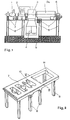
- Fig.3 and 4 introduced at least four metal supports 13 and on the Sole plate 9 attached.
- a possible type of attachment would be for example a screw connection with subsequent pouring of concrete.
- the metal frame 12 is with the metal supports 13 firmly connected, for example by a Screw connection.
- the metal frame 12 is additionally in accordance with FIGS. 3 and 4 adjustable connected to the table top 7. This will for example on the table top 7 with a metal plate a rectangular groove 20 and one on the metal frame as well shaped metal wedge 21 attached.
- Figure 4 is for illustration a possible solution with four keyway systems drawn.
- the invention is not as shown and described methods limited.
- the design of the Metal frame and metal supports can also be considered of the geometric requirements, in another way take place, this with particular regard to the desired dynamic behavior.
- For the adjustable connection of the metal frame and table top are basically any other groove-wedge shape and arrangements suitable.
Landscapes
- Engineering & Computer Science (AREA)
- General Engineering & Computer Science (AREA)
- Mechanical Engineering (AREA)
- Chemical & Material Sciences (AREA)
- Combustion & Propulsion (AREA)
- Manufacture Of Motors, Generators (AREA)
- Foundations (AREA)
- Bending Of Plates, Rods, And Pipes (AREA)
- Diaphragms For Electromechanical Transducers (AREA)
- Investigating Strength Of Materials By Application Of Mechanical Stress (AREA)
- Lift-Guide Devices, And Elevator Ropes And Cables (AREA)
- Working Measures On Existing Buildindgs (AREA)
- Numerical Control (AREA)
- Processing Of Stones Or Stones Resemblance Materials (AREA)
- Punching Or Piercing (AREA)
Claims (5)
- Procédé de remplacement d'un élément de machine (5a) d'une installation motrice, dont les éléments de 5 machine (1-6) principaux accouplés les uns aux autres sont disposés sur un plateau de table (7) commun, qui est ancré, par l'intermédiaire de supports individuels (8) dans le sol soit directement, soit par le biais d'une semelle (9), et qui possède des évidements (10, 11) pour recevoir les éléments de machine, caractérisé en ce quedans une phase de préparationdans la zone de l'installation motrice, on érige un cadre métallique (12), sur lequel est prémonté, orienté et testé un nouvel élément de machine (5b) pourvu de paliers,et en ce que dans une phase de remplacementl'élément de machine (5a) à remplacer est désaccouplé des éléments de machine restants (1-3) et est retiré du plateau de table (7) au moyen de leviers,en ce que des supports métalliques (13) sont montés dans la zone de l'évidement (11) du plateau de table et sont reliés à la semelle (9) ou au sol,et en ce que le nouvel élément de machine (5b) conjointement au cadre métallique (12) est déposé au moyen de leviers sur les supports métalliques (13) et est relié aux supports métalliques après l'orientation finale.
- Procédé selon la revendication 1, caractérisé en ce que le cadre métallique (12) est relié de manière ajustable au plateau de table (7).
- Procédé selon la revendication 2, caractérisé en ce que la liaison ajustable est un système de rainure et clavette.
- Procédé selon la revendication 1, caractérisé en ce que l'on obtient le comportement dynamique souhaité du nouvel élément de machine grâce au nombre et à la forme des supports métalliques (13).
- Unité de remplacement (5b, 12) pour réaliser le procédé selon la revendication 1, caractérisée par un élément de machine (5b) fixé sur un cadre métallique (12) et préorienté, qui est engagé avec un jeu latéral dans un évidement (11) d'un plateau de table (7) et est disposé sur plusieurs supports métalliques (13) faisant saillie dans l'évidement (11) et fixés au sol ou à la semelle (9).
Applications Claiming Priority (2)
| Application Number | Priority Date | Filing Date | Title |
|---|---|---|---|
| DE4423324A DE4423324A1 (de) | 1994-07-02 | 1994-07-02 | Verfahren zum Austausch eines Maschinenteils |
| DE4423324 | 1994-07-02 |
Publications (2)
| Publication Number | Publication Date |
|---|---|
| EP0690260A1 EP0690260A1 (fr) | 1996-01-03 |
| EP0690260B1 true EP0690260B1 (fr) | 1998-10-07 |
Family
ID=6522158
Family Applications (1)
| Application Number | Title | Priority Date | Filing Date |
|---|---|---|---|
| EP95810406A Expired - Lifetime EP0690260B1 (fr) | 1994-07-02 | 1995-06-19 | Procédé de remplacement d'un élément de machine |
Country Status (10)
| Country | Link |
|---|---|
| US (2) | US5675881A (fr) |
| EP (1) | EP0690260B1 (fr) |
| JP (1) | JPH0842305A (fr) |
| CN (1) | CN1046579C (fr) |
| AT (1) | ATE172015T1 (fr) |
| CZ (1) | CZ290294B6 (fr) |
| DE (2) | DE4423324A1 (fr) |
| HR (1) | HRP950229B1 (fr) |
| RU (1) | RU2144642C1 (fr) |
| UA (1) | UA34470C2 (fr) |
Families Citing this family (13)
| Publication number | Priority date | Publication date | Assignee | Title |
|---|---|---|---|---|
| DE19755981B4 (de) * | 1997-12-17 | 2005-09-15 | Alstom | Dampfturbinenanlage |
| DE19849233A1 (de) * | 1998-10-26 | 2000-04-27 | Fritz Stahlecker | Verfahren zum Auswechseln von Lagern einer changierenden Fadenführerstange |
| US6502291B2 (en) * | 1998-10-26 | 2003-01-07 | Fritz Stahlecker | Process for exchanging the bearings of a traversing fiber guiding rod and textile machine accommodating same |
| EP1004751B1 (fr) * | 1998-11-25 | 2003-02-26 | Alstom Power Generation AG | Centrale à vapeur arrangée à ciel ouvert |
| RU2263247C2 (ru) * | 2003-10-10 | 2005-10-27 | Общество с ограниченной ответственностью "Газтехноинвест" | Способ монтажа турбокомпрессорного агрегата |
| US20060059812A1 (en) * | 2004-08-30 | 2006-03-23 | Simmons Robert J | Column base to podium slab anchoring |
| US9032620B2 (en) * | 2008-12-12 | 2015-05-19 | Nuovo Pignone S.P.A. | Method for moving and aligning heavy device |
| US8662821B2 (en) * | 2010-12-29 | 2014-03-04 | General Electric Company | Removable steam inlet assembly for steam turbine |
| CN102624147B (zh) * | 2011-01-26 | 2016-03-23 | 阿尔斯通技术有限公司 | 改进发电厂的方法 |
| US8813500B2 (en) * | 2011-08-03 | 2014-08-26 | Dresser-Rand Company | Combined heat exchanger expander mounting system |
| RU2551446C2 (ru) * | 2012-06-29 | 2015-05-27 | Альстом Текнолоджи Лтд | Способ модернизации электростанции |
| KR101579042B1 (ko) * | 2015-09-02 | 2015-12-22 | 에이스기전 주식회사 | 터빈 조립체용 작업대 |
| CN110630852A (zh) * | 2019-11-06 | 2019-12-31 | 徐州市凯诺机械有限公司 | 一种起重机支撑装置 |
Family Cites Families (14)
| Publication number | Priority date | Publication date | Assignee | Title |
|---|---|---|---|---|
| DE203959C (fr) * | ||||
| DE852758C (de) * | 1941-01-07 | 1952-10-20 | Maschf Augsburg Nuernberg Ag | Fundamentaufbau einer Gasmaschinenpumpstation fuer Ferngasnetze |
| DE1015273B (de) * | 1953-08-19 | 1957-09-05 | Ernst Rausch Dr Ing | Verfahren zum Veraendern der Eigenfrequenz von Tragwerken |
| FR1474474A (fr) * | 1966-04-02 | 1967-03-24 | Ass Elect Ind | Groupes de turbines à vapeur de grande puissance |
| DE1551192A1 (de) * | 1967-04-28 | 1970-04-16 | Licentia Gmbh | Dampfturbine mit insbesondere in Doppelmantelbauweise ausgefuehrten Niederdruckteilen |
| JPS57165795A (en) * | 1981-04-03 | 1982-10-12 | Hitachi Ltd | Method of constructing atomic power turbine supporting table |
| DD203959A1 (de) * | 1981-12-04 | 1983-11-09 | Werner Birke | Einrichtung zur weiterverwendung vorhandener betonfundamente fuer rekonstruierte dampfturbosaetze |
| US4694190A (en) * | 1985-12-23 | 1987-09-15 | General Electric Company | Integral generator housing and base for a turbine generator |
| CH672540A5 (fr) * | 1986-05-19 | 1989-11-30 | Bbc Brown Boveri & Cie | |
| SU1444581A1 (ru) * | 1986-09-08 | 1988-12-15 | Центральный Научно-Исследовательский И Проектно-Конструкторский Институт Механизации И Энергетики Лесной Промышленности | Способ монтажа технологического оборудовани |
| DD272119A1 (de) * | 1988-04-21 | 1989-09-27 | Goerlitzer Maschinenbau Veb | Zwischenstueck fuer vorhandene turbosatzfundamente bei kraftwerksrekonstruktionen |
| DD277496A1 (de) * | 1988-12-02 | 1990-04-04 | Dessau Zementanlagenbau Veb | Anordnung zur montage von schweren ausruestungen |
| DE4015693A1 (de) * | 1990-05-16 | 1991-11-21 | Bosch Gmbh Robert | Traegerplatte und verfahren zu deren herstellung |
| US5224377A (en) * | 1992-08-12 | 1993-07-06 | Gei Systems, Inc. | Rigid test table for gear sets |
-
1994
- 1994-07-02 DE DE4423324A patent/DE4423324A1/de not_active Withdrawn
-
1995
- 1995-03-31 US US08/414,731 patent/US5675881A/en not_active Expired - Fee Related
- 1995-04-13 HR HRP4423324.8A patent/HRP950229B1/xx not_active IP Right Cessation
- 1995-05-26 UA UA95062991A patent/UA34470C2/uk unknown
- 1995-06-19 EP EP95810406A patent/EP0690260B1/fr not_active Expired - Lifetime
- 1995-06-19 DE DE59503834T patent/DE59503834D1/de not_active Expired - Fee Related
- 1995-06-19 AT AT95810406T patent/ATE172015T1/de not_active IP Right Cessation
- 1995-06-28 CN CN95107641A patent/CN1046579C/zh not_active Expired - Fee Related
- 1995-06-29 RU RU95110702A patent/RU2144642C1/ru not_active IP Right Cessation
- 1995-06-30 CZ CZ19951727A patent/CZ290294B6/cs not_active IP Right Cessation
- 1995-07-03 JP JP7167704A patent/JPH0842305A/ja not_active Abandoned
-
1997
- 1997-02-06 US US08/797,450 patent/US5992906A/en not_active Expired - Fee Related
Also Published As
| Publication number | Publication date |
|---|---|
| US5992906A (en) | 1999-11-30 |
| UA34470C2 (uk) | 2001-03-15 |
| CN1046579C (zh) | 1999-11-17 |
| CZ172795A3 (en) | 1997-03-12 |
| CN1116694A (zh) | 1996-02-14 |
| DE59503834D1 (de) | 1998-11-12 |
| CZ290294B6 (cs) | 2002-07-17 |
| JPH0842305A (ja) | 1996-02-13 |
| HRP950229B1 (en) | 1999-12-31 |
| RU95110702A (ru) | 1997-04-20 |
| DE4423324A1 (de) | 1996-01-04 |
| HRP950229A2 (en) | 1997-02-28 |
| ATE172015T1 (de) | 1998-10-15 |
| RU2144642C1 (ru) | 2000-01-20 |
| US5675881A (en) | 1997-10-14 |
| EP0690260A1 (fr) | 1996-01-03 |
Similar Documents
| Publication | Publication Date | Title |
|---|---|---|
| DE3877356T2 (de) | Verfahren und vorrichtung zur zusammensetzung kleiner elektrischer maschinen. | |
| EP0175075A1 (fr) | Machine électrique tournante | |
| EP0690260A1 (fr) | Procédé de remplacement d'un élément de machine | |
| DE2557920B2 (de) | Vorrichtung zum Befestigen eines Lagers auf einem Betonsockel | |
| EP0246470B1 (fr) | Méthode pour remplacer un élément de machine | |
| WO2008125506A1 (fr) | Dispositif de fixation destiné à fixer un rotor d'une turbomachine, disposé perpendiculairement par rapport à un plan horizontal, contre le basculement, et procédé d'orientation destiné à cet effet | |
| WO2013056807A1 (fr) | Presse | |
| EP2847390A1 (fr) | Système d'ancrage dans une fondation pour machines industrielles | |
| CH676876A5 (fr) | ||
| DE60203128T2 (de) | Universalwalzgerüst mit walzspaltregelung | |
| DE3200815A1 (de) | Verfahren zum ausrichten der wellen von elastisch aufgestellten maschinen | |
| EP0369269B1 (fr) | Dispositif d'entrée ou de sortie de produits laminés, en particulier de profilés, entre les cylindres de cages de laminoir | |
| EP3494259A1 (fr) | Dispositif d'étaiement de pont pour l'étaiement d'un segment de pont et procédé pour faire fonctionner des dispositifs d'étaiement de pont | |
| DE102023135717A1 (de) | Teleskopierbarer Gittermastturm und Verfahren zum Heben eines teleskopierbaren Gittermastturms | |
| DE3030791A1 (de) | Vorrichtung zum gezielten anheben einer last | |
| EP0766075B1 (fr) | Procédé pour tester simultanément plusieurs capteurs de forces, en particulier capteurs de pesage, utilisant une charge | |
| EP0911948A2 (fr) | Gros moteur électrique | |
| DE2202604C2 (de) | Federnde Statorabstützung einer Synchronmaschine | |
| DE3942410C2 (fr) | ||
| DE1015273B (de) | Verfahren zum Veraendern der Eigenfrequenz von Tragwerken | |
| DE4403442C1 (de) | Fixator zwischen einem Fundament und einem Maschinenbett | |
| DE102016011189A1 (de) | Vorrichtung zum Stabilisieren eines Krans | |
| DE202022001515U1 (de) | Vorrichtung zum Abbau einer Brücke | |
| DE2449315A1 (de) | Verfahren zur errichtung eines bockkranes | |
| DD251190A1 (de) | Lagerungen eines schnellverseilmaschinenrotors |
Legal Events
| Date | Code | Title | Description |
|---|---|---|---|
| PUAI | Public reference made under article 153(3) epc to a published international application that has entered the european phase |
Free format text: ORIGINAL CODE: 0009012 |
|
| AK | Designated contracting states |
Kind code of ref document: A1 Designated state(s): AT DE FR GB IT |
|
| 17P | Request for examination filed |
Effective date: 19960603 |
|
| RAP1 | Party data changed (applicant data changed or rights of an application transferred) |
Owner name: ASEA BROWN BOVERI AG |
|
| GRAG | Despatch of communication of intention to grant |
Free format text: ORIGINAL CODE: EPIDOS AGRA |
|
| 17Q | First examination report despatched |
Effective date: 19971212 |
|
| GRAG | Despatch of communication of intention to grant |
Free format text: ORIGINAL CODE: EPIDOS AGRA |
|
| GRAH | Despatch of communication of intention to grant a patent |
Free format text: ORIGINAL CODE: EPIDOS IGRA |
|
| GRAH | Despatch of communication of intention to grant a patent |
Free format text: ORIGINAL CODE: EPIDOS IGRA |
|
| GRAA | (expected) grant |
Free format text: ORIGINAL CODE: 0009210 |
|
| AK | Designated contracting states |
Kind code of ref document: B1 Designated state(s): AT DE FR GB IT |
|
| REF | Corresponds to: |
Ref document number: 172015 Country of ref document: AT Date of ref document: 19981015 Kind code of ref document: T |
|
| REF | Corresponds to: |
Ref document number: 59503834 Country of ref document: DE Date of ref document: 19981112 |
|
| GBT | Gb: translation of ep patent filed (gb section 77(6)(a)/1977) |
Effective date: 19981210 |
|
| ET | Fr: translation filed | ||
| PLBE | No opposition filed within time limit |
Free format text: ORIGINAL CODE: 0009261 |
|
| STAA | Information on the status of an ep patent application or granted ep patent |
Free format text: STATUS: NO OPPOSITION FILED WITHIN TIME LIMIT |
|
| 26N | No opposition filed | ||
| REG | Reference to a national code |
Ref country code: GB Ref legal event code: IF02 |
|
| REG | Reference to a national code |
Ref country code: GB Ref legal event code: 732E |
|
| PGFP | Annual fee paid to national office [announced via postgrant information from national office to epo] |
Ref country code: GB Payment date: 20030530 Year of fee payment: 9 |
|
| PGFP | Annual fee paid to national office [announced via postgrant information from national office to epo] |
Ref country code: DE Payment date: 20030603 Year of fee payment: 9 Ref country code: AT Payment date: 20030603 Year of fee payment: 9 |
|
| PGFP | Annual fee paid to national office [announced via postgrant information from national office to epo] |
Ref country code: FR Payment date: 20030611 Year of fee payment: 9 |
|
| REG | Reference to a national code |
Ref country code: FR Ref legal event code: CD Ref country code: FR Ref legal event code: CA |
|
| PG25 | Lapsed in a contracting state [announced via postgrant information from national office to epo] |
Ref country code: GB Free format text: LAPSE BECAUSE OF NON-PAYMENT OF DUE FEES Effective date: 20040619 Ref country code: AT Free format text: LAPSE BECAUSE OF NON-PAYMENT OF DUE FEES Effective date: 20040619 |
|
| REG | Reference to a national code |
Ref country code: FR Ref legal event code: TP |
|
| PG25 | Lapsed in a contracting state [announced via postgrant information from national office to epo] |
Ref country code: DE Free format text: LAPSE BECAUSE OF NON-PAYMENT OF DUE FEES Effective date: 20050101 |
|
| GBPC | Gb: european patent ceased through non-payment of renewal fee |
Effective date: 20040619 |
|
| PG25 | Lapsed in a contracting state [announced via postgrant information from national office to epo] |
Ref country code: FR Free format text: LAPSE BECAUSE OF NON-PAYMENT OF DUE FEES Effective date: 20050228 |
|
| REG | Reference to a national code |
Ref country code: FR Ref legal event code: ST |
|
| PG25 | Lapsed in a contracting state [announced via postgrant information from national office to epo] |
Ref country code: IT Free format text: LAPSE BECAUSE OF NON-PAYMENT OF DUE FEES;WARNING: LAPSES OF ITALIAN PATENTS WITH EFFECTIVE DATE BEFORE 2007 MAY HAVE OCCURRED AT ANY TIME BEFORE 2007. THE CORRECT EFFECTIVE DATE MAY BE DIFFERENT FROM THE ONE RECORDED. Effective date: 20050619 |