EP0690550A2 - Supraleitender Rotor für eine elektrische Maschine - Google Patents
Supraleitender Rotor für eine elektrische Maschine Download PDFInfo
- Publication number
- EP0690550A2 EP0690550A2 EP95304459A EP95304459A EP0690550A2 EP 0690550 A2 EP0690550 A2 EP 0690550A2 EP 95304459 A EP95304459 A EP 95304459A EP 95304459 A EP95304459 A EP 95304459A EP 0690550 A2 EP0690550 A2 EP 0690550A2
- Authority
- EP
- European Patent Office
- Prior art keywords
- superconductive
- generally
- thermal shield
- rotor
- solid core
- Prior art date
- Legal status (The legal status is an assumption and is not a legal conclusion. Google has not performed a legal analysis and makes no representation as to the accuracy of the status listed.)
- Granted
Links
- 239000007787 solid Substances 0.000 claims abstract description 33
- 238000012546 transfer Methods 0.000 claims abstract description 27
- 230000008878 coupling Effects 0.000 claims abstract description 24
- 238000010168 coupling process Methods 0.000 claims abstract description 24
- 238000005859 coupling reaction Methods 0.000 claims abstract description 24
- 238000001816 cooling Methods 0.000 claims abstract description 18
- 125000006850 spacer group Chemical group 0.000 claims description 18
- 239000000725 suspension Substances 0.000 claims description 12
- 238000004891 communication Methods 0.000 claims description 8
- 239000012530 fluid Substances 0.000 claims description 8
- 229910001220 stainless steel Inorganic materials 0.000 claims description 7
- 239000010935 stainless steel Substances 0.000 claims description 6
- KJSMVPYGGLPWOE-UHFFFAOYSA-N niobium tin Chemical compound [Nb].[Sn] KJSMVPYGGLPWOE-UHFFFAOYSA-N 0.000 claims description 4
- 229910000657 niobium-tin Inorganic materials 0.000 claims description 4
- RYGMFSIKBFXOCR-UHFFFAOYSA-N Copper Chemical compound [Cu] RYGMFSIKBFXOCR-UHFFFAOYSA-N 0.000 claims description 3
- 239000010949 copper Substances 0.000 claims description 3
- 229910052802 copper Inorganic materials 0.000 claims description 3
- 239000003381 stabilizer Substances 0.000 claims description 2
- 239000001307 helium Substances 0.000 abstract description 14
- 229910052734 helium Inorganic materials 0.000 abstract description 14
- SWQJXJOGLNCZEY-UHFFFAOYSA-N helium atom Chemical compound [He] SWQJXJOGLNCZEY-UHFFFAOYSA-N 0.000 abstract description 11
- XEEYBQQBJWHFJM-UHFFFAOYSA-N Iron Chemical group [Fe] XEEYBQQBJWHFJM-UHFFFAOYSA-N 0.000 abstract description 4
- 239000007789 gas Substances 0.000 description 13
- 238000013461 design Methods 0.000 description 8
- 230000005291 magnetic effect Effects 0.000 description 6
- 229910052782 aluminium Inorganic materials 0.000 description 4
- XAGFODPZIPBFFR-UHFFFAOYSA-N aluminium Chemical compound [Al] XAGFODPZIPBFFR-UHFFFAOYSA-N 0.000 description 4
- 239000007788 liquid Substances 0.000 description 4
- OKTJSMMVPCPJKN-UHFFFAOYSA-N Carbon Chemical compound [C] OKTJSMMVPCPJKN-UHFFFAOYSA-N 0.000 description 3
- 239000004593 Epoxy Substances 0.000 description 3
- 230000008901 benefit Effects 0.000 description 3
- 229910052799 carbon Inorganic materials 0.000 description 2
- 239000002131 composite material Substances 0.000 description 2
- 230000008030 elimination Effects 0.000 description 2
- 238000003379 elimination reaction Methods 0.000 description 2
- 239000011152 fibreglass Substances 0.000 description 2
- 230000035699 permeability Effects 0.000 description 2
- 230000001360 synchronised effect Effects 0.000 description 2
- 229910000975 Carbon steel Inorganic materials 0.000 description 1
- 229910000831 Steel Inorganic materials 0.000 description 1
- RTAQQCXQSZGOHL-UHFFFAOYSA-N Titanium Chemical compound [Ti] RTAQQCXQSZGOHL-UHFFFAOYSA-N 0.000 description 1
- 239000010962 carbon steel Substances 0.000 description 1
- 239000003302 ferromagnetic material Substances 0.000 description 1
- 229910002804 graphite Inorganic materials 0.000 description 1
- 239000010439 graphite Substances 0.000 description 1
- 239000011810 insulating material Substances 0.000 description 1
- 229910052742 iron Inorganic materials 0.000 description 1
- 238000012986 modification Methods 0.000 description 1
- 230000004048 modification Effects 0.000 description 1
- 230000009467 reduction Effects 0.000 description 1
- 239000010959 steel Substances 0.000 description 1
- 238000013517 stratification Methods 0.000 description 1
- 238000005382 thermal cycling Methods 0.000 description 1
- 239000010936 titanium Substances 0.000 description 1
- 229910052719 titanium Inorganic materials 0.000 description 1
- 230000005514 two-phase flow Effects 0.000 description 1
Images



Classifications
-
- H—ELECTRICITY
- H02—GENERATION; CONVERSION OR DISTRIBUTION OF ELECTRIC POWER
- H02K—DYNAMO-ELECTRIC MACHINES
- H02K55/00—Dynamo-electric machines having windings operating at cryogenic temperatures
- H02K55/02—Dynamo-electric machines having windings operating at cryogenic temperatures of the synchronous type
- H02K55/04—Dynamo-electric machines having windings operating at cryogenic temperatures of the synchronous type with rotating field windings
-
- Y—GENERAL TAGGING OF NEW TECHNOLOGICAL DEVELOPMENTS; GENERAL TAGGING OF CROSS-SECTIONAL TECHNOLOGIES SPANNING OVER SEVERAL SECTIONS OF THE IPC; TECHNICAL SUBJECTS COVERED BY FORMER USPC CROSS-REFERENCE ART COLLECTIONS [XRACs] AND DIGESTS
- Y02—TECHNOLOGIES OR APPLICATIONS FOR MITIGATION OR ADAPTATION AGAINST CLIMATE CHANGE
- Y02E—REDUCTION OF GREENHOUSE GAS [GHG] EMISSIONS, RELATED TO ENERGY GENERATION, TRANSMISSION OR DISTRIBUTION
- Y02E40/00—Technologies for an efficient electrical power generation, transmission or distribution
- Y02E40/60—Superconducting electric elements or equipment; Power systems integrating superconducting elements or equipment
Definitions
- the present invention relates generally to superconductivity, and more particularly to a superconductive rotor for synchronous electrical machines.
- Synchronous electrical machines having rotors include, but are not limited to, generators and motors.
- Non-superconducting rotors include solid-core rotors, such as iron-core rotors. Iron-core rotors saturate at an air-gap magnetic field strength of about 2 Tesla.
- Known superconductive rotors employ air-core designs to achieve air-gap magnetic fields of 3 Tesla or higher. Air-core superconductive rotors require large amounts of superconductive wire which adds to the number of coils required, the complexity of the coil supports, and the cost.
- Such superconductive rotors have their superconductive coils cooled by liquid helium, with the used helium being returned as room-temperature gaseous helium.
- Embodiments of the invention variously provide: a superconductive rotor which has a solid core; and a superconductive rotor which has its superconductive coil cooled by a cryogenic gas.
- the superconductive rotor of an exemplary embodiment includes a generally longitudinally-extending axis and a generally cylindrical-shaped solid core generally coaxially aligned with the axis and having a pair of generally diametrically-opposed and generally longitudinally-extending slots.
- a generally longitudinally-extending, racetrack-shaped superconductive coil surrounds the solid core and has generally straight portions located in the slots.
- a generally longitudinally-extending, racetrack-shaped thermal shield generally encloses the superconductive coil and has generally straight portions located in the slots. The thermal shield is generally spaced apart from the superconductive coil and from the solid core.
- a pair of end shafts are each attached to the solid core and are generally spaced-apart from the thermal shield.
- One of the pair of end shafts has a cryogen transfer coupling.
- the cryogen transfer coupling is a gaseous-cryogen transfer coupling.
- the solid core allows a 2-Tesla (or less) superconductive rotor to use about 10 times less superconductive wire than would be used for an air-core superconductive rotor design.
- the drastic reduction in the amount of superconductive wire needed by the rotor reduces the number of coils needed and reduces the complexity of the coil supports which together allow for superconductive coil cooling by a gaseous cryogen (such as gaseous helium), instead of by a liquid cryogen (such as liquid helium), with such gaseous cryogen being kept cool by, for example, a remotely-sited cryocooler.
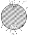
- Figures 1-6 show a preferred embodiment of the superconductive rotor 10 of the present invention. It is noted that existing non-superconducting electrical machines, such as conventional generators, may be retrofitted to have their non-superconductive rotors replaced with the superconductive rotor 10.
- the superconductive rotor 10 includes a generally longitudinally-extending axis 12 and a generally cylindrical-shaped solid core 14 generally coaxially aligned with the axis 12.
- the solid core 14 has high magnetic permeability, is usually made of a ferromagnetic material, and typically is an iron core.
- the solid core 14 has a pair of generally diametrically-opposed and generally longitudinally-extending slots 16 and 18.
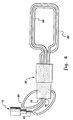
- the superconductive rotor 10 also includes a generally longitudinally-extending, racetrack-shaped superconductive coil 20 and a generally longitudinally-extending, racetrack-shaped thermal shield 22 (both seen in dashed line in Figure 1, seen in solid line in Figures 2 and 3, and seen in detail in Figure 4).
- the superconductive coil 20 surrounds the solid core 14 and has generally straight portions 24 and 26 disposed in the slots 16 and 18.
- the thermal shield 22 generally encloses the superconductive coil 20 and has generally straight portions 28 and 30 disposed in the slots 16 and 18.
- the thermal shield 22 is generally spaced apart from the superconductive coil 20 and from the solid core 14.
- the superconductive rotor 10 further includes a pair of end shafts 32 and 34 attached to the solid core 14 and generally spaced-apart from the thermal shield 22.
- Figure 3 shows end shaft 34 with a notch 36 and shows the thermal shield 22 (and the superconductive coil 20) disposed in the notch 36 spaced-apart from end shaft 34.
- One of the pair of end shafts 32 has a cryogen transfer coupling 38.
- the cryogen transfer coupling 38 would have a stationary segment and a rotating segment as can be appreciated by the artisan.
- the superconductive rotor 10 is a rotor of an electric generator, and the superconductive coil 20 is an electric-generator field coil.
- the end shafts 32 and 34 include bearing journals 40 and 42, and the other of the pair of end shafts 34 has a turbine coupling 44.
- the superconductive coil 20 comprises a stainless-steel support wire 46 co-paired and co-wound with a niobium-tin superconductive wire 48 having a copper stabilizer 50 and all enclosed in a surrounding fiberglass insulating sleeve 52.
- paired wires 46 and 48 are co-wound in as many turns and layers as necessary to create a particular superconductive coil 20.
- the stainless-steel wire 46 provides structural support for the superconductive wire 48 eliminating the need for conventional coil supports. It is noted that the wound superconductive coil 20 is epoxy impregnated for added rigidity and mechanical integrity.
- the superconductive rotor 10 also includes a pair of generally longitudinally-extending first support rods 54 and 56 attached to the solid core 14 proximate one of the slots 16.
- a plurality of longitudinally spaced-apart, rubber-band-shaped, first suspension straps 58 (only one of which is seen in Figure 4) is disposed in the one slot 16.
- Each of the first suspension straps 58 has a center section placed over the thermal shield 22 and has end portions looped around the first support rods 54 and 56.
- the superconductive rotor 10 further includes a pair of generally longitudinally-extending second support rods 60 and 62 disposed in the one slot 16 and attached to the thermal shield 22.
- a multiplicity of longitudinally spaced-apart, rubber-band-shaped, second suspension straps 64 is disposed in the one slot 16.
- Each of the second suspension straps 64 has a center section placed over the superconductive coil 20 and has end portions looped around the second support rods 60 and 62.
- a contoured housing 66 is disposed between the superconductive coil 20 and the center section of the second suspension strap 64 and is attached to the superconductive coil 20. Such contoured housing 66 improves the support for the superconductive coil 20 and increases the strap distance between the superconductive coil 20 and the thermal shield 22 for reduced heat transfer, as can be appreciated by those skilled in the art.
- first support rods and an additional plurality of first suspension straps would be associated with supporting the thermal shield 22 in the other slot 18.
- an additional pair of second support rods and an additional multiplicity of second suspension straps would be associated with supporting the superconductive coil 20 in the other slot 18. It is not necessary to provide such radial support for the thermal shield 22 or the superconductive coil 20 in the notch (not shown in the figures) of the one end shaft 32 or in the notch 36 of the other end shaft 34.
- the superconductive rotor 10 further includes spacer tubes 68 and 70 and spacer plates 72 disposed in the one slot 16, as seen in Figure 4, to provide proper centering of the thermal shield 22 within the one slot 16 and to provide proper centering of the superconductive coil 20 within the thermal shield 22.
- Each of the spacer tubes 68 and 70 has a first end attached to the solid core 14 and has a second end extending into the one slot 16 towards the thermal shield 22.
- Each of the spacer plates 72 has a first portion attached to the thermal shield 22 and has a second portion extending towards the superconductive coil 20.
- the spacer plates may also straddle the contoured housing (such straddling being omitted from the figures for clarity).
- Additional spacer tubes similar to spacer tubes 68 and additional spacer plates (not shown in the figures) similar to spacer plates 72 would provide proper lateral centering of the thermal shield 22 within the notch (not shown in the figures) of the one end shaft 32 and within the notch 36 of the other end shaft 34 and would provide proper lateral centering of the superconductive coil 20 within the thermal shield 22 in the region of the end shafts 32 and 34.
- the cryogen transfer coupling 38 is a gaseous-cryogen transfer coupling 38 having a first inlet 74 and having a second inlet 76.
- a cryocooler coldhead 78 has a cold first stage 80 and a colder second stage 82.
- the first inlet 74 is in fluid communication with a gaseous cryogen (such as gaseous helium) cooled by the cryocooler coldhead first stage 80
- the second inlet 76 is in fluid communication with a gaseous cryogen (such as gaseous helium) cooled by the cryocooler coldhead second stage 82.
- the superconductive rotor 10 additionally includes a generally racetrack-shaped, first cooling tube 84 disposed between the superconductive coil 20 and the thermal shield 22, generally spaced apart from the thermal shield 22, in thermal contact with the superconductive coil 20, and in fluid communication with the second inlet 76 of the gaseous-cryogen transfer coupling 38.
- the superconductive rotor 10 moreover includes a second cooling tube 86 disposed between the thermal shield 22 and the solid core 14, generally spaced apart from the solid core 14, in thermal contact with the thermal shield 22, and in fluid communication with the first inlet 74 of the gaseous-cryogen transfer coupling 38.
- the superconductive rotor 10 has a generally tubular-shaped vacuum envelope 88 attached to the solid core 14, covering the slots 16 and 18, and generally spaced apart from the thermal shield 22.
- a vacuum is drawn on the free volume within the slots and notches to minimize unwanted heat transfer, as can be appreciated by those skilled in the art.
- a conventional aluminum electromagnetic shield 90 surrounds the vacuum envelope 88.
- the solid core 14 is made of iron.
- the superconductive coil 20 is epoxy-impregnated and includes a niobium-tin superconductive wire co-paired and co-wound with a stainless-steel support wire, as previously described.
- the contoured housing 66 is made of aluminum or stainless steel.
- the thermal shield 22 is made of aluminum.
- the first and second cooling tubes 84 and 86 are made of aluminum or stainless steel.
- the first and second support rods 54, 56, 60, and 62 are made of titanium or hardened non-magnetic steel.
- the first and second suspension straps 58 and 64 are made of epoxy-impregnated fiberglass or carbon graphite or other thermal insulating material to minimize heat transfer between their center and end sections.
- the end shafts 32 and 34 are made of high magnetic permeability carbon steel.
- the spacer tubes 68 and 70 are made of fiberglass-epoxy composite, and the spacer plates are made of carbon graphite-epoxy composite to minimize heat transfer between their first and second ends or portions.
- the vacuum envelope 88 is made of stainless steel.
- a conventional Gifford-McMahon cryocooler is used with the coldhead first stage 80 cooling the thermal shield 22 to a temperature of about 40 Kelvin and with the coldhead second stage 82 cooling the superconductive coil 20 to a temperature of about 10 Kelvin.
- the solid core 14 is made of a large center piece which also defines the bottom of the slots 16 and 18, two smaller pieces each defining a side of slot 16, and two other smaller pieces each defining a side of slot 18. Such pieces (not separately shown in the figures) are joined together to define the solid core 14.
- the thermal shield 22 is made of a top piece, a bottom piece, and two side pieces (not separately shown in the figures) which are brought together and welded together in the slots 16 and 18, as can be appreciated by the artisan.
- An engineering analysis of an electric generator superconductive rotor designed in accordance with the principles of the present invention would result in using 200 pounds of superconductive wiring compared with having to use 10,000 pounds of non-superconductive copper wiring in a non-superconductive rotor design or having to use 2000 pounds of superconductive wiring in an air-core, liquid-helium cooled superconductive rotor design. It is noted that the advantage of any superconductive rotor is the elimination of resistive loses and, because of cryogenic cooling, the elimination of thermal cycling problems. Air-core superconductive rotors require large amounts of superconductive wire which adds to the number of coils required, the complexity of the coil supports, and the cost when compared with the superconductive rotor 10 of the present invention.
- Liquid-helium cooled superconductive rotors require continuous reliquefaction of the returned, room-temperature gaseous helium, with such reliquefaction posing significant reliability problems and requiring significant additional energy. Such cooling problems are not present in the superconductive rotor 10 of the present invention.
- an appropriate gaseous-cryogen transfer coupling 38 (including its stationary and rotating segments) is within the skill of the artisan, such detail design not forming a part of the present invention.
- a best mode of supplying cold gaseous cryogen to the superconducting rotor is through a thermally insulated transfer coupling.
- Such a transfer coupling is functionally similar to the liquid-helium transfer couplings known in the prior art, with the following exceptions: 1) the cryogen is single-phase throughout the cooling circuit, and therefore the difficulties associated with two-phase flow (e.g.
- a best mode of supplying the cold gaseous cryogen stream to the superconducting rotor is to use a stationary cryogenic refrigerator (cryocooler) to precool a gas stream from ambient temperature to a cryogenic rotor inlet temperature.
- This precooling is preferably achieved by pressurizing the ambient temperature gas stream sufficiently to overcome the pressure drop of the cryogenic gas circuit, and circulating the gas in such a manner as to precool the gas using the cooling available from the cold gas returning from the rotor.
- the maximum thermodynamic efficiency is achieved, and the cooling requirement for the stationary refrigerator is minimized.
- This best mode differs from the practices known in the prior art as follows: 1) the gaseous stream may be circulated at a low pressure, without having to expand the gas from high pressures to achieve liquefaction; 2) joule-thompson expansion valves are eliminated from the circuit, thereby improving the reliability of the system; and 3) the low-pressure gaseous cryogen cooling circuit can be kept independent from the refrigerator gas circuit, thereby permitting redundancy and serviceability of the refrigerator components independent of the low-pressure circuit.
Landscapes
- Engineering & Computer Science (AREA)
- Power Engineering (AREA)
- Superconductive Dynamoelectric Machines (AREA)
Applications Claiming Priority (2)
| Application Number | Priority Date | Filing Date | Title |
|---|---|---|---|
| US08/267,625 US5548168A (en) | 1994-06-29 | 1994-06-29 | Superconducting rotor for an electrical machine |
| US267625 | 1994-06-29 |
Publications (3)
| Publication Number | Publication Date |
|---|---|
| EP0690550A2 true EP0690550A2 (de) | 1996-01-03 |
| EP0690550A3 EP0690550A3 (de) | 1996-03-27 |
| EP0690550B1 EP0690550B1 (de) | 1997-11-26 |
Family
ID=23019550
Family Applications (1)
| Application Number | Title | Priority Date | Filing Date |
|---|---|---|---|
| EP95304459A Expired - Lifetime EP0690550B1 (de) | 1994-06-29 | 1995-06-26 | Supraleitender Rotor für eine elektrische Maschine |
Country Status (4)
| Country | Link |
|---|---|
| US (1) | US5548168A (de) |
| EP (1) | EP0690550B1 (de) |
| JP (1) | JP3727977B2 (de) |
| DE (1) | DE69501099T2 (de) |
Cited By (14)
| Publication number | Priority date | Publication date | Assignee | Title |
|---|---|---|---|---|
| US5672921A (en) * | 1995-03-13 | 1997-09-30 | General Electric Company | Superconducting field winding assemblage for an electrical machine |
| EP0805545A1 (de) * | 1996-05-01 | 1997-11-05 | General Electric Company | Zusammenstellung einer supraleitenden Feldwicklung für eine elektrische Maschine |
| EP0805546A1 (de) * | 1996-05-01 | 1997-11-05 | General Electric Company | Trägerstruktur für eine supraleitende Wicklung |
| EP0825706A1 (de) * | 1996-08-23 | 1998-02-25 | General Electric Company | Anordnung zum Kühlen einer supraleitenden Wicklung |
| EP1203437A4 (de) * | 1999-08-10 | 2002-10-23 | American Superconductor Corp | Supraleitender elektromotor |
| EP1261105A2 (de) * | 2001-05-15 | 2002-11-27 | General Electric Company | Rotorspulenunterstützung für Hochtemperatursupraleiter mit Verspannungsstäben und -bolzen und Montierverfahren |
| WO2003047963A1 (de) * | 2001-11-30 | 2003-06-12 | Siemens Aktiengesellschaft | Schiffsantrieb |
| WO2004068682A1 (de) * | 2003-01-28 | 2004-08-12 | Siemens Aktiegesellschaft | Maschine mit einem rotor und einer supraleitenden rotorwicklung |
| EP1289104A3 (de) * | 2001-08-24 | 2004-09-22 | General Electric Company | Mehrteiliger Rotorkern für Hochtemperatur- supraleitende Rotorwicklungen |
| EP1420508A3 (de) * | 2002-11-13 | 2006-10-04 | General Electric Company | Kälteumgebungseinheit für mehrpolige Läufer mit supraleitenden Erregerwicklungen |
| US8319390B2 (en) | 2009-09-29 | 2012-11-27 | American Superconductor Corporation | Generator with ferromagnetic teeth |
| CZ303903B6 (cs) * | 2001-08-15 | 2013-06-19 | General Electric Company | Supravodivý elektromagnetický stroj a zpusob jeho chlazení |
| WO2014022000A3 (en) * | 2012-07-02 | 2014-05-30 | Siemens Energy, Inc. | Apparatus to support superconducting windings in a rotor of an electromotive machine |
| KR20220031080A (ko) * | 2019-07-09 | 2022-03-11 | 제네럴 일렉트릭 컴퍼니 | 자성 재료로 형성된 진공 용기를 포함하는 초전도 발전기 |
Families Citing this family (43)
| Publication number | Priority date | Publication date | Assignee | Title |
|---|---|---|---|---|
| US5777420A (en) * | 1996-07-16 | 1998-07-07 | American Superconductor Corporation | Superconducting synchronous motor construction |
| DE19751055A1 (de) * | 1997-11-18 | 1999-05-20 | Abb Patent Gmbh | Gasgekühlter Turbogenerator |
| US6376943B1 (en) * | 1998-08-26 | 2002-04-23 | American Superconductor Corporation | Superconductor rotor cooling system |
| US6489701B1 (en) * | 1999-10-12 | 2002-12-03 | American Superconductor Corporation | Superconducting rotating machines |
| EP1107430A3 (de) * | 1999-12-06 | 2003-10-29 | General Electric Company | Aufweitbare flache Wicklung für das Läuferfeldsystem von elektrischen Maschinen |
| US6693504B1 (en) * | 2000-01-11 | 2004-02-17 | American Superconductor Corporation | Internal support for superconductor windings |
| AU2001224247A1 (en) * | 2000-01-11 | 2001-07-24 | American Superconductor Corporation | Segmented rotor assembly for superconducting rotating machines |
| US6460346B1 (en) * | 2000-08-30 | 2002-10-08 | General Electric Company | Method and system for identifying malfunctioning combustion chambers in a gas turbine |
| US6590308B2 (en) * | 2001-05-15 | 2003-07-08 | General Electric Company | High power density super-conducting electric machine |
| US6553773B2 (en) | 2001-05-15 | 2003-04-29 | General Electric Company | Cryogenic cooling system for rotor having a high temperature super-conducting field winding |
| US6590305B2 (en) | 2001-05-15 | 2003-07-08 | General Electric Company | High temperature super-conducting synchronous rotor having an electromagnetic shield and method for assembly |
| US6803684B2 (en) | 2001-05-15 | 2004-10-12 | General Electric Company | Super-conducting synchronous machine having rotor and a plurality of super-conducting field coil windings |
| US6570292B2 (en) * | 2001-05-15 | 2003-05-27 | General Electric Company | High temperature super-conducting rotor coil support with split coil housing and assembly method |
| US6577028B2 (en) | 2001-05-15 | 2003-06-10 | General Electric Company | High temperature superconducting rotor power leads |
| US6922885B2 (en) | 2001-05-15 | 2005-08-02 | General Electric Company | High temperature superconducting racetrack coil |
| US6727633B2 (en) * | 2001-05-15 | 2004-04-27 | General Electric Company | High temperature super-conducting synchronous rotor coil support with tension rods and method for assembly of the coil support |
| US6617714B2 (en) | 2001-05-15 | 2003-09-09 | General Electric Company | High temperature super-conducting coils supported by an iron core rotor |
| US6608409B2 (en) * | 2001-05-15 | 2003-08-19 | General Electric Company | High temperature super-conducting rotor having a vacuum vessel and electromagnetic shield and an assembly method |
| US6787967B2 (en) | 2001-05-15 | 2004-09-07 | General Electric Company | High temperature super-conducting rotor coil support and coil support method |
| US6617738B2 (en) | 2001-06-01 | 2003-09-09 | Charles B Dickinson | Electrical power generation system utilizing an electrically superconductive coil |
| US6438969B1 (en) | 2001-07-12 | 2002-08-27 | General Electric Company | Cryogenic cooling refrigeration system for rotor having a high temperature super-conducting field winding and method |
| US6605886B2 (en) * | 2001-07-31 | 2003-08-12 | General Electric Company | High temperature superconductor synchronous rotor coil support insulator |
| US6882068B2 (en) * | 2002-10-08 | 2005-04-19 | General Electric Company | Forced air stator ventilation system and stator ventilation method for superconducting synchronous machine |
| US6708503B1 (en) | 2002-12-27 | 2004-03-23 | General Electric Company | Vacuum retention method and superconducting machine with vacuum retention |
| US6725683B1 (en) | 2003-03-12 | 2004-04-27 | General Electric Company | Cryogenic cooling system for rotor having a high temperature super-conducting field winding |
| US6897577B2 (en) * | 2003-07-14 | 2005-05-24 | General Electric Company | Methods and system for power generation |
| US7003977B2 (en) * | 2003-07-18 | 2006-02-28 | General Electric Company | Cryogenic cooling system and method with cold storage device |
| US6930471B2 (en) * | 2003-10-06 | 2005-08-16 | General Electric Company | Hybrid synchronous/induction generator power plant |
| US7053509B2 (en) * | 2004-03-30 | 2006-05-30 | General Electric Company | Quench monitoring and control system and method of operating same |
| DE102004039855A1 (de) * | 2004-08-17 | 2006-03-09 | Siemens Ag | Maschine mit einer Erregerwicklung aus Hoch-Tc-Supraleitern in einer Halteeinrichtung |
| JP5481070B2 (ja) | 2006-01-19 | 2014-04-23 | マサチューセッツ インスティテュート オブ テクノロジー | 粒子加速のための磁場生成方法、磁石構造体及びその製造方法 |
| DE102006027219A1 (de) | 2006-06-12 | 2007-12-20 | Siemens Ag | Maschine mit ungekühltem Rotorkörper und gekühlter Rotorwicklung sowie zugeordneter Halte- und/oder Abstützeinrichtung |
| US7633192B2 (en) * | 2006-09-28 | 2009-12-15 | Siemens Energy, Inc. | Superconducting coil support structures |
| KR100817225B1 (ko) * | 2006-11-15 | 2008-03-27 | 두산중공업 주식회사 | 초전도 회전기기의 전류리드 냉각 및 고정장치 |
| US20090229291A1 (en) * | 2008-03-11 | 2009-09-17 | American Superconductor Corporation | Cooling System in a Rotating Reference Frame |
| JP5496573B2 (ja) * | 2009-08-11 | 2014-05-21 | 川崎重工業株式会社 | ロータコア及び該ロータコアの冷却方法、該ロータコアを具備する超電導回転機 |
| KR101372291B1 (ko) | 2010-11-08 | 2014-03-11 | 가와사끼 쥬고교 가부시끼 가이샤 | 로터 코어 및 이 로터 코어를 구비하는 초전도 회전기 |
| US8664809B2 (en) * | 2011-03-15 | 2014-03-04 | Siemens Energy, Inc. | Apparatus to support superconducting windings in a rotor of an electromotive machine |
| US9431864B2 (en) * | 2011-03-15 | 2016-08-30 | Siemens Energy, Inc. | Apparatus to support superconducting windings in a rotor of an electromotive machine |
| US9559569B2 (en) | 2012-02-13 | 2017-01-31 | Ge Aviation Systems Llc | Arrangement for cooling an electric machine with a layer of thermally conducting and electrically insulating material |
| DE102014211029A1 (de) | 2014-06-10 | 2015-12-17 | Siemens Aktiengesellschaft | Elektrische Maschine für hohe Drehzahlen |
| EP3609060A1 (de) * | 2018-08-08 | 2020-02-12 | Siemens Gamesa Renewable Energy A/S | Generator mit supraleitenden spulenwicklungen |
| CN113316886B (zh) | 2018-11-21 | 2024-08-23 | 通用电气可再生能源西班牙有限公司 | 由风力涡轮驱动的超导发电机 |
Family Cites Families (17)
| Publication number | Priority date | Publication date | Assignee | Title |
|---|---|---|---|---|
| DE1665555C3 (de) * | 1966-02-18 | 1975-02-27 | Siemens Ag, 1000 Berlin Und 8000 Muenchen | Supraleiter mit einer Isolation an der Oberfläche |
| US4155019A (en) * | 1973-06-27 | 1979-05-15 | Kraftwerk Union Aktiengesellschaft | Coupling assembly for mutually coupling a generator rotor having a superconductive exciter winding and a shaft carrying exciter current leads |
| US3891875A (en) * | 1973-10-16 | 1975-06-24 | Gen Electric | Superconducting rotor |
| US3991333A (en) * | 1975-08-20 | 1976-11-09 | General Electric Company | Winding support structure for superconducting rotor |
| US4048529A (en) * | 1975-11-26 | 1977-09-13 | Gen Electric | Flow control device for superconductive rotor refrigerant |
| US4082967A (en) * | 1976-03-31 | 1978-04-04 | General Electric Company | Uniformly-cooled superconducting rotor |
| US4176291A (en) * | 1977-05-27 | 1979-11-27 | Electric Power Research Institute, Inc. | Stored field superconducting electrical machine and method |
| US4176292A (en) * | 1977-09-02 | 1979-11-27 | Electric Power Research Institute, Inc. | Auxiliary field winding for a superconductive alternating current electrical machine and method of exciting same |
| US4278905A (en) * | 1977-12-27 | 1981-07-14 | Electric Power Research Institute | Apparatus for supporting a stator winding in a superconductive generator |
| US4251745A (en) * | 1978-01-25 | 1981-02-17 | Bbc Brown, Boveri & Company, Limited | Method and apparatus for cooling superconductive windings of electric machines |
| US4291997A (en) * | 1978-02-17 | 1981-09-29 | General Electric Company | Flexible support for superconducting machine rotor |
| US4279944A (en) * | 1978-12-26 | 1981-07-21 | General Electric Company | Epoxy impregnated ventilated winding |
| DE3613039A1 (de) * | 1986-03-06 | 1987-09-10 | Kraftwerk Union Ag | Laeufer einer dynamoelektrischen maschine, insbesondere turbogenerator-laeufer mit supraleitender erregerwicklung, und verfahren zu seiner herstellung |
| US4924198A (en) * | 1988-07-05 | 1990-05-08 | General Electric Company | Superconductive magnetic resonance magnet without cryogens |
| US4986078A (en) * | 1989-08-17 | 1991-01-22 | General Electric Company | Refrigerated MR magnet support system |
| US5034713A (en) * | 1990-04-06 | 1991-07-23 | General Electric Company | Radial support system for a MR magnet |
| US5381122A (en) * | 1994-01-14 | 1995-01-10 | General Electric Company | Open MRI magnet having a support structure |
-
1994
- 1994-06-29 US US08/267,625 patent/US5548168A/en not_active Expired - Fee Related
-
1995
- 1995-06-23 JP JP15657295A patent/JP3727977B2/ja not_active Expired - Fee Related
- 1995-06-26 EP EP95304459A patent/EP0690550B1/de not_active Expired - Lifetime
- 1995-06-26 DE DE69501099T patent/DE69501099T2/de not_active Expired - Lifetime
Non-Patent Citations (1)
| Title |
|---|
| None |
Cited By (20)
| Publication number | Priority date | Publication date | Assignee | Title |
|---|---|---|---|---|
| US5672921A (en) * | 1995-03-13 | 1997-09-30 | General Electric Company | Superconducting field winding assemblage for an electrical machine |
| EP0805545A1 (de) * | 1996-05-01 | 1997-11-05 | General Electric Company | Zusammenstellung einer supraleitenden Feldwicklung für eine elektrische Maschine |
| EP0805546A1 (de) * | 1996-05-01 | 1997-11-05 | General Electric Company | Trägerstruktur für eine supraleitende Wicklung |
| EP0825706A1 (de) * | 1996-08-23 | 1998-02-25 | General Electric Company | Anordnung zum Kühlen einer supraleitenden Wicklung |
| US7453174B1 (en) | 1999-08-10 | 2008-11-18 | American Superconductor Corporation | Superconducting electric motor |
| EP1203437A4 (de) * | 1999-08-10 | 2002-10-23 | American Superconductor Corp | Supraleitender elektromotor |
| EP1261105A2 (de) * | 2001-05-15 | 2002-11-27 | General Electric Company | Rotorspulenunterstützung für Hochtemperatursupraleiter mit Verspannungsstäben und -bolzen und Montierverfahren |
| CZ303903B6 (cs) * | 2001-08-15 | 2013-06-19 | General Electric Company | Supravodivý elektromagnetický stroj a zpusob jeho chlazení |
| EP1289104A3 (de) * | 2001-08-24 | 2004-09-22 | General Electric Company | Mehrteiliger Rotorkern für Hochtemperatur- supraleitende Rotorwicklungen |
| CZ302241B6 (cs) * | 2001-08-24 | 2011-01-05 | General Electric Company | Rotor synchronního stroje s vysokoteplotní supravodivou synchronní rotorovou cívkou s vícedílným jádrem rotoru a zpusob montáže jádra rotoru |
| WO2003047963A1 (de) * | 2001-11-30 | 2003-06-12 | Siemens Aktiengesellschaft | Schiffsantrieb |
| EP1420508A3 (de) * | 2002-11-13 | 2006-10-04 | General Electric Company | Kälteumgebungseinheit für mehrpolige Läufer mit supraleitenden Erregerwicklungen |
| CN1745512B (zh) * | 2003-01-28 | 2012-04-04 | 西门子公司 | 具有转子和超导转子绕组的机器 |
| WO2004068682A1 (de) * | 2003-01-28 | 2004-08-12 | Siemens Aktiegesellschaft | Maschine mit einem rotor und einer supraleitenden rotorwicklung |
| US8319390B2 (en) | 2009-09-29 | 2012-11-27 | American Superconductor Corporation | Generator with ferromagnetic teeth |
| WO2014022000A3 (en) * | 2012-07-02 | 2014-05-30 | Siemens Energy, Inc. | Apparatus to support superconducting windings in a rotor of an electromotive machine |
| JP2015522237A (ja) * | 2012-07-02 | 2015-08-03 | シーメンス エナジー インコーポレイテッド | 電動機械のロータの内部において超電導巻線を支持するための装置 |
| US9293959B2 (en) | 2012-07-02 | 2016-03-22 | Siemens Energy, Inc. | Apparatus to support superconducting windings in a rotor of an electomotive machine |
| CN104508961B (zh) * | 2012-07-02 | 2019-05-10 | 西门子能量股份有限公司 | 支撑电动机的转子中的超导绕组的设备 |
| KR20220031080A (ko) * | 2019-07-09 | 2022-03-11 | 제네럴 일렉트릭 컴퍼니 | 자성 재료로 형성된 진공 용기를 포함하는 초전도 발전기 |
Also Published As
| Publication number | Publication date |
|---|---|
| US5548168A (en) | 1996-08-20 |
| JP3727977B2 (ja) | 2005-12-21 |
| DE69501099D1 (de) | 1998-01-08 |
| EP0690550B1 (de) | 1997-11-26 |
| JPH08168235A (ja) | 1996-06-25 |
| EP0690550A3 (de) | 1996-03-27 |
| DE69501099T2 (de) | 1998-06-04 |
Similar Documents
| Publication | Publication Date | Title |
|---|---|---|
| EP0690550B1 (de) | Supraleitender Rotor für eine elektrische Maschine | |
| US6553773B2 (en) | Cryogenic cooling system for rotor having a high temperature super-conducting field winding | |
| US6438969B1 (en) | Cryogenic cooling refrigeration system for rotor having a high temperature super-conducting field winding and method | |
| US5672921A (en) | Superconducting field winding assemblage for an electrical machine | |
| US6605886B2 (en) | High temperature superconductor synchronous rotor coil support insulator | |
| JP4247273B2 (ja) | 回転子と超伝導性の回転子巻線とを備えた機械 | |
| CA2384482C (en) | High temperature super-conducting synchronous rotor coil support with tension rods and method for assembly of the coil support | |
| EP0805545B1 (de) | Zusammenstellung einer supraleitenden Feldwicklung für eine elektrische Maschine | |
| KR100902693B1 (ko) | 동기 장치용 로터 및 고온 초전도 로터 조립 방법 | |
| US6590308B2 (en) | High power density super-conducting electric machine | |
| US6787967B2 (en) | High temperature super-conducting rotor coil support and coil support method | |
| Johnson et al. | Superconducting field coil for high-voltage homopolar generator |
Legal Events
| Date | Code | Title | Description |
|---|---|---|---|
| PUAI | Public reference made under article 153(3) epc to a published international application that has entered the european phase |
Free format text: ORIGINAL CODE: 0009012 |
|
| AK | Designated contracting states |
Kind code of ref document: A2 Designated state(s): DE FR GB |
|
| PUAL | Search report despatched |
Free format text: ORIGINAL CODE: 0009013 |
|
| AK | Designated contracting states |
Kind code of ref document: A3 Designated state(s): DE FR GB |
|
| 17P | Request for examination filed |
Effective date: 19960927 |
|
| GRAG | Despatch of communication of intention to grant |
Free format text: ORIGINAL CODE: EPIDOS AGRA |
|
| 17Q | First examination report despatched |
Effective date: 19970307 |
|
| GRAH | Despatch of communication of intention to grant a patent |
Free format text: ORIGINAL CODE: EPIDOS IGRA |
|
| GRAH | Despatch of communication of intention to grant a patent |
Free format text: ORIGINAL CODE: EPIDOS IGRA |
|
| GRAA | (expected) grant |
Free format text: ORIGINAL CODE: 0009210 |
|
| AK | Designated contracting states |
Kind code of ref document: B1 Designated state(s): DE FR GB |
|
| ET | Fr: translation filed | ||
| REF | Corresponds to: |
Ref document number: 69501099 Country of ref document: DE Date of ref document: 19980108 |
|
| PLBE | No opposition filed within time limit |
Free format text: ORIGINAL CODE: 0009261 |
|
| STAA | Information on the status of an ep patent application or granted ep patent |
Free format text: STATUS: NO OPPOSITION FILED WITHIN TIME LIMIT |
|
| 26N | No opposition filed | ||
| REG | Reference to a national code |
Ref country code: GB Ref legal event code: IF02 |
|
| PGFP | Annual fee paid to national office [announced via postgrant information from national office to epo] |
Ref country code: GB Payment date: 20130627 Year of fee payment: 19 Ref country code: DE Payment date: 20130627 Year of fee payment: 19 |
|
| PGFP | Annual fee paid to national office [announced via postgrant information from national office to epo] |
Ref country code: FR Payment date: 20130702 Year of fee payment: 19 |
|
| REG | Reference to a national code |
Ref country code: DE Ref legal event code: R119 Ref document number: 69501099 Country of ref document: DE |
|
| GBPC | Gb: european patent ceased through non-payment of renewal fee |
Effective date: 20140626 |
|
| REG | Reference to a national code |
Ref country code: DE Ref legal event code: R119 Ref document number: 69501099 Country of ref document: DE Effective date: 20150101 |
|
| REG | Reference to a national code |
Ref country code: FR Ref legal event code: ST Effective date: 20150227 |
|
| PG25 | Lapsed in a contracting state [announced via postgrant information from national office to epo] |
Ref country code: DE Free format text: LAPSE BECAUSE OF NON-PAYMENT OF DUE FEES Effective date: 20150101 |
|
| PG25 | Lapsed in a contracting state [announced via postgrant information from national office to epo] |
Ref country code: GB Free format text: LAPSE BECAUSE OF NON-PAYMENT OF DUE FEES Effective date: 20140626 Ref country code: FR Free format text: LAPSE BECAUSE OF NON-PAYMENT OF DUE FEES Effective date: 20140630 |