EP0690567A2 - Procédé et montage pour la détermination automatique de la fréquence de l'oscillateur du convertisseur de fréquence, agence dans la partie extérieux d'un montage de réception pour satellite - Google Patents
Procédé et montage pour la détermination automatique de la fréquence de l'oscillateur du convertisseur de fréquence, agence dans la partie extérieux d'un montage de réception pour satellite Download PDFInfo
- Publication number
- EP0690567A2 EP0690567A2 EP95107881A EP95107881A EP0690567A2 EP 0690567 A2 EP0690567 A2 EP 0690567A2 EP 95107881 A EP95107881 A EP 95107881A EP 95107881 A EP95107881 A EP 95107881A EP 0690567 A2 EP0690567 A2 EP 0690567A2
- Authority
- EP
- European Patent Office
- Prior art keywords
- satellite
- predetermined
- frequency
- oscillator
- reception
- Prior art date
- Legal status (The legal status is an assumption and is not a legal conclusion. Google has not performed a legal analysis and makes no representation as to the accuracy of the status listed.)
- Granted
Links
Images
Classifications
-
- H—ELECTRICITY
- H03—ELECTRONIC CIRCUITRY
- H03J—TUNING RESONANT CIRCUITS; SELECTING RESONANT CIRCUITS
- H03J1/00—Details of adjusting, driving, indicating, or mechanical control arrangements for resonant circuits in general
- H03J1/0008—Details of adjusting, driving, indicating, or mechanical control arrangements for resonant circuits in general using a central processing unit, e.g. a microprocessor
- H03J1/0058—Details of adjusting, driving, indicating, or mechanical control arrangements for resonant circuits in general using a central processing unit, e.g. a microprocessor provided with channel identification means
- H03J1/0066—Details of adjusting, driving, indicating, or mechanical control arrangements for resonant circuits in general using a central processing unit, e.g. a microprocessor provided with channel identification means with means for analysing the received signal strength
- H03J1/0075—Details of adjusting, driving, indicating, or mechanical control arrangements for resonant circuits in general using a central processing unit, e.g. a microprocessor provided with channel identification means with means for analysing the received signal strength where the receiving frequencies of the stations are stored in a permanent memory, e.g. ROM
Definitions
- the invention relates to a method and an arrangement for the automatic detection of the oscillator frequency of a frequency converter of a satellite reception system.
- a television receiver which can be tuned either to antenna channels or cable channels.
- the tuner when the user presses the button for automatic station programming to store the receivable stations, the tuner is first caused to work in the cable tuning mode, the tuning being carried out successively on the channels of a predetermined test group of cable channels. If there are valid signals for a predetermined number of channels, the receiver is held in the cable mode and an auto-programming process is initiated in order to program the channel lists of a memory with all receivable cable channels. If, on the other hand, the predetermined reception criterion is not met in the predetermined test group, the receiver is caused to switch to the tuning mode for antenna reception.
- a method for tuning an AM receiver is known from DE-A1 32 42 430, in which an automatic tuning to transmitters is to take place, the transmission frequencies of which have different frequency grids.
- the level of the received signal is measured when a frequency is received in a frequency grid and compared with the level of the received signal with a frequency of the second frequency grid.
- the receiver is then tuned to the frequency that delivers the higher signal level.
- a satellite receiver has the task of converting satellite television signals provided by the external unit of a satellite reception system, which are in a frequency range from 910 to 2050 MHz, into a form which any conventional television set and any conventional video recorder can process, for example a CVBS signal, which is provided at a Euro-AV socket of the satellite receiver, or in a signal lying in the UHF range, which is at an antenna socket of the Satellite receiver is issued. Furthermore, it is also possible to install the satellite receiver in a common housing with a television receiver or a video recorder.
- the object of the invention is to show a way in which the adaptation of a satellite receiver to an external unit present at the receiving location can be simplified.
- the advantages of the invention are, in particular, that the setting of the necessary oscillator frequency of the frequency converter takes place automatically with the aid of reception parameters stored in a memory and various oscillator frequencies in question, so that the user does not have to know the oscillator frequency required in each case. Furthermore, the automatic setting of the necessary oscillator frequency generally avoids any operating errors which can occur in known satellite receivers when the oscillator frequency is entered manually.
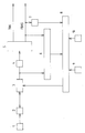
- the outdoor unit with a satellite antenna 1 and a low-noise frequency converter unit 2 (LNC) and an indoor unit (satellite receiver) with a satellite tuner 3, a mixer 4, a signal processing circuit 5, a quality evaluation circuit 6, a teletext signal evaluation circuit 7, a microcomputer 8, a first storage unit 9 and a second storage unit 10.
- LNC low-noise frequency converter unit 2
- the satellite antenna 1 and the low-noise frequency converter unit 2 are permanently installed at the receiving location.
- the satellite antenna is oriented in such a way that it can optimally receive the satellite television signals emitted by a satellite, for example signals from the satellite ASTRA.
- the low-noise frequency converter unit 2 consists of a low-noise preamplifier, an image frequency filter, a mixer, an oscillator for generating mixed signals and a selective amplifier
- the satellite receiver is a television receiver with an integrated satellite receiver, a video recorder with an integrated satellite receiver, a satellite receiver as a stand-alone device, or a satellite receiver that is intended for retrofitting a television receiver or video recorder.
- the microcomputer 8 can be a microcomputer which is part of the satellite reception part or the microcomputer of the television receiver or video recorder if a television receiver or video recorder with an integrated satellite reception part is present.
- the storage units 9 and 10 of the satellite receiver which are drawn as separate memories for illustration purposes, data are already stored at the factory in order to make it easier for the user to start up the satellite receiver.
- a plurality of predetermined oscillator frequencies which are suitable for the low-noise frequency converter unit are stored in the memory unit 9, for example 9.75 GHz, 10 GHz, 10.75 GHz and 11 GHz.
- oscillator frequencies can also be stored in the memory unit 9, which have a predetermined frequency spacing from one another and cover a predetermined frequency interval.
- the frequency interval can range from 9 to 11 GHz and the frequency spacing can be 10 MHz.
- the satellite parameters required for programming the satellite receiver for a plurality of satellite transmitters are stored. Specifically, these are the frequency or channel number, the direction of polarization, the video hub, the video modulation, the IF bandwidth, the audio frequencies, the audio mode and the station name.
- the microcomputer 8 is programmed in such a way that, after entering an initialization command or automatically when the satellite receiver is started for the first time, it selects a first satellite transmitter whose parameters are stored in the memory unit 10. Furthermore, the microcomputer 8 reads out a predetermined oscillator frequency from the memory unit 9. The parameters mentioned and the oscillator frequency, which influence the signal processing in the satellite tuner 3, are fed to the satellite tuner 3. The information about the polarity is passed on from the satellite tuner to the outdoor unit in order to trigger a polarizer switch there if necessary.
- the output signal of the satellite tuner 3 is passed in a generally known manner via a mixer 4 and a signal processing circuit 5.
- the sound signal and a composite signal are available, which are forwarded, for example, to a Euro-AV socket (not shown) of the satellite receiver.
- the output signal of the satellite tuner 3 is fed to a circuit 6 for quality evaluation. In this circuit it is checked whether the level of the output signal of the satellite tuner 3 is greater than a predetermined reference value or not.
- the FBAS signal present at the output of the signal processing circuit 5 can also be supplied to the circuit 6 for quality evaluation.
- the quality assessment can also be carried out by evaluating the bit error rate of a teletext signal transmitted in the blanking intervals of the composite signal.
- the CVBS signal available at the output of the signal processing circuit 5 is also conducted via a teletext signal evaluation circuit 7, by means of which signals are extracted from the teletext signal that correspond to the station name. These signals are fed to the microcomputer 8 and compared there with signals which also correspond to the transmitter name and are taken from the memory unit 10.
- the first predetermined oscillator frequency is recognized as the correct one and transferred to a memory (not shown) so that it is available for the further operation of the satellite receiver.
- the microcomputer 8 reads a second of the predetermined oscillator frequencies from the memory unit 9 in order to carry out the method described above using the predetermined second oscillator frequency to repeat for the 5 selected satellite channels. If the second predetermined oscillator frequency is recognized as the correct one, it is transferred to the named memory. If this is not the case, then the method is repeated using the further predetermined oscillator frequencies until the correct oscillator frequency has been found or until the tests have been carried out for all the predetermined oscillator frequencies. in the the latter case, after the end of analysis by means of an OSD block (o n s creen- d isplay) has a corresponding plain-text message to be displayed on a screen.
- OSD block o n s creen- d isplay
- the user does not need to know the oscillator frequency used in the frequency converter of the outdoor unit and also does not have to enter it using the keyboard of the satellite receiver. For inexperienced users in particular, this means a significant simplification when commissioning the satellite receiver.
- the above-described extraction of the station name by means of the teletext evaluation circuit 7 can be used in the later operation of the satellite receiver to recognize whether the station assignment has changed or not. If a change in the station allocation is detected, the satellite station memory can be updated automatically and the user can be informed of this by means of a plain text display on the screen.
Landscapes
- Engineering & Computer Science (AREA)
- Computer Hardware Design (AREA)
- Microelectronics & Electronic Packaging (AREA)
- Circuits Of Receivers In General (AREA)
- Radio Relay Systems (AREA)
- Two-Way Televisions, Distribution Of Moving Picture Or The Like (AREA)
- Input Circuits Of Receivers And Coupling Of Receivers And Audio Equipment (AREA)
Applications Claiming Priority (2)
| Application Number | Priority Date | Filing Date | Title |
|---|---|---|---|
| DE4422908 | 1994-06-30 | ||
| DE4422908A DE4422908C1 (de) | 1994-06-30 | 1994-06-30 | Verfahren und Anordnung zur automatischen Erkennung der Oszillatorfrequenz eines in der Außeneinheit einer Satelliten-Empfangsanlage angeordneten Frequenzumsetzers |
Publications (3)
| Publication Number | Publication Date |
|---|---|
| EP0690567A2 true EP0690567A2 (fr) | 1996-01-03 |
| EP0690567A3 EP0690567A3 (fr) | 1996-10-23 |
| EP0690567B1 EP0690567B1 (fr) | 2004-12-15 |
Family
ID=6521901
Family Applications (1)
| Application Number | Title | Priority Date | Filing Date |
|---|---|---|---|
| EP95107881A Expired - Lifetime EP0690567B1 (fr) | 1994-06-30 | 1995-05-20 | Procédé et montage pour la détermination automatique de la fréquence de l'oscillateur du convertisseur de fréquence, agence dans la partie extérieux d'un montage de réception pour satellite |
Country Status (4)
| Country | Link |
|---|---|
| EP (1) | EP0690567B1 (fr) |
| AT (1) | ATE285138T1 (fr) |
| DE (2) | DE4422908C1 (fr) |
| ES (1) | ES2233934T3 (fr) |
Families Citing this family (2)
| Publication number | Priority date | Publication date | Assignee | Title |
|---|---|---|---|---|
| DE19815953C1 (de) * | 1998-04-09 | 1999-09-23 | Grundig Ag | Verfahren und Vorrichtung zur Kompensation von Frequenzabweichungen beim Empfang von Satelliten-Rundfunksignalen mittels einer Satellitenempfangsanlage |
| DE19833309B4 (de) * | 1998-07-24 | 2004-11-25 | Grundig Ag | Fernsehempfänger mit Onscreen-Display |
Citations (3)
| Publication number | Priority date | Publication date | Assignee | Title |
|---|---|---|---|---|
| DE3242430A1 (de) | 1981-11-18 | 1983-05-26 | Pioneer Electronic Corp., Tokyo | Verfahren und vorrichtung zum abstimmen eines am-empfaengers |
| DE3801524C2 (fr) | 1987-01-21 | 1990-10-18 | Rca Licensing Corp., Princeton, N.J., Us | |
| EP0483463A2 (fr) | 1990-10-30 | 1992-05-06 | GRUNDIG E.M.V. Elektro-Mechanische Versuchsanstalt Max Grundig GmbH & Co. KG | Dispositif de programmation des chaînes pour une réception par satellite |
Family Cites Families (2)
| Publication number | Priority date | Publication date | Assignee | Title |
|---|---|---|---|---|
| GB9103713D0 (en) * | 1991-02-22 | 1991-04-10 | Amstrad Plc | Improvements relating to television systems |
| DE4241599C2 (de) * | 1992-12-10 | 1995-03-23 | Grundig Emv | Fernsehempfänger zur Wiedergabe von terrestrisch und über Satellit übertragenen Fernsehsignalen |
-
1994
- 1994-06-30 DE DE4422908A patent/DE4422908C1/de not_active Expired - Fee Related
-
1995
- 1995-05-20 AT AT95107881T patent/ATE285138T1/de not_active IP Right Cessation
- 1995-05-20 DE DE59510978T patent/DE59510978D1/de not_active Expired - Lifetime
- 1995-05-20 ES ES95107881T patent/ES2233934T3/es not_active Expired - Lifetime
- 1995-05-20 EP EP95107881A patent/EP0690567B1/fr not_active Expired - Lifetime
Patent Citations (3)
| Publication number | Priority date | Publication date | Assignee | Title |
|---|---|---|---|---|
| DE3242430A1 (de) | 1981-11-18 | 1983-05-26 | Pioneer Electronic Corp., Tokyo | Verfahren und vorrichtung zum abstimmen eines am-empfaengers |
| DE3801524C2 (fr) | 1987-01-21 | 1990-10-18 | Rca Licensing Corp., Princeton, N.J., Us | |
| EP0483463A2 (fr) | 1990-10-30 | 1992-05-06 | GRUNDIG E.M.V. Elektro-Mechanische Versuchsanstalt Max Grundig GmbH & Co. KG | Dispositif de programmation des chaînes pour une réception par satellite |
Also Published As
| Publication number | Publication date |
|---|---|
| ES2233934T3 (es) | 2005-06-16 |
| EP0690567A3 (fr) | 1996-10-23 |
| ATE285138T1 (de) | 2005-01-15 |
| EP0690567B1 (fr) | 2004-12-15 |
| DE4422908C1 (de) | 1995-11-02 |
| DE59510978D1 (de) | 2005-01-20 |
Similar Documents
| Publication | Publication Date | Title |
|---|---|---|
| EP0309878B1 (fr) | Procédé et/ou dispositif de programmation pour appareils audio ou vidéo | |
| DE3889272T2 (de) | Verfahren und Gerät zur Ermittlung des Empfangskanals eines Empfängers. | |
| DE69102718T2 (de) | Apparat zur Verarbeitung eines Videosignals. | |
| DE4103062C2 (de) | Rundfunkempfänger | |
| DE4207766A1 (de) | Kanalauswahlverfahren fuer rundfunkprogramme gleicher kategorie | |
| DE19548957C2 (de) | Automatisches Kanalsuchverfahren für einen Fernsehempfänger | |
| EP0716792A1 (fr) | Procede et dispositif de detection de scenes video indesirables | |
| DE4240187A1 (de) | Verfahren zum Anzeigen von aus Videotextsignalen gewonnenen Informationen auf einem Bildschirm und Vorrichtung zur Durchführung des Verfahrens | |
| DE69714463T2 (de) | Fernsehgerätkontrollsystem | |
| DE19803319B4 (de) | Verfahren zur automatischen Einstellung der Uhrzeit bei einem Videogerät | |
| DE4422908C1 (de) | Verfahren und Anordnung zur automatischen Erkennung der Oszillatorfrequenz eines in der Außeneinheit einer Satelliten-Empfangsanlage angeordneten Frequenzumsetzers | |
| DE3208760A1 (de) | Rundfunkempfaenger mit selbsttaetiger sendestationserkennung | |
| DE69931296T2 (de) | Kanalwählendes Gerät | |
| DE69525905T2 (de) | Aufnahmesteuerung für einen Videokassettenrecorder | |
| DE3842412A1 (de) | Videorecorder mit einem fernsehtextdecoder | |
| DE4417634B4 (de) | Verfahren zur Anordnung von Kanälen in einem automatischen Kanalspeichersystem | |
| DE4337548C2 (de) | Verfahren und Vorrichtung zum Erfassen von Daten über das Fernseheinschaltverhalten von Fernsehzuschauern | |
| DE69614418T2 (de) | Videoaufnahmevorrichtungen | |
| EP0312798B1 (fr) | Procédé de programmation d'un récepteur avec un magnétoscope à enregistrement de séquences de programmes de télévision, qui sont transmis par satellite | |
| EP0702489B1 (fr) | Procédé pour commander l'enregistrement d'émission répétées, pour un appareil d'enregistrement électronique grand public | |
| DE4241599C2 (de) | Fernsehempfänger zur Wiedergabe von terrestrisch und über Satellit übertragenen Fernsehsignalen | |
| EP0601554A1 (fr) | Récepteur de télévision avec un dispositif de programmation automatique de canaux | |
| EP0533721B1 (fr) | Appareil recepteur de television | |
| EP0312795B1 (fr) | Procédé de programmation d'un récepteur avec un magnétoscope pour enregistrer des séquences de programme de télévision transmises par satellite | |
| DE19815953C1 (de) | Verfahren und Vorrichtung zur Kompensation von Frequenzabweichungen beim Empfang von Satelliten-Rundfunksignalen mittels einer Satellitenempfangsanlage |
Legal Events
| Date | Code | Title | Description |
|---|---|---|---|
| PUAI | Public reference made under article 153(3) epc to a published international application that has entered the european phase |
Free format text: ORIGINAL CODE: 0009012 |
|
| AK | Designated contracting states |
Kind code of ref document: A2 Designated state(s): AT BE CH DE ES FR GB IT LI NL SE |
|
| PUAL | Search report despatched |
Free format text: ORIGINAL CODE: 0009013 |
|
| AK | Designated contracting states |
Kind code of ref document: A3 Designated state(s): AT BE CH DE ES FR GB IT LI NL SE |
|
| 17P | Request for examination filed |
Effective date: 19961109 |
|
| RAP1 | Party data changed (applicant data changed or rights of an application transferred) |
Owner name: GRUNDIG AKTIENGESELLSCHAFT |
|
| RAP1 | Party data changed (applicant data changed or rights of an application transferred) |
Owner name: GRUNDIG AKTIENGESELLSCHAFT |
|
| GRAP | Despatch of communication of intention to grant a patent |
Free format text: ORIGINAL CODE: EPIDOSNIGR1 |
|
| RAP1 | Party data changed (applicant data changed or rights of an application transferred) |
Owner name: GRUNDIG MULTIMEDIA B.V. |
|
| GRAS | Grant fee paid |
Free format text: ORIGINAL CODE: EPIDOSNIGR3 |
|
| GRAA | (expected) grant |
Free format text: ORIGINAL CODE: 0009210 |
|
| AK | Designated contracting states |
Kind code of ref document: B1 Designated state(s): AT BE CH DE ES FR GB IT LI NL SE |
|
| REG | Reference to a national code |
Ref country code: GB Ref legal event code: FG4D Free format text: NOT ENGLISH Ref country code: CH Ref legal event code: EP |
|
| REF | Corresponds to: |
Ref document number: 59510978 Country of ref document: DE Date of ref document: 20050120 Kind code of ref document: P |
|
| REG | Reference to a national code |
Ref country code: CH Ref legal event code: NV Representative=s name: BOVARD AG PATENTANWAELTE |
|
| GBT | Gb: translation of ep patent filed (gb section 77(6)(a)/1977) |
Effective date: 20050115 |
|
| REG | Reference to a national code |
Ref country code: SE Ref legal event code: TRGR |
|
| REG | Reference to a national code |
Ref country code: ES Ref legal event code: FG2A Ref document number: 2233934 Country of ref document: ES Kind code of ref document: T3 |
|
| PLBE | No opposition filed within time limit |
Free format text: ORIGINAL CODE: 0009261 |
|
| STAA | Information on the status of an ep patent application or granted ep patent |
Free format text: STATUS: NO OPPOSITION FILED WITHIN TIME LIMIT |
|
| ET | Fr: translation filed | ||
| 26N | No opposition filed |
Effective date: 20050916 |
|
| PGFP | Annual fee paid to national office [announced via postgrant information from national office to epo] |
Ref country code: NL Payment date: 20090527 Year of fee payment: 15 |
|
| PGFP | Annual fee paid to national office [announced via postgrant information from national office to epo] |
Ref country code: SE Payment date: 20090519 Year of fee payment: 15 Ref country code: AT Payment date: 20090521 Year of fee payment: 15 |
|
| PGFP | Annual fee paid to national office [announced via postgrant information from national office to epo] |
Ref country code: BE Payment date: 20090526 Year of fee payment: 15 |
|
| PGFP | Annual fee paid to national office [announced via postgrant information from national office to epo] |
Ref country code: CH Payment date: 20090525 Year of fee payment: 15 |
|
| BERE | Be: lapsed |
Owner name: *GRUNDIG MULTIMEDIA B.V. Effective date: 20100531 |
|
| REG | Reference to a national code |
Ref country code: NL Ref legal event code: V1 Effective date: 20101201 |
|
| REG | Reference to a national code |
Ref country code: CH Ref legal event code: PL |
|
| PG25 | Lapsed in a contracting state [announced via postgrant information from national office to epo] |
Ref country code: AT Free format text: LAPSE BECAUSE OF NON-PAYMENT OF DUE FEES Effective date: 20100520 |
|
| EUG | Se: european patent has lapsed | ||
| PG25 | Lapsed in a contracting state [announced via postgrant information from national office to epo] |
Ref country code: LI Free format text: LAPSE BECAUSE OF NON-PAYMENT OF DUE FEES Effective date: 20100531 Ref country code: CH Free format text: LAPSE BECAUSE OF NON-PAYMENT OF DUE FEES Effective date: 20100531 |
|
| PG25 | Lapsed in a contracting state [announced via postgrant information from national office to epo] |
Ref country code: NL Free format text: LAPSE BECAUSE OF NON-PAYMENT OF DUE FEES Effective date: 20101201 Ref country code: BE Free format text: LAPSE BECAUSE OF NON-PAYMENT OF DUE FEES Effective date: 20100531 Ref country code: SE Free format text: LAPSE BECAUSE OF NON-PAYMENT OF DUE FEES Effective date: 20100521 |
|
| PGFP | Annual fee paid to national office [announced via postgrant information from national office to epo] |
Ref country code: GB Payment date: 20140527 Year of fee payment: 20 |
|
| PGFP | Annual fee paid to national office [announced via postgrant information from national office to epo] |
Ref country code: DE Payment date: 20140603 Year of fee payment: 20 Ref country code: IT Payment date: 20140527 Year of fee payment: 20 Ref country code: FR Payment date: 20140522 Year of fee payment: 20 Ref country code: ES Payment date: 20140528 Year of fee payment: 20 |
|
| REG | Reference to a national code |
Ref country code: DE Ref legal event code: R071 Ref document number: 59510978 Country of ref document: DE |
|
| REG | Reference to a national code |
Ref country code: GB Ref legal event code: PE20 Expiry date: 20150519 |
|
| PG25 | Lapsed in a contracting state [announced via postgrant information from national office to epo] |
Ref country code: GB Free format text: LAPSE BECAUSE OF EXPIRATION OF PROTECTION Effective date: 20150519 |
|
| REG | Reference to a national code |
Ref country code: ES Ref legal event code: FD2A Effective date: 20150827 |
|
| PG25 | Lapsed in a contracting state [announced via postgrant information from national office to epo] |
Ref country code: ES Free format text: LAPSE BECAUSE OF EXPIRATION OF PROTECTION Effective date: 20150521 |