EP0690635A2 - Procédé de chargement de programmes dans des systèmes de communication avec des équipements décentralisés et non-redundants - Google Patents
Procédé de chargement de programmes dans des systèmes de communication avec des équipements décentralisés et non-redundants Download PDFInfo
- Publication number
- EP0690635A2 EP0690635A2 EP95109561A EP95109561A EP0690635A2 EP 0690635 A2 EP0690635 A2 EP 0690635A2 EP 95109561 A EP95109561 A EP 95109561A EP 95109561 A EP95109561 A EP 95109561A EP 0690635 A2 EP0690635 A2 EP 0690635A2
- Authority
- EP
- European Patent Office
- Prior art keywords
- peripheral devices
- connections
- peripheral
- communication channels
- switching
- Prior art date
- Legal status (The legal status is an assumption and is not a legal conclusion. Google has not performed a legal analysis and makes no representation as to the accuracy of the status listed.)
- Granted
Links
Images


Classifications
-
- H—ELECTRICITY
- H04—ELECTRIC COMMUNICATION TECHNIQUE
- H04Q—SELECTING
- H04Q3/00—Selecting arrangements
- H04Q3/42—Circuit arrangements for indirect selecting controlled by common circuits, e.g. register controller, marker
- H04Q3/54—Circuit arrangements for indirect selecting controlled by common circuits, e.g. register controller, marker in which the logic circuitry controlling the exchange is centralised
- H04Q3/545—Circuit arrangements for indirect selecting controlled by common circuits, e.g. register controller, marker in which the logic circuitry controlling the exchange is centralised using a stored program
- H04Q3/54541—Circuit arrangements for indirect selecting controlled by common circuits, e.g. register controller, marker in which the logic circuitry controlling the exchange is centralised using a stored program using multi-processor systems
- H04Q3/54558—Redundancy, stand-by
-
- H—ELECTRICITY
- H04—ELECTRIC COMMUNICATION TECHNIQUE
- H04Q—SELECTING
- H04Q3/00—Selecting arrangements
- H04Q3/42—Circuit arrangements for indirect selecting controlled by common circuits, e.g. register controller, marker
- H04Q3/54—Circuit arrangements for indirect selecting controlled by common circuits, e.g. register controller, marker in which the logic circuitry controlling the exchange is centralised
- H04Q3/545—Circuit arrangements for indirect selecting controlled by common circuits, e.g. register controller, marker in which the logic circuitry controlling the exchange is centralised using a stored program
- H04Q3/54508—Configuration, initialisation
- H04Q3/54516—Initialization, software or data downloading
-
- H—ELECTRICITY
- H04—ELECTRIC COMMUNICATION TECHNIQUE
- H04Q—SELECTING
- H04Q2213/00—Indexing scheme relating to selecting arrangements in general and for multiplex systems
- H04Q2213/13003—Constructional details of switching devices
-
- H—ELECTRICITY
- H04—ELECTRIC COMMUNICATION TECHNIQUE
- H04Q—SELECTING
- H04Q2213/00—Indexing scheme relating to selecting arrangements in general and for multiplex systems
- H04Q2213/1302—Relay switches
-
- H—ELECTRICITY
- H04—ELECTRIC COMMUNICATION TECHNIQUE
- H04Q—SELECTING
- H04Q2213/00—Indexing scheme relating to selecting arrangements in general and for multiplex systems
- H04Q2213/1304—Coordinate switches, crossbar, 4/2 with relays, coupling field
-
- H—ELECTRICITY
- H04—ELECTRIC COMMUNICATION TECHNIQUE
- H04Q—SELECTING
- H04Q2213/00—Indexing scheme relating to selecting arrangements in general and for multiplex systems
- H04Q2213/1305—Software aspects
-
- H—ELECTRICITY
- H04—ELECTRIC COMMUNICATION TECHNIQUE
- H04Q—SELECTING
- H04Q2213/00—Indexing scheme relating to selecting arrangements in general and for multiplex systems
- H04Q2213/13166—Fault prevention
-
- H—ELECTRICITY
- H04—ELECTRIC COMMUNICATION TECHNIQUE
- H04Q—SELECTING
- H04Q2213/00—Indexing scheme relating to selecting arrangements in general and for multiplex systems
- H04Q2213/13167—Redundant apparatus
-
- H—ELECTRICITY
- H04—ELECTRIC COMMUNICATION TECHNIQUE
- H04Q—SELECTING
- H04Q2213/00—Indexing scheme relating to selecting arrangements in general and for multiplex systems
- H04Q2213/13292—Time division multiplexing, TDM
Definitions
- the invention relates to a method according to the preamble of patent claim 1.
- a communication system generally has different system availability requirements than many other technical systems and systems, such as data processing systems.
- a communication system therefore generally consists of at least duplicated central devices, such as the switching matrix, the message distribution units and central control devices. All of these devices are software-controlled single or multi-processor systems.
- commissioning communication systems the entire system software must be loaded into both the central and peripheral devices.
- software loading may also be necessary as a result of error corrections or the introduction of new features and services in the communication system. In this case it is generally necessary to change large parts of the entire software.
- the software In order to meet the need for the availability of the communication system for all participants, the software must be changed during operation; temporary traffic restrictions may then have to be accepted, the unavailability of the system for individual participants or the inaccessibility of individual participants or destinations must be avoided at all costs. Due to the limited redundancy and the possibly unavoidable traffic restriction, the time available for the entire change of the software is limited to a few hours, as a rule the change is carried out at times with low traffic load (for example during the night). If the amount of data to be loaded and the loading rate are unfavorable, the peripheral devices cannot be loaded successively because of this such a procedure might take several days to load.
- the central control device loads half of the peripheral devices with program information (switching, operational and administrative programs) as well as with the data associated with the device (connection location, signaling, authorization, phone numbers and other individual characteristics of connecting lines and subscriber lines and the condition and configuration of the facility).
- the program and data volumes to be loaded into the periphery are very extensive and are growing rapidly with the trend towards ever more powerful communication systems.
- the peripheral devices to be loaded are connected via a double message distribution system to the central control device, which carries out the secure transmission of the store messages as well as the distribution of normal switching and operational messages.
- the loading times are primarily limited by the transmission rate of the message distribution system in the direction of the periphery, but also by the performance of the central control device for providing the charging information and the transmission power on the interface between the central control device and the message distribution system.
- the peripheral devices or a part of the peripheral devices are being loaded, the PCM links connected to the peripheral devices in question are not available in terms of switching technology. Especially this applies to the PCM30 routes of a local exchange, which are assigned V5.2 interfaces standardized by ETSI / ITU.
- the system split is then established, as a result of which the first of these communication systems with the remaining active peripheral devices ensures normal operation with approximately 50% traffic restriction; the remaining of these two communication systems created in this way are assigned precisely the peripheral devices which have been switched off.
- the latter is then loaded with the new software and the switching technology operation is again permitted by restarting the newly loaded peripheral devices.
- This enables parallel operation of both communication systems, one of the systems being controlled with the old software and the remaining system already being controlled with the new software.
- the system which is still controlled with the old software loaded with the new software according to the same procedure, i.e. after traffic has been triggered and the remaining connections have been triggered, as described above.
- such a procedure is still problematic for the V5.2 interface mentioned above.
- V5.2 communication channels Generally there are up to three V5.2 communication channels (CC) per PCM30 route of a V5.2 interface. These are transmission channels via which signaling data, packet data and internal control data are transmitted (PSTN signaling, ISDN signaling, ISDN D-channel packet data, and control information of the subscriber concentrator connected via the V5.2 interface (Access Network)). Further details regarding the V5.2 interface can be found in the draft prETS-300 347-1 (ETSI specification V5.2) and in the draft prETS-300 347-2 (ETSI specification V5.2-PICS). The definition of the V5.2 interface builds up and is essentially identical to the standard of the V5.1 interface.
- the V5.2 communication channels are not operated during the loading time of the software in the peripheral devices terminating their PCM30 systems and are therefore not available during this time.
- a general equivalent circuit of the V5.2 communication channels of the half of the peripheral devices to be loaded with the new software to the half of the peripheral devices remaining in operation is generally not possible for the duration of the charging process. On the one hand, this is due to the fact that, according to the ETSI / ITU standard, not enough communication channels can be set up as replacement channels.
- the subscribers assigned to different V5.2 communication channels can, as standard, only with considerable administrative effort in the subscriber access network (AN) and the local exchange (LE) the V5.2 communication channels still available remaining peripheral half in operation.
- German Patent P 43 19 877 a method for loading software for accelerated commissioning of peripheral devices in communication systems is known from German Patent P 43 19 877.
- the latter are designed redundantly, which is why this method cannot be applied to non-redundant peripheral devices.
- the invention is based on the object of specifying a method which can be used to introduce software into the non-redundant peripheral devices of a communication system in such a way that the availability of the system for the connected participants is ensured during the change of the software.
- a particular advantage of the invention is the redirection of the V5.2 communication channels while the new software is being loaded into one system half to the other half of the system that is still in operation. If the loading process into one half of the system has been completed, it goes into operation and all V5.2 communication channels are now directed to this half of the system. Now the new software can be loaded into the remaining half of the system. This ensures that all V5.2 communication channels are used during the loading process of one system half into the remaining half of the system and that all participants are guaranteed system availability. With this procedure, peripheral devices can be loaded with software without affecting the availability of the communication system for the connected subscribers including V5.2 subscribers.
- the number of peripheral devices is an even number. This has the advantage that it is possible to find a halving of the peripheral devices assigned to V5.2 interfaces, whereby each V5.2 interface is connected to approximately 50% of its PCM30 systems to one of the halves of peripheral devices thus created , with which a maximum traffic restriction of approx. 50% can be guaranteed.
- the establishment of a defined initial state takes place by thinning out the switching traffic by processing existing connections for the duration of their existence, while new connection requests are only processed over the remaining half of the system until the by a certain criterion defined initial state is reached.
- the specific criterion is the achievement of a predetermined time mark or, if appropriate, a threshold value.
- the communication channels are fed from one system half to the remaining system half via a switching matrix designed as a redundant pair of central devices. This has the advantage that the redirection can be carried out without great administrative effort and hardware expenditure.
- the communication channels are fed from the one system half to the remaining system half by at least one upstream cross-connect switching device (eg 64 kbit / s).
- upstream cross-connect switching device eg 64 kbit / s.
- the protocol termination capacities remain in an active state during the switched-off state of one or the remaining half of the system. This has the advantage that the information to be transmitted can be transferred as internal system messages between the peripheral devices assigned to the system halves.
- the cross communication between the system halves can take place via the resources of the message distribution units or via additional resources. This has the advantage that decentralization and, consequently, an increase in the transmission rate between the system halves is advantageously achieved.
- predetermined time slots or channel numbers of the switching matrix interface used which are known in both system halves, are used to switch the communication channels. This has the advantage that cross communication to agree this data between the system halves can advantageously be omitted.
- the method can also be used if, due to the architecture of the system, the protocol termination capacities for the V 5.2-specific protocols are provided centrally and are not part of the peripheral devices.
- the method can be extended to the uninterrupted provision of access to packet networks for all connected packet participants.
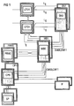
- FIG. 1 shows the typical system architecture of a communication system with unduplicated peripheral devices LTG1 ... LTGn. On the output side, they are connected to participants or other communication systems; the information originating from the last two are received by the peripheral devices LTG1 ... LTGn and fed to the redundant switching network SN0, SN1 via connections Lij. Furthermore, the peripheral devices LTG1 ... LTGn are connected via further connections Iij to the redundant message distribution units MB0, MB1, which in turn are connected via further connections Iij to the redundantly designed devices for handling central protocol completion tasks PRH (e.g. central drawing channel for No.
- PRH central protocol completion tasks
- the switching network SN0, SN1 and with the also redundant central control device CP0, CP1 are connected.
- the latter is connected to a double mass storage device SP.
- interface units IF are provided on the central control device CP0, CP1 for connecting operating elements or for alarming.
- the switching network SN0, SN1, the message distribution units MB0, MB1, the devices for handling central protocol completion tasks PRH0, PRH1, the central control device CP0, CP1 as well as the mass storage devices SP and the interface units IF are thus provided in duplicate in the communication system.
- the peripheral devices LTG1 ... LTGn are unduplicated in the present exemplary embodiment.
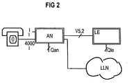
- the Access Network AN has a concentration function; with a subscriber concentration of 8: 1, for example, up to 4000 subscribers can be connected to a V5.2 interface of an Access Network AN with 16 PCM30 systems.
- the access network AN can have access to a leased line network LLN and can be connected via one or more V5.2 interfaces to communication systems with a local exchange function LE (Local Exchange).
- the communication system LE has an interface Qle and the access network AN has an interface Qan.
- the administration of the V5.2 interface and the associated participants is carried out functionally separately via the interfaces Qan, Qle via the Access Network AN and the communication system LE; administration is not (logically) via the V5.2 interface itself.
- Each V5.2 interface provides access to the LE communication system via 1 to 16 PCM30 connections.
- a maximum of three physical communication channels CC can be set up for each PCM30 connection in time slot 15, 16, 31.
- a time slot not used as a communication channel CC is available as a bearer channel, this applies in particular to time slot 16.
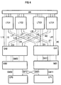
- FIG. 4 shows the relationships of the configuration according to FIG. 3 as the initial state before a software change.
- the Access Network AN is introduced to the peripheral devices LTG1 ... LTG4 via a V5.2 interface.
- peripheral connection device LTG1 ... LTG4 four PCM30 systems (see also Fig. 3) are used to connect a V5.2 Interface with a total of 16 PCM30 lines used.
- a switching network SN0, SN1, message distribution units MB0, MB1 and a central control device CP0, CP1 are shown as the central device of the communication system, all the latter devices being duplicated for security reasons.
- the peripheral device LTG3 terminates the PCM30 system (primary link) leading the active BCC / CTR C-channel of the V5.2 interface, which is why the function of the V5.2 master is assigned to it via the database. This means that it maintains all current states of the V5.2 interface.
- the assignments of the voice channels are stored here.
- the assignment of the Access Network participants to the voice channels is also carried out here.
- the peripheral device LTG2 terminates the PCM30 system (secondary link), which brings the standby BCC / CTR C-channel of the V5.2 interface, which is why all data of the master function are kept in sufficient redundancy for reasons of failure.
- the subscriber's signaling information is transmitted in a dedicated communication channel CC to one of the peripheral devices LTG1 ... LTG4. This can be the peripheral device LTG1, for example. It is then - due to the connection of this subscriber - responsible for signaling the subscriber.
- the peripheral device with master function LTG3 now uses a connection to assign the peripheral device LTG1 responsible for signaling to a peripheral device entrusted with carrying out switching tasks.
- This can be, for example, the LTG4 peripheral device. It is then responsible for the one-off connection or disconnection of this connection.
- the signaling information of the abovementioned subscriber brought in via the V5.2 communication channel are fed to the protocol termination capacity of the peripheral device LTG1 and subjected to an evaluation there.
- a transformation of the signaling information into a system-internal message is carried out here, which is then fed to the peripheral device LTG4 in the following, for example, via the message distribution unit MB0.
- the control of the peripheral device LTG is integrated in the signaling path.
- the peripheral device LTG1 is connected to the switching network half SN0 via connections L10 and to the redundant switching network half SN1 via connection L11. There are also connections I10 between the peripheral device LTG1 and the message distribution unit MB0 and connections I11 to the message distribution unit MB1.
- the other peripheral devices are connected to the central devices of the communication system in the same way:
- the peripheral device LTG2 is connected to the switching network half SN0 via connections L20 and to the switching network half SN1 via connections L21, while connections I20 to the message distribution unit MB0 and connections I21 to the message distribution unit MB1 also exist.
- the switching network SN0, the message distribution unit MB0, the central protocol termination device PRH0 and the central control device CP0 define the system half 0 below, which, as just shown - for the purpose of changing the software, the peripheral devices LTG1, LTG2 are assigned.
- the peripheral devices LTG3, LTG4 are connected to the central devices.
- the former is connected to the switching network half SN0 or the redundant switching network half SN1 via connecting lines L30, L31.
- Connections I30, I31 also exist to the message distribution unit MB0 or to the message distribution unit MB1, which is designed redundantly for this purpose.
- the peripheral device LTG4 is connected via connections L40, L41 to the switching matrix half SN0 or the redundantly designed switching matrix half SN1 and via connections I40, I41 to the message distribution unit MB0 or the redundant message distribution unit MB1.
- the switching network half SN1, the message distribution unit MB1, the central protocol termination device PRH1 and the central control device CP1 define the system half 1 below, which - as also shown - the peripheral devices LTG3, LTG4 are assigned for the purpose of changing the software. Furthermore, the switching network half SN0 is connected to the message distribution unit MB0 via connections SM00 in the same way as the switching network half SN1 is connected to the message distribution unit MB1 via connections SM11.
- the message distribution units MB0, MB1 are in turn connected to the central control device CP0, CP1 via connections CM00 and CM11, as shown in FIG. At the same time, there is a crossover between the message distribution units MB0, MB1 and the central control device CP0, CP1 via connections CM10, CM01.
- Fig. 4 shows a configuration as it appears immediately before the software change.
- approximately 50% of the traffic and, if the signaling is distributed uniformly over the peripheral devices LTG approximately 50% of the signaling is handled via the peripheral half 0.
- about 50% of the traffic and 50% of the signaling are handled via the peripheral half 1.
- the redundant normal operating mode of the communication system prevails, which means that both are generally Switching network halves SN0, SN1 must be switched through for each connection, the devices MB0, MB1, PRH0, PRH1 as well as CP0 and CP1 operate in their redundant mode, for example active / stand by or load sharing.
- the peripheral devices belonging to the system half that is to say the peripheral devices LTG1, LTG2, should first be loaded with new software.
- the traffic conducted via the peripheral devices LTG1, LTG2 is first thinned out in the redundant normal operating mode. This means that although existing connections are still permitted and processed, new connections are no longer permitted via this peripheral half. After a certain time, only a small part of the total traffic is then processed via the peripheral half 0, for example 3% of the traffic.
- the peripheral half 1 continues to provide approximately 50% of the traffic capacity of the normal operating state. The waiting time for traffic thinning can be set in advance if necessary.
- a further embodiment of the invention consists in allowing a threshold value, which is also defined in advance. Once this has been reached, the 'thinning out process' is also considered to be complete, which then creates a defined initial state in both cases. In a further embodiment of the invention, the thinning process to accelerate the method for changing the software can be omitted.
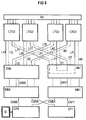
- the communication channels CC of peripheral half 0 are switched to peripheral half 1.
- Fig. 5 shows the relevant conditions.
- the communication channels CC arriving via the interface V5.2 are inserted in the peripheral devices LTG1, LTG2 in voice channels and then to the switching network half SN1 via the Transfer connections L11, L21.
- the relevant communication channels CC are switched to the peripheral devices LTG3, LTG4 via connections L41, L31.
- the communication channels are treated as if they were supplied via the connected V5.2 interface. If the voice channels on the connecting lines L11, L21, L31, L41 required for the through-connection are still used in terms of switching technology, the relevant connections are triggered before the communication channels CC are switched over.
- the switching-related residual traffic still handled by the peripheral half 0 is now triggered, the peripheral devices on the system side 0 are then switched off, and consequently no switching-related traffic is processed via this.
- the thinning out of the traffic in order to accelerate the method for changing the software can be omitted and the triggering can take place immediately.
- the traffic conducted via the peripheral devices on the system side 0 can also be triggered before the communication channels CC of the peripheral half 0 are switched to the peripheral half 1.
- the peripheral devices LTG1, LTG2 now have the inactive state, but the connection of the communication channels CC to the remaining system side 1 is retained. Furthermore, the old software is still loaded in the memories of the peripheral device LTG1, LTG2.
- the switching matrix half SN0, the message distribution unit MB0, the protocol termination unit PRH0 and the central control device CP0 are switched off.
- the crossover connections CM10, CM01 and the connections I11, I21 are thus activated.
- the associated protocol termination capacities are also inactive with the peripheral devices LTG1, LTG2. Therefore, the signaling information transmitted in the communication channels PC is not processed but only passed transparently to the switching network SN1.
- the central control device CP0 of the system half 0 is connected to an external storage medium SP, which can be configured as a floppy disk drive. Other storage media can optionally be used.
- the software to be loaded is removed from the floppy disk drive D and fed to the central control device CP0. From there, the transmission takes place via the connections CM00, SM00 and I10 or I20 into the memories of the peripheral devices LTG1, LTG2.
- the switching traffic is maintained with approx. 50% of the traffic capacity of the normal operating state.
- the loadable software parts of the devices PRH0, SN0, MB0 and in particular CP0 can advantageously also be loaded with a new associated software version.
- the redirection of the communication channels CC of system half 0 redirected via system half 1 is switched back again.
- system half 0 is again fully available for switching traffic, which means that an intermediate state is reached, which in principle corresponds to the defined initial state shown in FIG. 4, in that traffic can be handled 50% over both peripheral halves.
- system side 0 can only be active in terms of switching technology if there is a possibility of cross-communication between the system halves, which would give system half 0 access to the V5.2 interface controller, for example to assign voice channels to the V5.2 interface.
- the parallel operation of system half 0 with the new software version and system half 1 with the old software version is only possible if this cross communication option is available, which can be used advantageously for thinning out traffic via system half 1.
- System half 1 is then loaded with the new software.
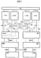
- the communication channels CC of system half 1 are switched to system half 0 - as shown in FIG. 7.
- the communication channels CC arriving via the interface V5.2 are inserted in the peripheral devices LTG3, LTG4 in voice channels and then transmitted to the switching network half SN0 via the connections L30, L40.
- the relevant communication channels CC are switched to the peripheral devices LTG1, LTG2 via connections L10, L20.
- the communication channels CC are treated as if they were supplied via the connected V5.2 interface.
- the central control device CP1 of the system half 1 is connected to an external storage medium SP, which can also be configured as a floppy disk drive D. Alternatively, other storage media can also be used here.
- the software to be loaded is removed from the floppy disk drive D and fed to the central control device CP1. From there, the software is transferred via the connections CM11, SM11 and I31 or I41 to the memories of the peripheral devices LTG3, LTG4.
- the switching traffic is maintained with approximately 50% of the traffic capacity of the normal operating state via system half 0.
- the loadable software parts of the devices PRH1, SN1, MB1 and in particular CP1 can advantageously also be loaded with a new software version.
- the central devices SN1, MB1, PRH1, CP1 which may also be supplied with new software, are switched off and the peripheral devices LTG3, LTG4 of system side 0 are switched on.
- System page 0 with the full periphery population LTG1 ... LTG4 hereby offers switching traffic via all V5.2 interfaces.
- the redirection of the communication channels CC of the peripheral half 1 redirected via the system half 0 is canceled again. This means that the entire system periphery is again fully available to switching traffic without switching the communication channels.
- redundant operation is restored by connecting the central components SN1, MB1, PRH1 and CP1.
- the software change has ended and the normal operating situation has been restored.
- connections can additionally be made between two, one system half each associated peripheral devices are provided. These can be connections between the peripheral devices LTG1, LTG4, for example.
- the communication channels CC can then be fed directly above it from, for example, the peripheral device LTG2 to the peripheral device LTG4.
- the communication channels CC can be redirected to an upstream cross-connect system based on 64 kbit / s channels.
- the protocol termination capacities are maintained in the active state.
- the information can then be transferred to other peripheral devices via other outputs.
- the V5.2-specific protocols can then be completed in the peripheral devices terminating the associated PCM30 routes, as a result of which the signaling and ISDN D-channel packet data introduced in the communication channels CC can be forwarded as system-internal messages to the half of the system that is still in operation.
- the message distribution unit that is still in operation or additional physical connections inserted between two peripheral devices of both peripheral halves can be used as the basis for the cross communication between the system halves instead of the central cross connection CM10, CM01.
- the time position or channel number which is used for switching through the communication channels CC, can be clearly known from the connection position and time slot number of the communication channels, so that cross-communication for transferring the time position or channel number between the system halves is omitted.
- the communication channels CC can also be routed to central protocol termination capacities, as can occur with greater flexibility in system architectures.
- the relationship of all ISDN packet subscribers to all packet networks accessible to them in normal operation can be maintained for the full duration of the software change, in particular for the duration of the non-redundant operation.
Landscapes
- Engineering & Computer Science (AREA)
- Computer Networks & Wireless Communication (AREA)
- Data Exchanges In Wide-Area Networks (AREA)
- Stored Programmes (AREA)
- Computer And Data Communications (AREA)
- Information Transfer Between Computers (AREA)
- Two-Way Televisions, Distribution Of Moving Picture Or The Like (AREA)
Applications Claiming Priority (2)
| Application Number | Priority Date | Filing Date | Title |
|---|---|---|---|
| DE4422805A DE4422805C1 (de) | 1994-06-29 | 1994-06-29 | Verfahren zum Laden von Software in Kommunikationssystemen mit nichtredundaten, dezentralen Einrichtungen |
| DE4422805 | 1994-06-29 |
Publications (3)
| Publication Number | Publication Date |
|---|---|
| EP0690635A2 true EP0690635A2 (fr) | 1996-01-03 |
| EP0690635A3 EP0690635A3 (fr) | 1999-10-13 |
| EP0690635B1 EP0690635B1 (fr) | 2003-10-22 |
Family
ID=6521841
Family Applications (1)
| Application Number | Title | Priority Date | Filing Date |
|---|---|---|---|
| EP95109561A Expired - Lifetime EP0690635B1 (fr) | 1994-06-29 | 1995-06-20 | Procédé de chargement de programmes dans des systèmes de communication avec des équipements décentralisés et non-redundants |
Country Status (5)
| Country | Link |
|---|---|
| EP (1) | EP0690635B1 (fr) |
| AT (1) | ATE252808T1 (fr) |
| DE (2) | DE4422805C1 (fr) |
| DK (1) | DK0690635T3 (fr) |
| FI (1) | FI953220A7 (fr) |
Cited By (3)
| Publication number | Priority date | Publication date | Assignee | Title |
|---|---|---|---|---|
| WO1999001978A3 (fr) * | 1997-07-03 | 1999-03-25 | Nokia Telecommunications Oy | Procede de transmission de trafic de donnees dans un systeme de telecommunication |
| WO2001084792A1 (fr) * | 2000-05-04 | 2001-11-08 | Marconi Communications Limited | Procede et passerelle permettant d'effectuer une commutation en ligne d'un logiciel dans un systeme de communication |
| EP1107511A3 (fr) * | 1999-12-08 | 2004-01-07 | Nortel Networks Limited | Système, dispositif, et méthode pour l'arrêt non-disruptif dans un réseau de transmission |
Families Citing this family (7)
| Publication number | Priority date | Publication date | Assignee | Title |
|---|---|---|---|---|
| DE19506961C1 (de) * | 1995-02-28 | 1996-10-17 | Siemens Ag | Verfahren zum Anschluß von Access-Networks mit V5.2-Schnittstellen an Kommunikationssysteme mit nichtredundanten peripheren Einrichtungen |
| DE19524029C1 (de) * | 1995-06-30 | 1996-11-07 | Siemens Ag | Verfahren zum Anschluß von Access-Networks mit V5.2-Schnittstellen an Kommunikationssysteme mit nichtredundanten peripheren Einrichtungen |
| DE19533961A1 (de) * | 1995-09-13 | 1997-03-20 | Siemens Ag | Verfahren zum Laden von Software in Kommunikationssystemen mit nichtredundanten, dezentralen Einrichtungen |
| DE19611426A1 (de) * | 1996-03-22 | 1997-09-25 | Siemens Ag | Optisches Sternnetz |
| FI103371B1 (fi) * | 1996-06-13 | 1999-06-15 | Nokia Telecommunications Oy | Menetelmä ja järjestelmä hätäliikenteen varmistamiseksi |
| DE19843048C2 (de) * | 1998-09-19 | 2000-08-17 | Nokia Networks Oy | Verfahren für einen Softwarezugriffswechsel in einem Netzwerkknoten eines Telekommunikationsnetzwerkes sowie ein zum Durchführen eines solchen Verfahrens geeigneter Netzwerkknoten |
| DE19946968A1 (de) * | 1999-09-30 | 2001-04-12 | Siemens Ag | Verfahren zum Anschluß von Teilnehmer-Anschlußkonzentratoren |
Citations (1)
| Publication number | Priority date | Publication date | Assignee | Title |
|---|---|---|---|---|
| DE4319877C1 (de) | 1993-06-16 | 1994-06-16 | Siemens Ag | Verfahren zur Inbetriebnahme von dezentralen, redundanten Einrichtungen in Kommunikationssystemen |
Family Cites Families (2)
| Publication number | Priority date | Publication date | Assignee | Title |
|---|---|---|---|---|
| CA2107755C (fr) * | 1992-11-16 | 1998-07-07 | Paul Elliott Janssen | Systeme de telecommunication a facilite de reconfiguration accrue |
| DK0607493T3 (da) * | 1993-01-18 | 1999-08-30 | Siemens Ag | Realtidsstyresystem |
-
1994
- 1994-06-29 DE DE4422805A patent/DE4422805C1/de not_active Expired - Fee Related
-
1995
- 1995-06-20 EP EP95109561A patent/EP0690635B1/fr not_active Expired - Lifetime
- 1995-06-20 AT AT95109561T patent/ATE252808T1/de not_active IP Right Cessation
- 1995-06-20 DE DE59510810T patent/DE59510810D1/de not_active Expired - Fee Related
- 1995-06-20 DK DK95109561T patent/DK0690635T3/da active
- 1995-06-29 FI FI953220A patent/FI953220A7/fi unknown
Patent Citations (1)
| Publication number | Priority date | Publication date | Assignee | Title |
|---|---|---|---|---|
| DE4319877C1 (de) | 1993-06-16 | 1994-06-16 | Siemens Ag | Verfahren zur Inbetriebnahme von dezentralen, redundanten Einrichtungen in Kommunikationssystemen |
Cited By (5)
| Publication number | Priority date | Publication date | Assignee | Title |
|---|---|---|---|---|
| WO1999001978A3 (fr) * | 1997-07-03 | 1999-03-25 | Nokia Telecommunications Oy | Procede de transmission de trafic de donnees dans un systeme de telecommunication |
| US6370243B2 (en) | 1997-07-03 | 2002-04-09 | Nokia Networks Oy | Method for transmitting data traffic in a telecommunications system |
| EP1107511A3 (fr) * | 1999-12-08 | 2004-01-07 | Nortel Networks Limited | Système, dispositif, et méthode pour l'arrêt non-disruptif dans un réseau de transmission |
| WO2001084792A1 (fr) * | 2000-05-04 | 2001-11-08 | Marconi Communications Limited | Procede et passerelle permettant d'effectuer une commutation en ligne d'un logiciel dans un systeme de communication |
| CN100459599C (zh) * | 2000-05-04 | 2009-02-04 | 爱立信股份有限公司 | 在通信系统中实现在线式软件切换的方法和网关 |
Also Published As
| Publication number | Publication date |
|---|---|
| DE59510810D1 (de) | 2003-11-27 |
| EP0690635B1 (fr) | 2003-10-22 |
| EP0690635A3 (fr) | 1999-10-13 |
| FI953220A0 (fi) | 1995-06-29 |
| FI953220A7 (fi) | 1995-12-30 |
| DK0690635T3 (da) | 2003-11-24 |
| ATE252808T1 (de) | 2003-11-15 |
| DE4422805C1 (de) | 1995-11-30 |
Similar Documents
| Publication | Publication Date | Title |
|---|---|---|
| EP0763953B1 (fr) | Procédé pour le chargement de software dans des systèmes de communication équipés de dispositif décentralisés et non-redondants | |
| EP0690635B1 (fr) | Procédé de chargement de programmes dans des systèmes de communication avec des équipements décentralisés et non-redundants | |
| EP0291789B1 (fr) | Montage de circuit pour centraux de télécommunication multiplex à division dans le temps, en particulier des centraux téléphoniques MIC avec des groupes de connexion connectés à un réseau de commutation | |
| EP0448734A1 (fr) | Disposition de circuit pour tester par routine l'interface entre les groupes de transmission et le réseau de commutation d'un central de télécommunication à MIC | |
| EP0291790B1 (fr) | Circuits pour centraux de télécommunication, en particulier centraux téléphoniques MIC à multiplexage temporel, avec des étages de commutation décentralisés connectés à un réseau de commutation central | |
| EP0141246B1 (fr) | Méthode pour l'exploitation d'un multiprocesseur de commande, en particulier pour l'unité de commande centrale d'un système de commutation téléphonique | |
| DE69836083T2 (de) | Verfahren zur kaskadierung von v5 schnittstellen | |
| EP0294644B1 (fr) | Procédé pour le fonctionnement d'un montage pour un central de télécommunication, à commande centralisée, en particulier un central téléphonique MIC avec une partie centrale et avec des groupes de connexion connectés à cette partie centrale | |
| EP0419920B1 (fr) | Circuit pour un central de télécommunication à commande centrale, en particulier un central téléphonique MIC avec un processeur central de coordination et des groupes de terminaux décentralisés avec des processeurs de groupe | |
| EP0751692B1 (fr) | Procédé pour la connexion de réseaux d'accès avec interfaces V5.2 à des systèmes de communication pourvus de dispositifs périphériques non-redondants | |
| EP0763952B1 (fr) | Procédé pour le stockage de données relatives aux abonnés dans des systèmes de communication | |
| EP0365905B1 (fr) | Procédé pour contrôler centralement des centraux de télécommunication | |
| EP0360065B1 (fr) | Procédé de contrôle de centraux de télécommunication, en particulier centraux téléphoniques MIC à division dans le temps avec plusieurs réseaux de commutation distribués connectés à un réseau de commutation central | |
| EP1285543B1 (fr) | Dispositif pour optimiser des unites peripheriques d'un systeme de communication | |
| WO2002051195A1 (fr) | Dispositif et procede permettant de connecter en mode paquets des abonnes a des reseaux isdn/pstn classiques a un systeme de commutation | |
| EP1104205A1 (fr) | Procédé pour optimiser le traitement de connexions à l'extérieur d'un central de commutation | |
| EP0337163B1 (fr) | Circuit pour commuter d'une opération normale à une opération de secours et inversement dans une installation de commutation téléphonique | |
| DE3634863C2 (de) | Schaltungsanordnung für eine zentralgesteuerte Fernmeldevermittlungsanlage, insbesondere PCM-Fernsprechvermittlungsanlage, mit einem Zentralteil und mit diesem verbundenen Anschlußgruppen | |
| DE3606846C2 (fr) | ||
| DE69226221T2 (de) | Redundanz-Verfahren für ein Vermittlungssystem, insbesondere eine Fernsprechvermittlungsanlage | |
| DE19528067C1 (de) | Verfahren zum Verarbeiten von Fehlermeldungen von systemexternen Einrichtungen in Kommunikationssystemen | |
| EP0888696B1 (fr) | Procede pour la transmission d'informations entre une source d'informations et des recepteurs d'informations | |
| EP0876068B1 (fr) | Concentrateur pour la connection des abonnés | |
| DE3030966C2 (de) | Steuereinrichtung für Fernmelde-, insbesondere Fernsprechvermittlungsanlagen | |
| EP1103159B1 (fr) | Procede pour faire fonctionner une unite terminale dans un central telephonique |
Legal Events
| Date | Code | Title | Description |
|---|---|---|---|
| PUAI | Public reference made under article 153(3) epc to a published international application that has entered the european phase |
Free format text: ORIGINAL CODE: 0009012 |
|
| AK | Designated contracting states |
Kind code of ref document: A2 Designated state(s): AT BE DE DK FR GB IT |
|
| PUAL | Search report despatched |
Free format text: ORIGINAL CODE: 0009013 |
|
| AK | Designated contracting states |
Kind code of ref document: A3 Designated state(s): AT BE DE DK FR GB IT |
|
| 17P | Request for examination filed |
Effective date: 19991206 |
|
| GRAH | Despatch of communication of intention to grant a patent |
Free format text: ORIGINAL CODE: EPIDOS IGRA |
|
| GRAS | Grant fee paid |
Free format text: ORIGINAL CODE: EPIDOSNIGR3 |
|
| GRAA | (expected) grant |
Free format text: ORIGINAL CODE: 0009210 |
|
| AK | Designated contracting states |
Kind code of ref document: B1 Designated state(s): AT BE DE DK FR GB IT |
|
| REG | Reference to a national code |
Ref country code: GB Ref legal event code: FG4D Free format text: NOT ENGLISH |
|
| REG | Reference to a national code |
Ref country code: DK Ref legal event code: T3 |
|
| REF | Corresponds to: |
Ref document number: 59510810 Country of ref document: DE Date of ref document: 20031127 Kind code of ref document: P |
|
| GBT | Gb: translation of ep patent filed (gb section 77(6)(a)/1977) |
Effective date: 20040106 |
|
| PGFP | Annual fee paid to national office [announced via postgrant information from national office to epo] |
Ref country code: AT Payment date: 20040519 Year of fee payment: 10 |
|
| PGFP | Annual fee paid to national office [announced via postgrant information from national office to epo] |
Ref country code: DK Payment date: 20040604 Year of fee payment: 10 |
|
| PGFP | Annual fee paid to national office [announced via postgrant information from national office to epo] |
Ref country code: BE Payment date: 20040624 Year of fee payment: 10 |
|
| ET | Fr: translation filed | ||
| PLBE | No opposition filed within time limit |
Free format text: ORIGINAL CODE: 0009261 |
|
| STAA | Information on the status of an ep patent application or granted ep patent |
Free format text: STATUS: NO OPPOSITION FILED WITHIN TIME LIMIT |
|
| 26N | No opposition filed |
Effective date: 20040723 |
|
| PG25 | Lapsed in a contracting state [announced via postgrant information from national office to epo] |
Ref country code: IT Free format text: LAPSE BECAUSE OF NON-PAYMENT OF DUE FEES;WARNING: LAPSES OF ITALIAN PATENTS WITH EFFECTIVE DATE BEFORE 2007 MAY HAVE OCCURRED AT ANY TIME BEFORE 2007. THE CORRECT EFFECTIVE DATE MAY BE DIFFERENT FROM THE ONE RECORDED. Effective date: 20050620 Ref country code: AT Free format text: LAPSE BECAUSE OF NON-PAYMENT OF DUE FEES Effective date: 20050620 |
|
| PG25 | Lapsed in a contracting state [announced via postgrant information from national office to epo] |
Ref country code: DK Free format text: LAPSE BECAUSE OF NON-PAYMENT OF DUE FEES Effective date: 20050630 Ref country code: BE Free format text: LAPSE BECAUSE OF NON-PAYMENT OF DUE FEES Effective date: 20050630 |
|
| REG | Reference to a national code |
Ref country code: DK Ref legal event code: EBP |
|
| PGFP | Annual fee paid to national office [announced via postgrant information from national office to epo] |
Ref country code: DE Payment date: 20070630 Year of fee payment: 13 |
|
| PGFP | Annual fee paid to national office [announced via postgrant information from national office to epo] |
Ref country code: GB Payment date: 20070621 Year of fee payment: 13 |
|
| BERE | Be: lapsed |
Owner name: *SIEMENS A.G. Effective date: 20050630 |
|
| PGFP | Annual fee paid to national office [announced via postgrant information from national office to epo] |
Ref country code: FR Payment date: 20070615 Year of fee payment: 13 |
|
| REG | Reference to a national code |
Ref country code: FR Ref legal event code: TP |
|
| GBPC | Gb: european patent ceased through non-payment of renewal fee |
Effective date: 20080620 |
|
| REG | Reference to a national code |
Ref country code: GB Ref legal event code: 732E Free format text: REGISTERED BETWEEN 20090129 AND 20090204 |
|
| REG | Reference to a national code |
Ref country code: FR Ref legal event code: ST Effective date: 20090228 |
|
| PG25 | Lapsed in a contracting state [announced via postgrant information from national office to epo] |
Ref country code: DE Free format text: LAPSE BECAUSE OF NON-PAYMENT OF DUE FEES Effective date: 20090101 |
|
| PG25 | Lapsed in a contracting state [announced via postgrant information from national office to epo] |
Ref country code: GB Free format text: LAPSE BECAUSE OF NON-PAYMENT OF DUE FEES Effective date: 20080620 |
|
| PG25 | Lapsed in a contracting state [announced via postgrant information from national office to epo] |
Ref country code: FR Free format text: LAPSE BECAUSE OF NON-PAYMENT OF DUE FEES Effective date: 20080630 |