EP0690660B1 - Dispositif et procédé de chauffage d'un liquide ionique en écoulement - Google Patents
Dispositif et procédé de chauffage d'un liquide ionique en écoulement Download PDFInfo
- Publication number
- EP0690660B1 EP0690660B1 EP95401569A EP95401569A EP0690660B1 EP 0690660 B1 EP0690660 B1 EP 0690660B1 EP 95401569 A EP95401569 A EP 95401569A EP 95401569 A EP95401569 A EP 95401569A EP 0690660 B1 EP0690660 B1 EP 0690660B1
- Authority
- EP
- European Patent Office
- Prior art keywords
- liquid
- electrodes
- enclosure
- section
- electrode
- Prior art date
- Legal status (The legal status is an assumption and is not a legal conclusion. Google has not performed a legal analysis and makes no representation as to the accuracy of the status listed.)
- Expired - Lifetime
Links
- 238000010438 heat treatment Methods 0.000 title claims description 17
- 238000000034 method Methods 0.000 title claims description 9
- 239000012530 fluid Substances 0.000 title description 12
- 239000007788 liquid Substances 0.000 claims description 30
- 239000002608 ionic liquid Substances 0.000 claims description 7
- 238000001816 cooling Methods 0.000 claims description 4
- 229910052751 metal Inorganic materials 0.000 claims description 4
- 239000002184 metal Substances 0.000 claims description 4
- 239000011810 insulating material Substances 0.000 claims description 3
- 230000005684 electric field Effects 0.000 claims description 2
- 235000013305 food Nutrition 0.000 description 5
- 230000001954 sterilising effect Effects 0.000 description 3
- 238000004659 sterilization and disinfection Methods 0.000 description 3
- 238000007789 sealing Methods 0.000 description 2
- OKTJSMMVPCPJKN-UHFFFAOYSA-N Carbon Chemical compound [C] OKTJSMMVPCPJKN-UHFFFAOYSA-N 0.000 description 1
- 229910001260 Pt alloy Inorganic materials 0.000 description 1
- 238000010793 Steam injection (oil industry) Methods 0.000 description 1
- 229910001069 Ti alloy Inorganic materials 0.000 description 1
- RTAQQCXQSZGOHL-UHFFFAOYSA-N Titanium Chemical compound [Ti] RTAQQCXQSZGOHL-UHFFFAOYSA-N 0.000 description 1
- 238000012550 audit Methods 0.000 description 1
- 230000000295 complement effect Effects 0.000 description 1
- 235000013365 dairy product Nutrition 0.000 description 1
- 238000010790 dilution Methods 0.000 description 1
- 239000012895 dilution Substances 0.000 description 1
- 235000021183 entrée Nutrition 0.000 description 1
- 210000004907 gland Anatomy 0.000 description 1
- 229910002804 graphite Inorganic materials 0.000 description 1
- 239000010439 graphite Substances 0.000 description 1
- 239000007943 implant Substances 0.000 description 1
- 239000000463 material Substances 0.000 description 1
- 239000013528 metallic particle Substances 0.000 description 1
- 230000007935 neutral effect Effects 0.000 description 1
- 235000011837 pasties Nutrition 0.000 description 1
- 239000004810 polytetrafluoroethylene Substances 0.000 description 1
- 229920001343 polytetrafluoroethylene Polymers 0.000 description 1
- 238000004513 sizing Methods 0.000 description 1
- 239000010935 stainless steel Substances 0.000 description 1
- 229910001220 stainless steel Inorganic materials 0.000 description 1
- 239000010936 titanium Substances 0.000 description 1
- 229940088594 vitamin Drugs 0.000 description 1
- 229930003231 vitamin Natural products 0.000 description 1
- 235000013343 vitamin Nutrition 0.000 description 1
- 239000011782 vitamin Substances 0.000 description 1
- 150000003722 vitamin derivatives Chemical class 0.000 description 1
Images
Classifications
-
- H—ELECTRICITY
- H05—ELECTRIC TECHNIQUES NOT OTHERWISE PROVIDED FOR
- H05B—ELECTRIC HEATING; ELECTRIC LIGHT SOURCES NOT OTHERWISE PROVIDED FOR; CIRCUIT ARRANGEMENTS FOR ELECTRIC LIGHT SOURCES, IN GENERAL
- H05B3/00—Ohmic-resistance heating
- H05B3/60—Heating arrangements wherein the heating current flows through granular powdered or fluid material, e.g. for salt-bath furnace, electrolytic heating
Definitions
- the present invention relates to a device for heating of a flowing ionic liquid comprising at least one elongated enclosure of liquid circulation, two identical electrodes arranged respectively at the entrance and at the exit of the enclosure and the means of generating a field electric between said electrodes arranged for heat the liquid by electrical conduction direct within said liquid.
- Such electric conduction heating direct is also known as “ohmic” heating.
- the invention also relates to a method of ohmic heating and / or sterilization of a flowing ionic liquid.
- Food products are particularly heat-sensitive and their vitamin, taste and are directly affected by the duration of treatment.
- the scrapers with a scraped surface better suited liquids with high viscosity require a long processing time.
- the present invention aims to provide a responsive heating device and method better than previously known requirements of practice, especially in that it allows obtain very short heating times, the order of the second, in a simple and easy to implement.
- the invention provides a device for heating a flowing ionic liquid comprising at least one enclosure made of elongated insulating material for circulation of the liquid, two identical electrodes disposed respectively at the inlet and at the outlet of the enclosure and means for generating an electric field between said electrodes arranged to heat the liquid by direct electrical conduction within said liquid, characterized in that the enclosure comprises a tubular central zone connected to an inlet convergent and to an outlet diverging, and in that the electrodes are openwork surface elements suitable for being traversed by the liquid and respectively fixed to said inlet converger and to said audit diverging outlet, perpendicular to the direction of flow.
- the invention also provides a method of heating of an ionic liquid flowing in an enclosure between two electrodes whereby the liquid is passed through a converging box through a first electrode, then in a tubular part, then in a divergent box through a second electrode, the alternating voltage applied between the electrodes being between of the order of a few hundred volts, per example 400 Volts, and of the order of 5000 Volts.
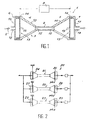
- Figure 1 shows a heater 1 of an ionic liquid 2 in flow.
- the device comprises an enclosure 3 in insulating material, for example PTFE, circulation of the liquid and two electrodes 4 and 5 identical, in the form of a surface element, arranged respectively at entrance 6 and at exit 7 of the enclosure.
- Means 8 for generating a voltage alternative between electrodes 4 and 5 included between a few hundred volts, for example 400 Volts, and 10,000 Volts, for example 5,000 Volts, are also planned.
- Enclosure 3 has a central area tubular 9 whose cross-section is calculated as a function the flow rate of the liquid and the desired residence time, a converging cone 10 for entering the liquid and a divergent cone 11 for liquid outlet, symmetrical of the cone 10.
- the internal diameter of the small base 12 of cones is equal to the internal diameter of the tube 9, the internal diameter of large bases 13 of cones being chosen according to the electrodes.
- the cones 10 and 11 are identical, but their sizing can also be different to take into account in particular the conductivity electrical fluids which varies depending on the temperature.
- Each cone has on the side of its large base an internal shoulder 14, on which are plated electrodes 4 and 5 respectively.
- Each electrode is for example constituted by a metal disc with a diameter equal to that of the large base increased on both sides of a thickness corresponding to, or slightly less than, the width of the shoulder.
- the disc consists of a material which depends on the product to be treated. It can be stainless steel, graphite, titanium or platinum alloy, etc.
- the discs are drilled with holes 15, the number, diameter and distribution are function the flow rate and viscosity of the liquid to be heated.
- the invention is not limited to electrodes formed by perforated plates, but concerns also other embodiments of elements openwork surfaces such as shaped electrodes of grid or constituted by case containing metallic particles.
- the electrodes are connected to circuit 8 voltage generator, for example via a nut welded at their periphery, said nut receiving a threaded rod fitted with a sealing cable gland (not shown).
- the device 1 also includes housings or cylindrical flanges 16 and 17, for connection with the fluid supply and discharge circuit (not shown). These housings serve as covers sealing at each end and allow the holding the electrodes in place by compressing them on the shoulders. Each case has a central connection port 18 inlet or fluid outlet 19.
- Such a device makes it possible to obtain a time of very short heating thanks to its geometry. Indeed, the electrical resistance represented by the fluid contained in a 10 or 11 cone is much more weak than that of the fluid contained in the tube central 9.
- the electrical power dissipated, and therefore the heating of the fluid therefore takes place almost all in the central tube, or in less than one second depending on the diameter chosen.
- the inlet cone 10 can also serve as product preheating zone, while the cone output can be combined with a rapid cooling (not shown).
- the end cones also allow to implant large diameter electrodes and therefore to decrease the current density on these, this which limits the electrochemical phenomena which have takes place at the metal product interface.
- the table below gives the characteristic parameters of an apparatus of the type described with reference to FIG. 1 for a fluid whose characteristics correspond to table No. 2, the electrical operating parameters being given in table 3.
- FIG. 2 shows a device 20 comprising three identical speakers 21, 22, 23, in parallel, hydraulic, for example of the type described above, whose electrodes are supplied with three-phase.
- the electrode 26 of the enclosure 21 is in phase (1) (ph 1 on the drawing).
- the electrode 28 of the enclosure 22 is in phase (2) (ph 2), the electrode 25 of enclosure 23 is in phase (3) (ph 3).
- the electrodes 24, 27 and 29 placed at the outlet of the enclosures 21, 22, 23 are connected to ground and system neutral.
- the viscous liquid to be sterilized at 160 ° C by example a dairy product, is supplied with pressure (for example under 4 bars) and introduced at 6 in the enclosure at a temperature of the order of 80 ° C., after preheating.
Landscapes
- Electrical Discharge Machining, Electrochemical Machining, And Combined Machining (AREA)
- Food Preservation Except Freezing, Refrigeration, And Drying (AREA)
- Physical Or Chemical Processes And Apparatus (AREA)
- Apparatus For Disinfection Or Sterilisation (AREA)
- Instantaneous Water Boilers, Portable Hot-Water Supply Apparatuses, And Control Of Portable Hot-Water Supply Apparatuses (AREA)
Description
caractérisé en ce que
l'enceinte comprend une zone centrale tubulaire raccordée à un convergeant d'entrée et à un divergeant de sortie, et en ce que les électrodes sont des éléments surfaciques ajourés propres à être traversés par le liquide et respectivement fixées audit convergeant d'entrée et audit divergeant de sortie, perpendiculairement au sens de l'écoulement.
- les dimensions des éléments surfaciques correspondent respectivement aux sections internes du divergeant et du convergeant à l'emplacement de leur fixation sur ces derniers ;
- les éléments surfaciques sont respectivement fixés aux extrémités externes par rapport à la zone centrale, du divergeant et du convergeant ;
- la zone centrale tubulaire est cylindrique, et le convergeant d'entrée et le divergeant de sortie sont des portions de cônes identiques dont la section intérieure de la petite base est égale à la section intérieure du tube, et dont la section intérieure de la grande base correspond à la surface active des électrodes ;
- les électrodes sont des plaques métalliques percées de trous de passage du liquide ;
- le divergeant de sortie peut être associé à un système de refroidissement ;
- le dispositif comporte deux boítiers de connexion avec le circuit d'alimentation et d'évacuation du liquide, respectivement disposés de part et d'autre de l'enceinte, à savoir un boítier d'alimentation du liquide de section correspondant à la plus grande section du convergeant auquel il est relié via la première électrode, et un boítier d'évacuation de section correspondant à la plus grande section du divergeant auquel ledit boítier d'évacuation est relié via la seconde électrode ;
- la section de la zone centrale tubulaire est inférieure ou égale à de l'ordre de cinq fois la surface d'une électrode, par exemple inférieure ou égale à dix fois cette dernière ;
- le dispositif peut comporter trois enceintes en parallèle, dont les électrodes sont couplées pour permettre une alimentation en triphasée.
- La figure 1 est une vue en coupe de l'enceinte du dispositif selon le mode de réalisation de l'invention plus particulièrement décrit ici.
- La figure 2 est une vue schématique d'un dispositif selon l'invention comportant trois enceintes du type de celle décrite en référence à la figure 1, alimentées en triphasée.
| CARACTERISTIQUES DE L'APPAREIL | |
| Ø du tube central | 0,010 m |
| L du tube | 0,100 m |
| volume tube | 0,008 l |
| débit du fluide | 0,100 m3/h |
| vitesse fluide tube central | 0,35 m/s |
| temps de séjour tube | 0,28 s |
| ⊘ électrodes | 0,100 m |
| distance électrode-tube | 0,080 m |
| volume d'une boíte (l) | 0,230 l |
| temps de séjour d'une boíte | 8,28 s |
| CARACTERISTIQUES DU FLUIDE | |
| masse volumique (kg/m3) | 1100 |
| chaleur massique (J/kg.K) | 4000 |
| température d'entrée (°C) | 80 |
| conductivité d'entrée (S/m) | 0,411 |
| température de sortie (°C) | 165 |
| conductivité de sortie (S/m) | 0,764 |
| PARAMETRES ELECTRIQUES | |
| puissance | 10,39 kw |
| tension | 5147 v |
| intensité | 2,02 A |
| densité de courant | 26 mA/cm2 |
| puissance boíte entrée | 9,73 % |
| conductivité de sortie (S/m) | 5,23 % |
Claims (10)
- Dispositif (1,20) de chauffage d'un liquide ionique (2) en écoulement comportant au moins une enceinte en matière isolante (3,21,22,23) allongée de circulation du liquide, deux électrodes (4,5 ; 26,24,28,27 ; 25,29) identiques, disposées respectivement à l'entrée (6) et à la sortie (7) de l'enceinte et des moyens (8) de génération d'un champ électrique entre lesdites électrodes agencé pour chauffer le liquide par conduction électrique directe au sein dudit liquide,
caractérisé en ce que
l'enceinte (3,21,22,23) comprend une zone centrale tubulaire (9) raccordée à un convergeant d'entrée (10) et à un divergeant de sortie (11), et en ce que les électrodes (4,5) sont des éléments surfaciques ajourés propres à être traversés par le liquide et respectivement fixées audit convergeant d'entrée et audit divergeant de sortie perpendiculairement au sens de l'écoulement. - Dispositif selon la revendication 1, caractérisé en ce que les dimensions des éléments surfaciques correspondent respectivement aux sections internes du divergeant et du convergeant à l'emplacement de leur fixation sur ces derniers.
- Dispositif selon la revendication 2, caractérisé en ce que la zone centrale tubulaire (9) est cylindrique, et en ce que le convergeant d'entrée (10) et le divergeant de sortie (11) sont des portions de cônes identiques dont la section intérieure de la petite base (12) est égale à la section intérieure du tube, et dont la section intérieure de la grande base (13) correspond à la surface des électrodes.
- Dispositif selon l'une quelconque des revendications précédentes, caractérisé en ce que les électrodes (4,5) sont des plaques métalliques percées de trous de passage du liquide.
- Dispositif selon l'une quelconque des revendications précédentes, caractérisé en ce que le divergeant de sortie (11) est associé à un système de refroidissement.
- Dispositif selon l'une quelconque des revendications précédentes, caractérisé en ce qu'il comporte deux boítiers (16,17) de connexion avec le circuit d'alimentation et d'évacuation du liquide, respectivement disposés de part et d'autre de l'enceinte (1), à savoir un boítier (16) d'alimentation, de section correspondant à la plus grande section du convergeant auquel il est relié au travers de la première électrode (4), et un boítier (17) d'évacuation, de section correspondant à la plus grande section du divergeant auquel ledit boítier (17) d'évacuation est relié au travers de la seconde électrode (5).
- Dispositif selon l'une quelconque des revendications précédentes, caractérisé en ce que la section de la zone centrale tubulaire (9) est inférieure ou égale à de l'ordre de cinq fois la surface d'une électrode.
- Dispositif selon l'une quelconque des revendications précédentes, caractérisé en ce que il comporte trois enceintes (21,22,23) en parallèle, dont les électrodes (24,25 ; 26,27 ; 28,29) sont couplées pour permettre une alimentation en triphasée.
- Procédé de chauffage d'un liquide ionique en écoulement dans une enceinte (3) entre deux électrodes (4, 5), caractérisé en ce que on fait passer le liquide dans une boíte convergeante (10) au travers d'une première électrode (4), puis dans une partie tubulaire (9), puis dans une boíte divergente (11) au travers d'une deuxième électrode (5), la tension alternative appliquée entre les électrodes (4,5) étant comprise entre de l'ordre de quelques centaines de volts, par exemple 400 V, et de l'ordre de 5000 Volts.
- Procédé selon la revendication 9, caractérisé en ce que on fait passer le liquide à réchauffer au travers de trois enceintes (21,22,23) disposées en parallèle et alimentées en triphasée.
Applications Claiming Priority (2)
| Application Number | Priority Date | Filing Date | Title |
|---|---|---|---|
| FR9408108 | 1994-06-30 | ||
| FR9408108A FR2722053B1 (fr) | 1994-06-30 | 1994-06-30 | Dispositif et procede de chauffage d'un liquide ionique en ecoulement |
Publications (2)
| Publication Number | Publication Date |
|---|---|
| EP0690660A1 EP0690660A1 (fr) | 1996-01-03 |
| EP0690660B1 true EP0690660B1 (fr) | 2000-01-19 |
Family
ID=9464869
Family Applications (1)
| Application Number | Title | Priority Date | Filing Date |
|---|---|---|---|
| EP95401569A Expired - Lifetime EP0690660B1 (fr) | 1994-06-30 | 1995-06-29 | Dispositif et procédé de chauffage d'un liquide ionique en écoulement |
Country Status (8)
| Country | Link |
|---|---|
| EP (1) | EP0690660B1 (fr) |
| AT (1) | ATE189096T1 (fr) |
| DE (1) | DE69514579T2 (fr) |
| DK (1) | DK0690660T3 (fr) |
| ES (1) | ES2143019T3 (fr) |
| FR (1) | FR2722053B1 (fr) |
| GR (1) | GR3032948T3 (fr) |
| PT (1) | PT690660E (fr) |
Cited By (1)
| Publication number | Priority date | Publication date | Assignee | Title |
|---|---|---|---|---|
| CN105919424A (zh) * | 2016-05-24 | 2016-09-07 | 平湖科能电器技术有限公司 | 一种加热机构 |
Families Citing this family (4)
| Publication number | Priority date | Publication date | Assignee | Title |
|---|---|---|---|---|
| US6130990A (en) | 1998-08-25 | 2000-10-10 | Nestec S.A. | On-demand direct electrical resistance heating system and method thereof |
| FR2802052B1 (fr) * | 1999-12-02 | 2002-02-08 | Electricite De France | Dispositif perfectionne de chauffage ohmique d'un fluide, installation de traitement d'un fluide incorporant un tel dispositif et procede de traitement d'un fluide par chauffage ohmique |
| AU2013235914B2 (en) | 2012-03-20 | 2017-01-12 | Stichting Wageningen Research | Process for fast and homogeneously heating a liquid product and apparatus for such process |
| PT3078241T (pt) | 2013-12-02 | 2020-02-19 | Janos Koos Varju | Elemento de aquecimento alimentado por corrente alternada e gerador de calor realizado pelo elemento de aquecimento |
Family Cites Families (4)
| Publication number | Priority date | Publication date | Assignee | Title |
|---|---|---|---|---|
| ES143331A1 (es) * | 1936-01-10 | 1941-06-01 | R S American Magnesium Metals | Horno eléctrico de cuba, especialmente para caldeo directo por resistencia |
| DE945582C (de) * | 1953-04-12 | 1956-07-12 | Hans Ulrich Bach Dipl Ing | Fluessigkeitserhitzer bzw. Dampferzeuger mit Elektrodenheizung |
| FR2461425A1 (fr) * | 1979-07-06 | 1981-01-30 | Electricite De France | Dispositif de chauffage electrique, en continu, d'un produit liquide ou pateux electriquement conducteur, notamment du beton |
| GB9223749D0 (en) * | 1992-11-12 | 1992-12-23 | Beckswift Ltd | Electrical apparatus |
-
1994
- 1994-06-30 FR FR9408108A patent/FR2722053B1/fr not_active Expired - Fee Related
-
1995
- 1995-06-29 AT AT95401569T patent/ATE189096T1/de not_active IP Right Cessation
- 1995-06-29 DK DK95401569T patent/DK0690660T3/da active
- 1995-06-29 EP EP95401569A patent/EP0690660B1/fr not_active Expired - Lifetime
- 1995-06-29 ES ES95401569T patent/ES2143019T3/es not_active Expired - Lifetime
- 1995-06-29 PT PT95401569T patent/PT690660E/pt unknown
- 1995-06-29 DE DE69514579T patent/DE69514579T2/de not_active Expired - Fee Related
-
2000
- 2000-03-10 GR GR20000400644T patent/GR3032948T3/el not_active IP Right Cessation
Cited By (1)
| Publication number | Priority date | Publication date | Assignee | Title |
|---|---|---|---|---|
| CN105919424A (zh) * | 2016-05-24 | 2016-09-07 | 平湖科能电器技术有限公司 | 一种加热机构 |
Also Published As
| Publication number | Publication date |
|---|---|
| DE69514579D1 (de) | 2000-02-24 |
| ES2143019T3 (es) | 2000-05-01 |
| FR2722053B1 (fr) | 1996-09-20 |
| DK0690660T3 (da) | 2000-06-26 |
| DE69514579T2 (de) | 2000-08-10 |
| FR2722053A1 (fr) | 1996-01-05 |
| ATE189096T1 (de) | 2000-02-15 |
| GR3032948T3 (en) | 2000-07-31 |
| PT690660E (pt) | 2000-06-30 |
| EP0690660A1 (fr) | 1996-01-03 |
Similar Documents
| Publication | Publication Date | Title |
|---|---|---|
| WO2007039683A1 (fr) | Dispositif de chauffage de liquide pour appareil electromenager | |
| FR2720860A1 (fr) | Batterie fonctionnant à température élevée. | |
| CA1259367A (fr) | Dispositif de connexion electrique destine a etre place en paroi d'un four metallurgique a courant continu | |
| CA2593998A1 (fr) | Systeme de chauffage ohmique avec circulation par vis sans fin | |
| EP0690660B1 (fr) | Dispositif et procédé de chauffage d'un liquide ionique en écoulement | |
| EP1886574A1 (fr) | Systeme de production de produit alimentaire aseptique sterilise par chauffage ohmique avec post addition d'eau salée | |
| EP0476311B1 (fr) | Dispositif pour le chauffage de fluides par effet joule | |
| FR2712964A1 (fr) | Chaudière électrique pour liquide caloporteur en circulation dans un circuit ouvert ou fermé. | |
| EP1107645B1 (fr) | Dispositif prefectionné de chauffage ohmique d'un fluide, installation de traitement d'un fluide incorporant un tel dispositif et procédé de traitement d'un fluide par chauffage ohmique. | |
| FR2533307A1 (fr) | Procede pour chauffer par induction des pieces a une temperature uniforme, notamment pour fabriquer des radiateurs de vehicule automobile | |
| WO2016046171A1 (fr) | Dispositif de traitement thermique d'un fluide a consommation energetique reduite | |
| FR3037389B1 (fr) | Echangeur de chaleur tubulaire comprenant un organe de controle de l'encrassement, son procede de mise en oeuvre et son procede de montage | |
| FR2771399A1 (fr) | Appareil et procede pour la pasteurisation en continu d'un liquide | |
| CA1236152A (fr) | Generateur electrique de vapeur | |
| FR2944381A1 (fr) | Conducteur electrique a refroidissement ameliore et appareil electrique sous eveloppe etanche comportant au moins un tel conducteur | |
| EP0597748B1 (fr) | Générateur de vapeur instantané | |
| EP0112229B1 (fr) | Dispositif destiné à la soudure des connexions de composants | |
| FR2863829A1 (fr) | Procede de traitement thermique continu de fluide et dispositif pour la mise en oeuvre de ce procede | |
| FR2461425A1 (fr) | Dispositif de chauffage electrique, en continu, d'un produit liquide ou pateux electriquement conducteur, notamment du beton | |
| EP2683258B1 (fr) | Dispositif pour le traitement par champ electrique pulse d'un produit | |
| FR2664784A1 (fr) | Rechauffeur de fluide utilisant des tubes chauffes par effet joule qui transmettent leur energie simultanement par leurs faces interne et externe. | |
| FR2741228A1 (fr) | Appareil de chauffage ohmique d'un liquide | |
| EP1737272A1 (fr) | Cellule de chauffage ohmique | |
| FR2818085A1 (fr) | Installation de chauffage de produits, notamment visqueux | |
| FR2787003A1 (fr) | Friteuse a gaz avec cuve de rechauffage perfectionnee |
Legal Events
| Date | Code | Title | Description |
|---|---|---|---|
| PUAI | Public reference made under article 153(3) epc to a published international application that has entered the european phase |
Free format text: ORIGINAL CODE: 0009012 |
|
| AK | Designated contracting states |
Kind code of ref document: A1 Designated state(s): AT BE CH DE DK ES FR GB GR IE IT LI LU MC NL PT SE |
|
| 17P | Request for examination filed |
Effective date: 19960212 |
|
| GRAG | Despatch of communication of intention to grant |
Free format text: ORIGINAL CODE: EPIDOS AGRA |
|
| 17Q | First examination report despatched |
Effective date: 19990209 |
|
| GRAG | Despatch of communication of intention to grant |
Free format text: ORIGINAL CODE: EPIDOS AGRA |
|
| GRAH | Despatch of communication of intention to grant a patent |
Free format text: ORIGINAL CODE: EPIDOS IGRA |
|
| GRAH | Despatch of communication of intention to grant a patent |
Free format text: ORIGINAL CODE: EPIDOS IGRA |
|
| GRAA | (expected) grant |
Free format text: ORIGINAL CODE: 0009210 |
|
| AK | Designated contracting states |
Kind code of ref document: B1 Designated state(s): AT BE CH DE DK ES FR GB GR IE IT LI LU MC NL PT SE |
|
| PG25 | Lapsed in a contracting state [announced via postgrant information from national office to epo] |
Ref country code: FR Free format text: THE PATENT HAS BEEN ANNULLED BY A DECISION OF A NATIONAL AUTHORITY Effective date: 20000119 |
|
| REF | Corresponds to: |
Ref document number: 189096 Country of ref document: AT Date of ref document: 20000215 Kind code of ref document: T |
|
| REG | Reference to a national code |
Ref country code: CH Ref legal event code: EP |
|
| REF | Corresponds to: |
Ref document number: 69514579 Country of ref document: DE Date of ref document: 20000224 |
|
| REG | Reference to a national code |
Ref country code: IE Ref legal event code: FG4D Free format text: FRENCH |
|
| REG | Reference to a national code |
Ref country code: CH Ref legal event code: NV Representative=s name: PATENTANWAELTE SCHAAD, BALASS, MENZL & PARTNER AG |
|
| ITF | It: translation for a ep patent filed | ||
| GBT | Gb: translation of ep patent filed (gb section 77(6)(a)/1977) |
Effective date: 20000331 |
|
| REG | Reference to a national code |
Ref country code: ES Ref legal event code: FG2A Ref document number: 2143019 Country of ref document: ES Kind code of ref document: T3 |
|
| REG | Reference to a national code |
Ref country code: DK Ref legal event code: T3 |
|
| PG25 | Lapsed in a contracting state [announced via postgrant information from national office to epo] |
Ref country code: LU Free format text: LAPSE BECAUSE OF NON-PAYMENT OF DUE FEES Effective date: 20000629 |
|
| PG25 | Lapsed in a contracting state [announced via postgrant information from national office to epo] |
Ref country code: MC Free format text: THE PATENT HAS BEEN ANNULLED BY A DECISION OF A NATIONAL AUTHORITY Effective date: 20000630 |
|
| REG | Reference to a national code |
Ref country code: PT Ref legal event code: SC4A Free format text: AVAILABILITY OF NATIONAL TRANSLATION Effective date: 20000331 |
|
| PLBE | No opposition filed within time limit |
Free format text: ORIGINAL CODE: 0009261 |
|
| STAA | Information on the status of an ep patent application or granted ep patent |
Free format text: STATUS: NO OPPOSITION FILED WITHIN TIME LIMIT |
|
| 26N | No opposition filed | ||
| REG | Reference to a national code |
Ref country code: GB Ref legal event code: IF02 |
|
| PGFP | Annual fee paid to national office [announced via postgrant information from national office to epo] |
Ref country code: AT Payment date: 20030515 Year of fee payment: 9 |
|
| PGFP | Annual fee paid to national office [announced via postgrant information from national office to epo] |
Ref country code: DK Payment date: 20030519 Year of fee payment: 9 |
|
| PGFP | Annual fee paid to national office [announced via postgrant information from national office to epo] |
Ref country code: SE Payment date: 20030520 Year of fee payment: 9 Ref country code: NL Payment date: 20030520 Year of fee payment: 9 |
|
| PGFP | Annual fee paid to national office [announced via postgrant information from national office to epo] |
Ref country code: GR Payment date: 20030529 Year of fee payment: 9 |
|
| PGFP | Annual fee paid to national office [announced via postgrant information from national office to epo] |
Ref country code: IE Payment date: 20030603 Year of fee payment: 9 |
|
| PGFP | Annual fee paid to national office [announced via postgrant information from national office to epo] |
Ref country code: DE Payment date: 20030611 Year of fee payment: 9 |
|
| PGFP | Annual fee paid to national office [announced via postgrant information from national office to epo] |
Ref country code: ES Payment date: 20030612 Year of fee payment: 9 |
|
| PGFP | Annual fee paid to national office [announced via postgrant information from national office to epo] |
Ref country code: CH Payment date: 20030616 Year of fee payment: 9 |
|
| PGFP | Annual fee paid to national office [announced via postgrant information from national office to epo] |
Ref country code: GB Payment date: 20030624 Year of fee payment: 9 |
|
| PGFP | Annual fee paid to national office [announced via postgrant information from national office to epo] |
Ref country code: PT Payment date: 20030625 Year of fee payment: 9 |
|
| PGFP | Annual fee paid to national office [announced via postgrant information from national office to epo] |
Ref country code: BE Payment date: 20030626 Year of fee payment: 9 |
|
| PG25 | Lapsed in a contracting state [announced via postgrant information from national office to epo] |
Ref country code: IE Free format text: LAPSE BECAUSE OF NON-PAYMENT OF DUE FEES Effective date: 20040629 Ref country code: GB Free format text: LAPSE BECAUSE OF NON-PAYMENT OF DUE FEES Effective date: 20040629 Ref country code: AT Free format text: LAPSE BECAUSE OF NON-PAYMENT OF DUE FEES Effective date: 20040629 |
|
| PG25 | Lapsed in a contracting state [announced via postgrant information from national office to epo] |
Ref country code: SE Free format text: LAPSE BECAUSE OF NON-PAYMENT OF DUE FEES Effective date: 20040630 Ref country code: LI Free format text: LAPSE BECAUSE OF NON-PAYMENT OF DUE FEES Effective date: 20040630 Ref country code: ES Free format text: LAPSE BECAUSE OF NON-PAYMENT OF DUE FEES Effective date: 20040630 Ref country code: DK Free format text: LAPSE BECAUSE OF NON-PAYMENT OF DUE FEES Effective date: 20040630 Ref country code: CH Free format text: LAPSE BECAUSE OF NON-PAYMENT OF DUE FEES Effective date: 20040630 Ref country code: BE Free format text: LAPSE BECAUSE OF NON-PAYMENT OF DUE FEES Effective date: 20040630 |
|
| PG25 | Lapsed in a contracting state [announced via postgrant information from national office to epo] |
Ref country code: PT Free format text: LAPSE BECAUSE OF NON-PAYMENT OF DUE FEES Effective date: 20041229 |
|
| BERE | Be: lapsed |
Owner name: *ELECTRICITE DE FRANCE SERVICE NATIONAL Effective date: 20040630 |
|
| PG25 | Lapsed in a contracting state [announced via postgrant information from national office to epo] |
Ref country code: NL Free format text: LAPSE BECAUSE OF NON-PAYMENT OF DUE FEES Effective date: 20050101 Ref country code: DE Free format text: LAPSE BECAUSE OF NON-PAYMENT OF DUE FEES Effective date: 20050101 |
|
| PG25 | Lapsed in a contracting state [announced via postgrant information from national office to epo] |
Ref country code: GR Free format text: LAPSE BECAUSE OF NON-PAYMENT OF DUE FEES Effective date: 20050105 |
|
| REG | Reference to a national code |
Ref country code: DK Ref legal event code: EBP |
|
| EUG | Se: european patent has lapsed | ||
| EUG | Se: european patent has lapsed | ||
| REG | Reference to a national code |
Ref country code: CH Ref legal event code: PL |
|
| GBPC | Gb: european patent ceased through non-payment of renewal fee |
Effective date: 20040629 |
|
| REG | Reference to a national code |
Ref country code: PT Ref legal event code: MM4A Free format text: LAPSE DUE TO NON-PAYMENT OF FEES Effective date: 20041229 |
|
| NLV4 | Nl: lapsed or anulled due to non-payment of the annual fee |
Effective date: 20050101 |
|
| REG | Reference to a national code |
Ref country code: IE Ref legal event code: MM4A |
|
| PG25 | Lapsed in a contracting state [announced via postgrant information from national office to epo] |
Ref country code: IT Free format text: LAPSE BECAUSE OF NON-PAYMENT OF DUE FEES;WARNING: LAPSES OF ITALIAN PATENTS WITH EFFECTIVE DATE BEFORE 2007 MAY HAVE OCCURRED AT ANY TIME BEFORE 2007. THE CORRECT EFFECTIVE DATE MAY BE DIFFERENT FROM THE ONE RECORDED. Effective date: 20050629 |
|
| REG | Reference to a national code |
Ref country code: ES Ref legal event code: FD2A Effective date: 20040630 |