EP0691180A2 - Système d'arrêt pour mandrin d'une machine à main - Google Patents
Système d'arrêt pour mandrin d'une machine à main Download PDFInfo
- Publication number
- EP0691180A2 EP0691180A2 EP95108463A EP95108463A EP0691180A2 EP 0691180 A2 EP0691180 A2 EP 0691180A2 EP 95108463 A EP95108463 A EP 95108463A EP 95108463 A EP95108463 A EP 95108463A EP 0691180 A2 EP0691180 A2 EP 0691180A2
- Authority
- EP
- European Patent Office
- Prior art keywords
- locking
- actuating button
- locking device
- locking pin
- button
- Prior art date
- Legal status (The legal status is an assumption and is not a legal conclusion. Google has not performed a legal analysis and makes no representation as to the accuracy of the status listed.)
- Withdrawn
Links
Images
Classifications
-
- B—PERFORMING OPERATIONS; TRANSPORTING
- B24—GRINDING; POLISHING
- B24B—MACHINES, DEVICES, OR PROCESSES FOR GRINDING OR POLISHING; DRESSING OR CONDITIONING OF ABRADING SURFACES; FEEDING OF GRINDING, POLISHING, OR LAPPING AGENTS
- B24B23/00—Portable grinding machines, e.g. hand-guided; Accessories therefor
- B24B23/02—Portable grinding machines, e.g. hand-guided; Accessories therefor with rotating grinding tools; Accessories therefor
- B24B23/022—Spindle-locking devices, e.g. for mounting or removing the tool
Definitions
- the invention relates to a locking device for the drive spindle of handheld power tools of the type specified in the preamble of claim 1.
- Such a locking device is known from DE 31 20 899 C2, it is provided there for the work spindle of an angle grinder, in which the work spindle must be blocked, in particular for changing tools.
- locking devices of this type can also be used in other hand-held power tools when it is a question of having to either rotate the entire tool holding device or a part thereof with respect to the work spindle in order to replace either this device or the tool.
- an immersion of the locking bolt in the locking recess which rotates with the work spindle and is arranged there on the drive adjusting wheel of the work spindle, is connected by a disk covering the locking recess as long as the work spindle is not rotated by a certain amount from standstill is to bring an opening in the disc in register with the recess.
- This is intended to prevent ratcheting of the locking bolt in the outlet of the work spindle, which occurs particularly when a plurality of locking recesses rotating with the work spindle are provided for the engagement of the locking bolt.
- the invention has for its object to provide a locking device of the type mentioned, in which the locking pin is always acted upon with a defined pressure force in the direction of its engagement position when the work spindle is to be stopped.
- the engagement process is determined only by the force of the elastic connecting member which is arranged between the locking pin and the actuation button.
- the elastic connecting element is a compression spring which acts on the locking pin when the actuating button is pressed, which occurs independently of the retaining spring which, when the actuating button is released, takes the actuating button into its disengaged starting position according to a further embodiment of the invention, taking the locking pin with it leads back.
- the invention is explained in more detail below with reference to the drawing using an exemplary embodiment.
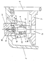
- the drawing shows a partial section through the machine or gear housing of an angle grinder in the area of the locking device.
- FIG. 1 is the gear housing here.
- a work spindle 2 is mounted, on which a ring gear 3 is rotatably mounted, which meshes with a motor pinion, not shown in the drawing.
- the ring gear is equipped with a plurality of notches 4 in the form of through holes which are axially parallel with the work spindle 2.
- the housing 1 has an indentation 5 which is directed inwards towards the ring gear 3.
- a guide sleeve 6 is inserted, which has a through opening 18 for guiding a locking bolt 7.
- the locking pin 7 is aligned with its axis on the flight circle of the locking recesses 4 of the ring gear 3 and with its enlarged diameter head 8 can dip into one of the locking recesses 4 with which the locking bolt 7 is then aligned coaxially.
- the locking pin 7 is shown in its unlocked position, in which it strikes with its stop collar 9 formed by the enlarged diameter of the head 8 on the inside of the wall of the machine housing 1 in the region of the indentation 5 or on the inner end face of the guide sleeve 6 .
- an actuation button 10 Coaxial with the locking pin 7 is an actuation button 10 which is guided in the mouth section 11 of the indentation 5 in the wall of the machine housing 1.
- the actuation button 10 has a coaxial bore 13, into which the locking pin 7 dips with its end 14 facing the actuation button.
- the locking pin 7 and the actuating button 10 are thus separate components, but are telescopically guided.
- an elastic connecting member 15 is supported in the form of a compression spring, which strives in the axial direction, the locking pin 7 and the operating button 10 spread apart.
- the expansion path is limited by a stop 16, which by a radially outwardly projecting collar at the end 14 of the locking pin 7 and a radially inwardly projecting collar is formed at the end 12 of the actuating button 10.
- a retaining spring 17, Coaxial with the locking bolt 7 and the actuating button 10 is a retaining spring 17, which is also designed as a compression spring.
- the retaining spring 17 is supported on the one hand on the outwardly facing end face of the guide sleeve 6 and on the other hand on an inwardly facing end face 20 of the actuating button 10, whereby the actuating button 10 in a non-depressed starting position in an over the outside of the machine housing 1 with its outer end above position is held.
- the actuating button 10 holds the locking pin 7 in its unlocked position, in which the ring gear 3 and thus the work spindle 2 can rotate freely with respect to the locking device.
- the actuating button 10 When depressed, the actuating button 10 moves with its inner end face 20 onto a radial shoulder 19 at the end of the mouth section 11 of the indentation 5 in the machine housing 1, the force of the retaining spring 17 having to be overcome.
- the telescopic path in the bore 13 of the operating button 10 for the end 14 of the locking pin 7 is greater than the displacement of the operating button 10, so that when the operating button 10 is depressed, the locking pin 7 does not strike the bottom of the bore 13 of the operating button 10. Rather, when the actuating button 10 is pressed, the connection to the locking pin 10 exists solely via the compression spring 15, which presses the locking pin 7 with its head 8 under a defined contact pressure against the opposite end face of the ring gear 3 with the locking recesses 4. In this way, snaps Reaching a certain outlet speed of the locking bolts 7 with its head 8 into one of the locking recesses 4 of the ring gear 3.
- the actuating button 10 springs back into its outer starting position under the force of the retaining spring 17, taking the locking pin 7 with it via the stop 16.
- the unlocking position is determined not only for the locking pin 7 but also via the stop 16 for the actuating button 10.
Landscapes
- Engineering & Computer Science (AREA)
- Mechanical Engineering (AREA)
- Finish Polishing, Edge Sharpening, And Grinding By Specific Grinding Devices (AREA)
- Constituent Portions Of Griding Lathes, Driving, Sensing And Control (AREA)
Applications Claiming Priority (2)
| Application Number | Priority Date | Filing Date | Title |
|---|---|---|---|
| DE4424022A DE4424022A1 (de) | 1994-07-08 | 1994-07-08 | Arretiervorrichtung für die Antriebsspindel von Handwerkzeugmaschinen |
| DE4424022 | 1994-07-08 |
Publications (2)
| Publication Number | Publication Date |
|---|---|
| EP0691180A2 true EP0691180A2 (fr) | 1996-01-10 |
| EP0691180A3 EP0691180A3 (fr) | 1996-06-05 |
Family
ID=6522591
Family Applications (1)
| Application Number | Title | Priority Date | Filing Date |
|---|---|---|---|
| EP95108463A Withdrawn EP0691180A3 (fr) | 1994-07-08 | 1995-06-02 | Système d'arrêt pour mandrin d'une machine à main |
Country Status (2)
| Country | Link |
|---|---|
| EP (1) | EP0691180A3 (fr) |
| DE (1) | DE4424022A1 (fr) |
Cited By (8)
| Publication number | Priority date | Publication date | Assignee | Title |
|---|---|---|---|---|
| EP0820838A1 (fr) * | 1996-07-25 | 1998-01-28 | Metabowerke GmbH & Co. | Ponçeuse à plateau excentrique |
| EP1066930A3 (fr) * | 1999-07-07 | 2002-02-06 | Black & Decker Inc. | Outil avec verouillage manuel de la broche |
| WO2003049907A1 (fr) * | 2001-12-06 | 2003-06-19 | Robert Bosch Gmbh | Machine-outil manuelle a arret de rotation de broche |
| EP1647366A1 (fr) * | 2004-10-15 | 2006-04-19 | A & M Electric Tools GmbH | Accouplement limiteur de couple pour un outil motorisé |
| US7988538B2 (en) | 2006-10-13 | 2011-08-02 | Black & Decker Inc. | Large angle grinder |
| CN105364788A (zh) * | 2014-08-19 | 2016-03-02 | 罗伯特·博世有限公司 | 手持式工具机 |
| EP3300835A1 (fr) * | 2016-09-29 | 2018-04-04 | Black & Decker Inc. | Accessoire de serrage et mécanisme de verrouillage de broche pour le verrouillage d'un outil électrique |
| US10792834B2 (en) | 2017-06-05 | 2020-10-06 | Milwaukee Electric Tool Corporation | Table saw |
Families Citing this family (1)
| Publication number | Priority date | Publication date | Assignee | Title |
|---|---|---|---|---|
| DE102012011702B4 (de) * | 2012-06-12 | 2025-04-30 | Ppr Gmbh | Bandschleifvorrichtung |
Family Cites Families (8)
| Publication number | Priority date | Publication date | Assignee | Title |
|---|---|---|---|---|
| US3872951A (en) * | 1973-11-06 | 1975-03-25 | Black & Decker Mfg Co | Spindle locking mechanism for rotary power device |
| DE3120899C2 (de) * | 1981-05-26 | 1983-10-27 | Licentia Patent-Verwaltungs-Gmbh, 6000 Frankfurt | Arretiervorrichtung für die Antriebsspindel von Winkelschleifern |
| DE3313704C2 (de) * | 1983-04-15 | 1985-05-09 | Metabowerke GmbH & Co, 7440 Nürtingen | Handwerkzeugmaschine, insbesondere Winkelschleifmaschine |
| DE8317913U1 (de) * | 1983-06-21 | 1984-11-29 | Robert Bosch Gmbh, 7000 Stuttgart | Vorrichtung zum arretieren der schleifspindel von winkelschleifern |
| DE3328955A1 (de) * | 1983-08-11 | 1985-02-21 | Robert Bosch Gmbh, 7000 Stuttgart | Winkelschleifer mit einer sicherheitskupplung |
| DE3603461A1 (de) * | 1986-02-05 | 1987-08-06 | Festo Kg | Arretiervorrichtung fuer eine werkzeugmaschine, insbesondere eine elektrische handwerkzeugmaschine |
| DE3741484C1 (de) * | 1987-12-08 | 1989-08-24 | Fein C & E | Handwerkzeugmaschine mit automatischer Arretierung der Arbeitsspindel |
| DE4100412A1 (de) * | 1991-01-09 | 1992-07-16 | Bosch Gmbh Robert | Elektrische handdrehwerkzeugmaschine, insbesondere handkreissaege |
-
1994
- 1994-07-08 DE DE4424022A patent/DE4424022A1/de not_active Ceased
-
1995
- 1995-06-02 EP EP95108463A patent/EP0691180A3/fr not_active Withdrawn
Non-Patent Citations (1)
| Title |
|---|
| None |
Cited By (14)
| Publication number | Priority date | Publication date | Assignee | Title |
|---|---|---|---|---|
| EP0820838A1 (fr) * | 1996-07-25 | 1998-01-28 | Metabowerke GmbH & Co. | Ponçeuse à plateau excentrique |
| EP1066930A3 (fr) * | 1999-07-07 | 2002-02-06 | Black & Decker Inc. | Outil avec verouillage manuel de la broche |
| US7052384B2 (en) | 2001-12-06 | 2006-05-30 | Robert Bosch Gmbh | Manual machine tool with spindle stop |
| WO2003049907A1 (fr) * | 2001-12-06 | 2003-06-19 | Robert Bosch Gmbh | Machine-outil manuelle a arret de rotation de broche |
| US8172003B2 (en) | 2004-10-15 | 2012-05-08 | Atlas Copco Electric Tools Gmbh | Overload protection device and machine tool having such overload protection device |
| EP1647366A1 (fr) * | 2004-10-15 | 2006-04-19 | A & M Electric Tools GmbH | Accouplement limiteur de couple pour un outil motorisé |
| US7988538B2 (en) | 2006-10-13 | 2011-08-02 | Black & Decker Inc. | Large angle grinder |
| US8388417B2 (en) | 2006-10-13 | 2013-03-05 | Black & Decker Inc. | Large angle grinder |
| CN105364788A (zh) * | 2014-08-19 | 2016-03-02 | 罗伯特·博世有限公司 | 手持式工具机 |
| CN105364788B (zh) * | 2014-08-19 | 2020-04-21 | 罗伯特·博世有限公司 | 手持式工具机 |
| EP3300835A1 (fr) * | 2016-09-29 | 2018-04-04 | Black & Decker Inc. | Accessoire de serrage et mécanisme de verrouillage de broche pour le verrouillage d'un outil électrique |
| US10682736B2 (en) | 2016-09-29 | 2020-06-16 | Black & Decker Inc. | Accessory clamp and spindle lock mechanism for power tool |
| US10792834B2 (en) | 2017-06-05 | 2020-10-06 | Milwaukee Electric Tool Corporation | Table saw |
| US11407142B2 (en) | 2017-06-05 | 2022-08-09 | Milwaukee Electric Tool Corporation | Table saw |
Also Published As
| Publication number | Publication date |
|---|---|
| DE4424022A1 (de) | 1996-01-18 |
| EP0691180A3 (fr) | 1996-06-05 |
Similar Documents
| Publication | Publication Date | Title |
|---|---|---|
| EP0344154B1 (fr) | Dispositif de fixation axiale d'un outil, notamment d'une meule | |
| DE19506708C1 (de) | Bohrvorrichtung | |
| DE2219658C3 (de) | Kraftgetriebenes Werkzeug | |
| DE3241528C2 (de) | Werkzeugspannfutter für einen Bohrhammer | |
| EP2448703B1 (fr) | Dispositif de perçage | |
| DE3414300C2 (fr) | ||
| EP2585241B1 (fr) | Machine-outil portative pourvue d'un mécanisme de percussion | |
| DE3422195C2 (de) | Schlagbohreinrichtung | |
| DE4445858A1 (de) | Bohrvorrichtung | |
| DE4100186A1 (de) | Handwerkzeugmaschine mit abnehmbaren werkzeughalter | |
| EP0345271A1 (fr) | Dispositif de serrage axial d'outils, en particulier de meules. | |
| CH692959A5 (de) | Vorrichtung zur Arretierung einer Welle. | |
| CH663375A5 (de) | Bohrfutter zum schlagbohren. | |
| EP0201662B1 (fr) | Mandrin pour forage rotatif ou forage rotatif avec percussion | |
| DE19521246B4 (de) | Stichsäge | |
| EP0691180A2 (fr) | Système d'arrêt pour mandrin d'une machine à main | |
| DE10024340C2 (de) | Stempel für Rundlaufpresse | |
| DE102019121049A1 (de) | Handgeführte Werkzeugmaschine, Baugruppe für eine Werkzeugmaschine sowie Adapterbuchse | |
| EP0194426B1 (fr) | Mandrin pour forage rotatif ou à percussion rotative | |
| DE102009034964B4 (de) | Spannfutter für eine Hand-Werkzeugmaschine | |
| DE202005011092U1 (de) | Rastriegel mit mittels Drehbewegung axial antreibbarem Raststift | |
| DE4439590A1 (de) | Handwerkzeugmaschine | |
| DE4102482A1 (de) | Handwerkzeugmaschine | |
| EP1533057B1 (fr) | Porte-outils pour un outil électrique, notamment pour une visseuse | |
| CH687914A5 (de) | Handwerkzeugmaschine. |
Legal Events
| Date | Code | Title | Description |
|---|---|---|---|
| PUAI | Public reference made under article 153(3) epc to a published international application that has entered the european phase |
Free format text: ORIGINAL CODE: 0009012 |
|
| AK | Designated contracting states |
Kind code of ref document: A2 Designated state(s): FR GB IT |
|
| PUAL | Search report despatched |
Free format text: ORIGINAL CODE: 0009013 |
|
| AK | Designated contracting states |
Kind code of ref document: A3 Designated state(s): FR GB IT |
|
| STAA | Information on the status of an ep patent application or granted ep patent |
Free format text: STATUS: THE APPLICATION IS DEEMED TO BE WITHDRAWN |
|
| 18D | Application deemed to be withdrawn |
Effective date: 19961206 |