EP0691292A2 - Machine de pulvérisation à rotor entraîné - Google Patents
Machine de pulvérisation à rotor entraîné Download PDFInfo
- Publication number
- EP0691292A2 EP0691292A2 EP95115850A EP95115850A EP0691292A2 EP 0691292 A2 EP0691292 A2 EP 0691292A2 EP 95115850 A EP95115850 A EP 95115850A EP 95115850 A EP95115850 A EP 95115850A EP 0691292 A2 EP0691292 A2 EP 0691292A2
- Authority
- EP
- European Patent Office
- Prior art keywords
- rotor
- machine
- plate
- bushes
- machine according
- Prior art date
- Legal status (The legal status is an assumption and is not a legal conclusion. Google has not performed a legal analysis and makes no representation as to the accuracy of the status listed.)
- Ceased
Links
- 238000005507 spraying Methods 0.000 title claims description 13
- 239000007921 spray Substances 0.000 claims description 6
- 230000005540 biological transmission Effects 0.000 claims description 5
- 238000002347 injection Methods 0.000 claims description 5
- 239000007924 injection Substances 0.000 claims description 5
- 238000001746 injection moulding Methods 0.000 claims description 3
- 230000000712 assembly Effects 0.000 abstract description 7
- 238000000429 assembly Methods 0.000 abstract description 7
- 238000007789 sealing Methods 0.000 description 24
- 238000010276 construction Methods 0.000 description 3
- 238000010586 diagram Methods 0.000 description 3
- 230000033001 locomotion Effects 0.000 description 2
- 239000000463 material Substances 0.000 description 2
- 230000007704 transition Effects 0.000 description 2
- 239000000654 additive Substances 0.000 description 1
- 239000000428 dust Substances 0.000 description 1
- 239000013013 elastic material Substances 0.000 description 1
- 238000007667 floating Methods 0.000 description 1
- 125000000524 functional group Chemical group 0.000 description 1
- 230000005484 gravity Effects 0.000 description 1
- 230000012447 hatching Effects 0.000 description 1
- 239000002184 metal Substances 0.000 description 1
- 210000000056 organ Anatomy 0.000 description 1
- 239000004576 sand Substances 0.000 description 1
- 238000000926 separation method Methods 0.000 description 1
- 230000001360 synchronised effect Effects 0.000 description 1
- 239000004636 vulcanized rubber Substances 0.000 description 1
- XLYOFNOQVPJJNP-UHFFFAOYSA-N water Substances O XLYOFNOQVPJJNP-UHFFFAOYSA-N 0.000 description 1
Images


Classifications
-
- B—PERFORMING OPERATIONS; TRANSPORTING
- B65—CONVEYING; PACKING; STORING; HANDLING THIN OR FILAMENTARY MATERIAL
- B65G—TRANSPORT OR STORAGE DEVICES, e.g. CONVEYORS FOR LOADING OR TIPPING, SHOP CONVEYOR SYSTEMS OR PNEUMATIC TUBE CONVEYORS
- B65G53/00—Conveying materials in bulk through troughs, pipes or tubes by floating the materials or by flow of gas, liquid or foam
- B65G53/34—Details
- B65G53/40—Feeding or discharging devices
- B65G53/46—Gates or sluices, e.g. rotary wheels
- B65G53/4608—Turnable elements, e.g. rotary wheels with pockets or passages for material
- B65G53/4616—Turnable elements, e.g. rotary wheels with pockets or passages for material with axis of turning parallel to flow
-
- B—PERFORMING OPERATIONS; TRANSPORTING
- B65—CONVEYING; PACKING; STORING; HANDLING THIN OR FILAMENTARY MATERIAL
- B65G—TRANSPORT OR STORAGE DEVICES, e.g. CONVEYORS FOR LOADING OR TIPPING, SHOP CONVEYOR SYSTEMS OR PNEUMATIC TUBE CONVEYORS
- B65G53/00—Conveying materials in bulk through troughs, pipes or tubes by floating the materials or by flow of gas, liquid or foam
- B65G53/32—Conveying concrete, e.g. for distributing same at building sites
Definitions
- the present invention relates to a spraying machine of the type specified in the preamble of claim 1.
- Such spraying machines usually have voluminous drive motors which are fixedly connected to the machine stator with their motor stator below the rotor stage and which drive the rotor stage with the motor rotor.
- the rotor stage is driven by means of a hydraulic hub motor, on the one hand the volume required for the rotor stage drive is significantly reduced, and in addition the stator which is centrally located in such motors allows, very simply, the outer rotor with the other parts of the rotor stage of the injection molding machine is connectable.
- the machine rotor with the bushes is preferably constructed as a module and as such can be easily detached from or connected to the hydraulic hub motor.
- a machine rotor in lightweight construction is preferably realized according to the wording of claim 3 in that it comprises separate upper and lower plate assemblies which are interconnected by at least a number of the sleeves.
- the bushings preferably have outer tubes and exchangeable inner tubes designed as wearing parts.
- an axially outer wear plate is preferably provided on the upper and lower plate arrangements, in accordance with the wording of claim 5, preferably in the form of a wear plate.
- a concrete spraying machine working according to the rotor principle is shown schematically. Concrete is poured into a hopper 1. Below the funnel 1, driven around an axis A, rotates a rotor 8 which, like a revolver, distributed around its circumference comprises a plurality of receiving bushings 7 for the concrete. A filling opening 6 is arranged in a fixed position on the funnel 1 such that, sequentially, the receiving bushes 7 are brought into alignment with the opening 6 when the rotor is rotated.
- a compressed air line 4 is provided, which is brought into operative connection via a compressed air opening 5 with respective bushes 7, thus brought into alignment.
- the respective sleeve 7 is aligned with an imposition opening 3 in the sealing plate 9.
- the sealing plate 9 closes, on the one hand, the respective sleeve 7 in the filling position and, on the other hand, provides for the imposition of the concrete filled into the respective bushing 7, tightness at the imposition opening 3 is ensured.
- An upper sealing plate 10 acts on the top of the rotor 8.
- the imposition opening 3 passes via a bend 11 into the delivery line, not shown here, of the concrete spraying machine, in which bend 11 a delivery pressure air line 13 opens.
- a driven agitator 15 acts in the funnel 1.
- Such a concrete spraying machine works according to the so-called "thin-flow principle", in which the spray medium, concrete, practically floating in the compressed air which is fed into line 13, is conveyed through the delivery line connected to the bend 11. Along this delivery line, water, possibly other additives, are also metered into the spray medium.
- FIG. 2 shows, in side view, a rotor-concrete spraying machine according to the invention, without the controls and drive units which are usually mounted on the same carriage.
- the essential functional groups on the machine according to the invention are to be presented, which are then to be described in more detail.
- the machine according to the invention comprises, as usual, a filling arrangement 20 with a filling funnel 21 with an agitator (not shown) and a vibrator. As was explained with reference to FIG. 1, the funnel 21 finally opens into the filling opening 6 for the rotor sleeves 7.
- the filling arrangement 20 is mounted on a device frame 25.
- the machine according to the invention further comprises a rotor stage 50, an upper stationary sealing arrangement 70 and one lower stationary sealing arrangement 80.
- the rotor stage 50 as well as the sealing arrangements 70 and 80 can, when viewed from above, be subdivided essentially into a low-pressure side ND and a high-pressure side HD by a diametrical plane E through the rotor axis A, perpendicular to the plane of FIG. 2.
- spray medium is filled into the rotor stage 50 through the filling arrangement 20, essentially under atmospheric pressure, while on the high-pressure side, as was explained with reference to FIG. 1, the spray medium is ejected from line 4 and line 13 by means of compressed air.
- the two areas ND and HD are indicated schematically in FIG. 2 by the hatching on both sides of the plane E by the rotor axis A.
- a tensioning arrangement 100 is also provided, by means of which, on the one hand, easy accessibility to the rotor stage 50 and the HD-side parts of the sealing arrangements 70, 80 is ensured, and with which, on the other hand, as will be explained later, the seals on the high-pressure side Rotor are ensured.
- the rotor stage 50 used on the machine according to the invention is simplified and partially shown in longitudinal section. It comprises a hydraulic hub motor 51, e.g. a "Poclain” motor, with a motor stator 55, as shown schematically at 53, rigidly connected to the device frame 25 (FIG. 2), formed by the motor axis.
- a hydraulic hub motor 51 e.g. a "Poclain” motor
- a motor stator 55 as shown schematically at 53, rigidly connected to the device frame 25 (FIG. 2), formed by the motor axis.
- Such hydraulic hub motors are from other applications known, are used for example for the single wheel drive of excavators. Their construction is extremely flat, as can easily be seen from the consideration of FIG. 3.
- the motor rotor 57 m rotating around the axis 55, carries the machine rotor 57 p, pre-assembled in accordance with the axial extent of the machine rotor 57 p .
- This is constructed from an upper rotor end plate 59, which is driven by the motor rotor 57 m via upper and lower connecting and torque transmission bolts 61.
- the arrangement of the upper transmission bolts 61 can also be seen from the rotor top view according to FIG. 4.
- bushings 7 are provided along the periphery of the machine rotor 57 p , as can be seen in FIG. 4, for example twelve. At least three of the provided bushings 7, designated as clamping bushes with 7a in FIGS. 3 and 4, form the mechanical holding connection to a lower rotor end plate 63. For this purpose these three bushes 7a are screwed to both the upper and the lower rotor end plates 59 and 59 respectively 63 screwed. The remaining bushes 7 are fixed between the plates 59 and 63 by means of the clamping bushes 7a mentioned.
- the machine rotor 57 p as a unitary assembly formed by the plates 59, 63 and the sleeves 7a and 7, can be removed in a modular manner by lifting off the transmission bolts 61 on the hub motor rotor 57 m .
- the machine rotor 57 p is extremely light and essentially only includes the components necessary for the function, which also enables the drive power to be reduced.
- the machine rotor 57 p is driven directly from the rotor 57 m of the hub motor via the bolts 61.
- the rotor sleeves 7, 7a do not transmit any torque, which enables the "lightweight construction" of the machine rotor 57 p .
- the machine rotor 57 p which can be removed as a single part, is shown in section in FIG. 5.
- the sleeves 7 and 7a are formed by outer tubes 8a and, inserted therein, insert sleeves 8b so that the latter, when exposed to the spray medium wear, can be easily replaced.
- FIG. 6 shows, enlarged, the upper end part of a bushing 7a, with outer tube 8a, insert bushing 8b and a closing clamping ring 8c for the insert bushing 8b.
- the bushing assembly is the same and, apart from the screw anchors 65, also on the other bushings 7.
- a wear plate 69 or 70 is advantageously placed both on the upper rotor end plate 59 and on the lower 63 and screwed to it (not shown).
- the compressed air opening 5 according to FIG. 1 is provided in the high pressure segment 71 HD .
- a substantially circular central web 72 with nozzle openings 73 is suspended in the compressed air opening 5, as can be seen in particular in FIG. This creates a nozzle-like transition.
- the plate 71 made of hard, vulcanized rubber, has on its upper side a metal cover plate 73, on which the web 72 is molded.
- the rotor movement with respect to the fixed plate 71 is entered with ⁇ R in FIG. 7 and in FIG. 8.
- the cover plate 73 is cut in the area of the compressed air opening 5, as shown at 74, and forms the spring bar 75, which can be seen in particular in FIG. 8 and extends into the plate.
- a stripping element 76 bent at the end in the shape of a semi-circle is welded onto it.
- the wiping element 76 is flush with the underside of the plate 71, ie with the plate surface in frictional engagement with the upper rotor surface, and, with the material of the plate 71 and the spring bar 75, resiliently mounted. This ensures a tight, self-adjusting application of the stripping element 76 on the upper rotor end face.
- the filling content of one of the rotor sleeves 7, 7a is imposed through the compressed air opening 5 via compressed air line 4. Due to the imposition taking place under high pressure, remains Further rotation of the rotor stage 50 in the direction ⁇ R , the rotor sleeve 7, 7a which has just been emptied to overpressure. For this reason, the compressed air opening 5 in the plate 71 is followed by a pressure relief opening 77, which communicates with the machine environment and through which pressure equalization takes place before the rotor sleeve under consideration reaches the low-pressure segment 71 ND of the plate 71.
- the filling opening 6 is provided in the form of a circular segment.
- a wiping element 76a is again provided at the end of the opening 6, attached and inserted into the plate 71 via webs 74a bent downward on the cover plate 73 according to FIG. 8, analogously to the element 76 at the compressed air opening 5.
- a lower, annular sealing plate 81 again made of elastic material, preferably rubber, is provided below the rotor stage 50, the lower sealing plate 81 also being subdividable into a high-pressure segment 81 HD and a low-pressure segment 81 ND . 1, aligned with the compressed air opening 5 according to FIG. 7.
- a stripping element 76 is provided, arranged and constructed at the imposition opening 3 like the stripping element 76 at the compressed air opening 5.
- FIG. 7 shows a top view of the upper sealing plate 71
- FIG. 9 shows a top view of the lower one and thus shows the stripping element 76 at the opening 3 exposed.
- the plate structure of the plate 81 with a cover plate 73 underneath is the same as the structure of the upper plate 71, except that there is neither a relief opening 77 on the lower plate 81 nor, as is readily apparent from FIG 1 results, a filling opening 6 is provided.
- FIG. 10 shows a top view of a machine according to the invention, with all the aggregates located above being removed for reasons of clarity.
- a very essential feature of the machine according to the invention can be seen from FIG. 10:
- the upper and lower sealing plates 71 and 81 are, as shown by T in FIGS. 7 and 9, in each of the two segments 71 HD , 71 ND ; 81 HD , 81 ND separately.
- the tensioning piston arrangements 102 with further organs which can be swung out with the tensioning arrangement 100, such as filter stage for the pressure equalization opening 77, connection 110 for the compressed air on line 4 of FIG. 1 etc., are mounted on a support frame 112.
- one of the two identically designed tensioning piston arrangements 102 is in the cocked position (a), in the relaxed and lowered position (b) and in the relaxed position lifted up and down (c). shown. The meaning of these positions will be explained.
- the piston rod 114 is a cylinder / piston arrangement 116 axially freely movable in a sliding bush 118.
- the cylinder of the piston / cylinder arrangement 116 supports the high-pressure side segment 71 HD of the plate 71 via a mounting plate 120 which, according to FIG. 10, carries both tensioning piston arrangements 102.
- the piston rod 114 in turn carries, again via a support plate 122, which is common to both tensioning piston arrangements 102 is provided, the high pressure segment 81 HD of the lower plate 81.
- a lower stop cam 126 for the piston rod 114 of the piston / cylinder arrangement 116 can be positioned with respect to the frame 112 and is in the tensioned position of the tensioning piston arrangement 102 according to FIG. 11 (a), viewed in the axial direction, spaced apart and below a stop surface 128 on the piston rod 114.
- the two tensioning piston arrangements 102 are each moved synchronously with their piston / cylinder arrangements 116, so that on the one hand the required sealing tension according to FIG. 11 (a) is reached on the rotor stage 50 11, (c), in which, according to FIG. 10, the entire high-pressure section of the tensioning device 100 on the device side can be folded out.
- the necessary sealing pressure can be optimized, irrespective of the sealing conditions on the low-pressure side section ND according to FIG. 10, in such a way that high surface pressures are only achieved on the HD segments where they are also necessary, on the high-pressure side.
- the seal conditions remain unaffected, corresponding to a much lower surface pressure required. This allows the power of the rotor drive motor, in particular the hub motor presented, to be reduced by more than half.
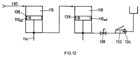
- FIG. 12 schematically shows the hydraulic diagram for the cylinder / piston arrangements 116 of the tensioning piston arrangements 102 according to FIG. 11.
- the two cylinders of the arrangements 116 are connected in series, the volume below the piston 116 a1 , taking into account the volume spanned by the piston rod 114, is the same size as the volume above the piston 116 a2 .
- System pressure for example 18 bar, is applied via line 130.
- the clamping piston assemblies is built up a high pressure by means of a hand pump 132, which both pistons 116 a are driven high in the cylinders exciting (Fig. 1).
- the same volumes mentioned ensure that both pistons 116 a cover the same clamping stroke.
- the high pressure built up by the hand pump 132 is released, for example by means of a manually operable valve 134, so that the two pistons 116 a run downward in line 130 due to the contact pressure and, according to FIG. 11, the rotor stage release.
- Mechanically operated check valves 136 of a known type are installed in each of the pistons 116 a .
- valve 136 on piston 116 a1 is opened mechanically, so that piston 116 a2 is also operated by the system pressure is driven into the stop position. In this way, synchronous motion of the pistons 116 a is repeatedly created if necessary.
- a manually operable ball valve 138 is preferably provided between the hand pump 132 and the relevant connection to one of the piston / cylinder arrangements 116.
Landscapes
- Engineering & Computer Science (AREA)
- Mechanical Engineering (AREA)
- Civil Engineering (AREA)
- Structural Engineering (AREA)
- On-Site Construction Work That Accompanies The Preparation And Application Of Concrete (AREA)
- Manufacture Of Motors, Generators (AREA)
- Nozzles (AREA)
Priority Applications (3)
| Application Number | Priority Date | Filing Date | Title |
|---|---|---|---|
| EP95115850A EP0691292A3 (fr) | 1995-10-09 | 1995-10-09 | Machine de pulvérisation à rotor entraîné |
| CA 2186298 CA2186298A1 (fr) | 1995-10-09 | 1996-09-24 | Vaporisateur a rotor entraine |
| JP26633496A JPH09187683A (ja) | 1995-10-09 | 1996-10-07 | ロータユニットを備えた吹き付け装置 |
Applications Claiming Priority (1)
| Application Number | Priority Date | Filing Date | Title |
|---|---|---|---|
| EP95115850A EP0691292A3 (fr) | 1995-10-09 | 1995-10-09 | Machine de pulvérisation à rotor entraîné |
Publications (2)
| Publication Number | Publication Date |
|---|---|
| EP0691292A2 true EP0691292A2 (fr) | 1996-01-10 |
| EP0691292A3 EP0691292A3 (fr) | 1996-05-08 |
Family
ID=8219695
Family Applications (1)
| Application Number | Title | Priority Date | Filing Date |
|---|---|---|---|
| EP95115850A Ceased EP0691292A3 (fr) | 1995-10-09 | 1995-10-09 | Machine de pulvérisation à rotor entraîné |
Country Status (3)
| Country | Link |
|---|---|
| EP (1) | EP0691292A3 (fr) |
| JP (1) | JPH09187683A (fr) |
| CA (1) | CA2186298A1 (fr) |
Families Citing this family (1)
| Publication number | Priority date | Publication date | Assignee | Title |
|---|---|---|---|---|
| JP4564153B2 (ja) * | 2000-09-29 | 2010-10-20 | 赤武エンジニアリング株式会社 | 粉体供給装置 |
Citations (1)
| Publication number | Priority date | Publication date | Assignee | Title |
|---|---|---|---|---|
| DE2415975A1 (de) * | 1974-04-02 | 1975-10-09 | Tsni I Pk I Prochodtscheskich | Rotor-schleusendosator fuer anlagen zur pneumatischen foerderung grobkoerniger gueter |
Family Cites Families (3)
| Publication number | Priority date | Publication date | Assignee | Title |
|---|---|---|---|---|
| US2299565A (en) * | 1942-02-02 | 1942-10-20 | Richard R Colburn | Pneumatic feeder |
| FR2482062A1 (fr) * | 1980-05-09 | 1981-11-13 | Ker France | Dispositif de stockage, de manutention et de distribution de materiaux pulverulents |
| DE4018770A1 (de) * | 1990-06-12 | 1991-12-19 | Fan Engineering Gmbh | Verfahren zur dosierten foerderung von dickfluessigen faserhaltigen suspensionen und vorrichtungen zur pumpengestaltung |
-
1995
- 1995-10-09 EP EP95115850A patent/EP0691292A3/fr not_active Ceased
-
1996
- 1996-09-24 CA CA 2186298 patent/CA2186298A1/fr not_active Abandoned
- 1996-10-07 JP JP26633496A patent/JPH09187683A/ja active Pending
Patent Citations (1)
| Publication number | Priority date | Publication date | Assignee | Title |
|---|---|---|---|---|
| DE2415975A1 (de) * | 1974-04-02 | 1975-10-09 | Tsni I Pk I Prochodtscheskich | Rotor-schleusendosator fuer anlagen zur pneumatischen foerderung grobkoerniger gueter |
Also Published As
| Publication number | Publication date |
|---|---|
| CA2186298A1 (fr) | 1997-04-10 |
| EP0691292A3 (fr) | 1996-05-08 |
| JPH09187683A (ja) | 1997-07-22 |
Similar Documents
| Publication | Publication Date | Title |
|---|---|---|
| DE19512993C2 (de) | Einheitliches Gehäuse für eine Doppelhydraulikeinheit | |
| EP1546489B1 (fr) | Pompe a beton mobile et bati de construction correspondant | |
| DE3142230C2 (de) | Einrichtung zur Leistungsanpassung eines Mehrzylinder-Kältemittelkompressors | |
| WO2009074395A1 (fr) | Cadre rapporté pour pompes à béton mobiles | |
| DE3120275C2 (de) | Brennkraftmaschine | |
| DE69905300T2 (de) | Hydraulische Steuereinheit, insbesondere für die Bedienung von einem Klappdach eines Fahrzeugs | |
| EP0767118B1 (fr) | Machine de pulvérisation à rotor entraíné | |
| DE102007063329B3 (de) | Werkzeug zum Zerkleinern von Koks | |
| EP0767119B1 (fr) | Joint à disque pour l'étanchéité d'une vanne rotative | |
| DE2508861C2 (de) | Hydraulische Antriebsvorrichtung mit einem Mitnehmerelemente aufweisenden Antriebskranz | |
| EP0209869B1 (fr) | Dispositif pour pivoter l'arbre d'un assemblage antidérapant à centrifuge de véhicules automobiles | |
| EP1076596A1 (fr) | Conteneur delivreur de materiau, en particulier pour pompes a substances epaisses | |
| DE102019007277A1 (de) | Konstantpumpe zur Verwendung zum Fördern eines Hydraulikfluids in einem geschlossenen Hydraulikkreislauf, geschlossener Hydraulikkreislauf, Baumaschine sowie Verfahren zum Betrieb einer Konstantpumpe in einem geschlossenen Hydraulikkreislauf | |
| DE2444464A1 (de) | Pumpvorrichtung zur foerderung von beton oder dergleichen plastischem material | |
| EP3942181B1 (fr) | Pompe mobile pour liquide épais | |
| EP1944511B1 (fr) | Conteneur destiné au chargement de matières pour pompe à matières hautement visqueuses | |
| DE2936669A1 (de) | Hydraulisches pumpenaggregat. | |
| EP0537561B1 (fr) | Dispositif de débouchage des tuyaux sanitaires | |
| DE102018110917A1 (de) | Exzenterschneckenpumpe | |
| EP4012176B1 (fr) | Dispositif de transport de matières épaisses | |
| EP0122299A1 (fr) | Moteur à pistons opposés | |
| EP0613995B1 (fr) | Moteur deux temps à piston | |
| DE2616249A1 (de) | Energieerzeugungseinrichtung | |
| DE2224074A1 (de) | Pumpe und Betätigungs- oder Steuereinrichtung | |
| DE2715686C3 (de) | Hubkolben-Viertakt-Brennkraftmaschine |
Legal Events
| Date | Code | Title | Description |
|---|---|---|---|
| PUAI | Public reference made under article 153(3) epc to a published international application that has entered the european phase |
Free format text: ORIGINAL CODE: 0009012 |
|
| AK | Designated contracting states |
Kind code of ref document: A2 Designated state(s): CH LI |
|
| PUAL | Search report despatched |
Free format text: ORIGINAL CODE: 0009013 |
|
| AK | Designated contracting states |
Kind code of ref document: A3 Designated state(s): CH LI |
|
| 17P | Request for examination filed |
Effective date: 19960327 |
|
| RAP1 | Party data changed (applicant data changed or rights of an application transferred) |
Owner name: SIKA EQUIPMENT AG |
|
| RAP3 | Party data changed (applicant data changed or rights of an application transferred) |
Owner name: SIKA EQUIPMENT AG |
|
| 17Q | First examination report despatched |
Effective date: 19970205 |
|
| GRAG | Despatch of communication of intention to grant |
Free format text: ORIGINAL CODE: EPIDOS AGRA |
|
| STAA | Information on the status of an ep patent application or granted ep patent |
Free format text: STATUS: THE APPLICATION HAS BEEN REFUSED |
|
| 18R | Application refused |
Effective date: 19990425 |