EP0691476A1 - Canal de pompage à courant tangentiel pour pompes turbomoléculaires - Google Patents
Canal de pompage à courant tangentiel pour pompes turbomoléculaires Download PDFInfo
- Publication number
- EP0691476A1 EP0691476A1 EP94202623A EP94202623A EP0691476A1 EP 0691476 A1 EP0691476 A1 EP 0691476A1 EP 94202623 A EP94202623 A EP 94202623A EP 94202623 A EP94202623 A EP 94202623A EP 0691476 A1 EP0691476 A1 EP 0691476A1
- Authority
- EP
- European Patent Office
- Prior art keywords
- rotor disk
- channel
- closure plate
- flow pumping
- tangential flow
- Prior art date
- Legal status (The legal status is an assumption and is not a legal conclusion. Google has not performed a legal analysis and makes no representation as to the accuracy of the status listed.)
- Granted
Links
- 238000005086 pumping Methods 0.000 title claims abstract description 44
- 238000013461 design Methods 0.000 abstract description 5
- 230000002093 peripheral effect Effects 0.000 description 5
- 238000012986 modification Methods 0.000 description 3
- 230000004048 modification Effects 0.000 description 3
- 230000002411 adverse Effects 0.000 description 1
- 238000004891 communication Methods 0.000 description 1
- 230000006835 compression Effects 0.000 description 1
- 238000007906 compression Methods 0.000 description 1
- 230000008878 coupling Effects 0.000 description 1
- 238000010168 coupling process Methods 0.000 description 1
- 238000005859 coupling reaction Methods 0.000 description 1
- 239000012530 fluid Substances 0.000 description 1
- 230000000149 penetrating effect Effects 0.000 description 1
- 238000011160 research Methods 0.000 description 1
- 238000012360 testing method Methods 0.000 description 1
Images
Classifications
-
- F—MECHANICAL ENGINEERING; LIGHTING; HEATING; WEAPONS; BLASTING
- F04—POSITIVE - DISPLACEMENT MACHINES FOR LIQUIDS; PUMPS FOR LIQUIDS OR ELASTIC FLUIDS
- F04D—NON-POSITIVE-DISPLACEMENT PUMPS
- F04D19/00—Axial-flow pumps
- F04D19/02—Multi-stage pumps
- F04D19/04—Multi-stage pumps specially adapted to the production of a high vacuum, e.g. molecular pumps
- F04D19/046—Combinations of two or more different types of pumps
Definitions
- the present invention relates to a tangential flow pumping channel of improved design for turbomolecular pumps.
- a tangential flow pumping channel utilizing one or more tangential flow pumping stages in conjunction with axial flow pumping stages.
- the cited '855 publication pertains to a turbomolecular pump which, in addition to conventional axial flow pumping stages, utilizes one or more tangential flow pumping stages, wherein the stator ring surrounding the rotor disk and the rotor disk surfaces are substantially parallel, thereby defining a pumping channel therebetween of substantially rectangular cross-section and uniform width.
- one of the advantages of the present invention is a tangential flow pumping channel of improved design, as part of one or more tangential flow pumping stages in an axial flow turbomolecular pump, which is designed to substantially improve the above-identified operational characteristics of said turbomolecular pump.
- a further advantage of the present invention is a pumping channel of improved design as an element of a turbomolecular pump which can be easily manufactured at a low cost.
- a turbomolecular pump comprising a tangential flow pumping stage and axial flow pumping stage wherein the tangential flow pumping stage has a flow channel located between an annular grooved inner wall of a stator and a lateral portion of a rotor disk.
- the lateral surface of the rotor disk may be grooved.
- the flow channel has a central portion defined by an upper and lower closure plates with a suction and discharge ports respectively, and a periphery portion defined by the lateral surface of the rotor disk and the annular grooved inner wall of the stator the suction and discharge ports operably coupled to the tangential flow channel.
- the tangential flow pump further comprising a baffle.
- the upper closure plate and a first plane surface of the rotor disk facing this upper plate defining a first region of close tolerance between discharge port and suction port while the lower closure plate and a second plane surface of the rotor disk opposed to the first one and facing the lower closure plate defining a second region of close tolerance between the discharge and suction ports.
- the baffle is protruded from the plates, extending into the groove of the rotor disk and forming a third region of close tolerance therewith.
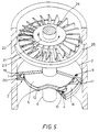
- FIG.1 and FIG.5 A first embodiment of the present invention is depicted in FIG.1 and FIG.5 , wherein a pumping channel 1 of circular cross-section is formed in a tangential pumping stage within the walls of a stator 2 , consisting of a first upper closure plate 3 and a second lower closure plate 4 , and having a rotor disk 5 secured to a shaft 6 and positioned between said upper closure plate 3 and lower closure plate 4 .
- the area between the upper and lower closure plates and the first upper plane and second lower plane surfaces of rotor disk 5 thereby defines a first and second region 7 and 8 respectively, of close tolerance between said closure plates and the rotor disk.
- Upper closure plate 3 and lower closure plate 4 are joined together by suitable means known to those skilled in the art, an example of which is shown in the figure which depict the coupling of downwardly extending edge 19 of upper closure plate 3 with the upwardly extending edge 20 ⁇ of lower closure plate 4 .
- the upper and lower closure plates are further provided with a suction port 9 and a discharge port 10 ⁇ respectively, both in fluid communication with channel 1 .
- the interior wall surface 13 formed by the junction of said plate edges 19 and 20 ⁇ , has a substantially semicircular internal perimeter thereby forming a circular passageway when cooperating with a substantially semicircular groove 12 provided in the peripheral edge of rotor disk 5 .
- Channel 1 is partially closed by baffle 18 which extends from plate edges 19 and 20 ⁇ between discharge port 10 ⁇ and suction port 9 counterclockwise, according to the direction of rotation of shaft 6 , as indicated by arrow 21 , wherein baffle 18 protrudes towards rotor disk 5 , thus penetrating into groove 12 and forming a third region of close tolerance 11 therewith.
- a pump housing 22 comprising, in addition to a tangential flow pumping stage having a pumping channel according to the present invention, an axial flow pumping stage 23 is provided, equipped with a vane rotor 24 and a vane stator 25 .
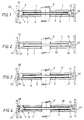
- FIG.2 there is shown a first modified embodiment of the present invention.
- a rotor 26 having a plane lateral surface for a peripheral edge, is provided instead of a rotor with a semicircular groove.
- the lateral surface thereby defines channel 32 of substantially semicircular cross-section rather than a channel of substantially circular cross-section as was provided in the previous embodiment.
- identical components have been given the same reference numerals as those shown in FIG.1 .
- V s and S are maximized by choosing a circular shape for the stationary part of the perimeter L, and V s is further increased by grooving the edge of the rotor as for example with a semicircular groove.
- a further consideration in the design of turbomolecular pumps regards the relative position of the moving surface of the rotor i.e., the peripheral wall with respect to stator wall. It is well known that the more the rotor penetrates the pumping channel, the more the value V s is increased, while conversely the less the rotor penetrates the pumping channel the more the channel cross-sectional area A increases. Based on these operational constraints it has been found that the best performances for the pumping of the present invention are achieved by utilizing a circular channel section obtained by means of a semicircular stator surface cooperating together with an opposing grooved rotor surface as disclosed above.
- FIGS. 3 and 4 embodiments are disclosed which are less expensive alternative solutions utilizing a partially optimized channel.
- a channel 27 of substantially semicircular cross-section obtained by means of a semicircular groove 12 in the peripheral wall of rotor 5 .
- the downwardly extending edge 28 of upper closure plate 30 ⁇ and the upwardly extending edge 29 of lower closure plate 31 in stator 15 provide for a substantially rectangular shape for internal surface 14 of channel 27 , thereby forming a semicircular pumping channel having a larger moving surface.
- FIG.4 there is shown still another embodiment of the present invention wherein rotor disk 17 is provided with a substantially rectangular groove 16 in its peripheral edge, thereby defining a channel 33 of substantially semicircular cross-section.
- identical components have been given the same reference numerals as those provided in FIG.3 .
Landscapes
- Engineering & Computer Science (AREA)
- Mechanical Engineering (AREA)
- General Engineering & Computer Science (AREA)
- Non-Positive Displacement Air Blowers (AREA)
Applications Claiming Priority (2)
| Application Number | Priority Date | Filing Date | Title |
|---|---|---|---|
| US08/265,542 US5449270A (en) | 1994-06-24 | 1994-06-24 | Tangential flow pumping channel for turbomolecular pumps |
| US265542 | 2002-10-03 |
Publications (2)
| Publication Number | Publication Date |
|---|---|
| EP0691476A1 true EP0691476A1 (fr) | 1996-01-10 |
| EP0691476B1 EP0691476B1 (fr) | 1997-12-10 |
Family
ID=23010889
Family Applications (1)
| Application Number | Title | Priority Date | Filing Date |
|---|---|---|---|
| EP94202623A Expired - Lifetime EP0691476B1 (fr) | 1994-06-24 | 1994-09-12 | Canal de pompage à courant tangentiel pour pompes turbomoléculaires |
Country Status (3)
| Country | Link |
|---|---|
| US (1) | US5449270A (fr) |
| EP (1) | EP0691476B1 (fr) |
| DE (2) | DE691476T1 (fr) |
Families Citing this family (2)
| Publication number | Priority date | Publication date | Assignee | Title |
|---|---|---|---|---|
| JPH09126178A (ja) * | 1995-10-27 | 1997-05-13 | Aisan Ind Co Ltd | 燃料ポンプ装置 |
| US6607351B1 (en) * | 2002-03-12 | 2003-08-19 | Varian, Inc. | Vacuum pumps with improved impeller configurations |
Citations (9)
| Publication number | Priority date | Publication date | Assignee | Title |
|---|---|---|---|---|
| GB336001A (en) * | 1929-07-09 | 1930-10-09 | Edwin Rodolph Grote | Improvements in pumps for obtaining high vacua |
| US1942139A (en) * | 1930-12-26 | 1934-01-02 | Central Scientific Co | Molecular vacuum pump |
| US1975568A (en) * | 1932-03-18 | 1934-10-02 | Central Scientific Co | Molecular vacuum pump |
| DE1063748B (de) * | 1955-04-29 | 1959-08-20 | Leybolds Nachfolger E | Kreiselpumpe zur Evakuierung von gasgefuellten Behaeltern |
| DE2034285A1 (de) * | 1970-07-10 | 1972-01-13 | Pfeiffer Vakuumtechnik | Molekularpumpe |
| DE3442843A1 (de) * | 1983-11-30 | 1985-06-05 | Hitachi, Ltd., Tokio/Tokyo | Vakuumpumpe |
| DE3932228A1 (de) * | 1988-09-28 | 1990-04-05 | Hitachi Ltd | Turbovakuumpumpe |
| EP0445855A1 (fr) * | 1990-03-09 | 1991-09-11 | VARIAN S.p.A. | Pompe turbomoléculaire améliorée |
| RU2001314C1 (ru) * | 1990-10-29 | 1993-10-15 | Алексей Валерьевич Федорук | Двухступенчатый компрессор |
Family Cites Families (3)
| Publication number | Priority date | Publication date | Assignee | Title |
|---|---|---|---|---|
| US5238362A (en) * | 1990-03-09 | 1993-08-24 | Varian Associates, Inc. | Turbomolecular pump |
| IT1250804B (it) * | 1991-07-10 | 1995-04-21 | Varian Spa | Stadio di pompaggio per pompa turbomolecolare |
| US5358373A (en) * | 1992-04-29 | 1994-10-25 | Varian Associates, Inc. | High performance turbomolecular vacuum pumps |
-
1994
- 1994-06-24 US US08/265,542 patent/US5449270A/en not_active Expired - Lifetime
- 1994-09-12 DE DE0691476T patent/DE691476T1/de active Pending
- 1994-09-12 EP EP94202623A patent/EP0691476B1/fr not_active Expired - Lifetime
- 1994-09-12 DE DE69407275T patent/DE69407275T2/de not_active Expired - Lifetime
Patent Citations (9)
| Publication number | Priority date | Publication date | Assignee | Title |
|---|---|---|---|---|
| GB336001A (en) * | 1929-07-09 | 1930-10-09 | Edwin Rodolph Grote | Improvements in pumps for obtaining high vacua |
| US1942139A (en) * | 1930-12-26 | 1934-01-02 | Central Scientific Co | Molecular vacuum pump |
| US1975568A (en) * | 1932-03-18 | 1934-10-02 | Central Scientific Co | Molecular vacuum pump |
| DE1063748B (de) * | 1955-04-29 | 1959-08-20 | Leybolds Nachfolger E | Kreiselpumpe zur Evakuierung von gasgefuellten Behaeltern |
| DE2034285A1 (de) * | 1970-07-10 | 1972-01-13 | Pfeiffer Vakuumtechnik | Molekularpumpe |
| DE3442843A1 (de) * | 1983-11-30 | 1985-06-05 | Hitachi, Ltd., Tokio/Tokyo | Vakuumpumpe |
| DE3932228A1 (de) * | 1988-09-28 | 1990-04-05 | Hitachi Ltd | Turbovakuumpumpe |
| EP0445855A1 (fr) * | 1990-03-09 | 1991-09-11 | VARIAN S.p.A. | Pompe turbomoléculaire améliorée |
| RU2001314C1 (ru) * | 1990-10-29 | 1993-10-15 | Алексей Валерьевич Федорук | Двухступенчатый компрессор |
Non-Patent Citations (1)
| Title |
|---|
| DATABASE WPI Section PQ 8 Week 9407, 6 April 1994 Derwent World Patents Index; Class Q56, AN 94-055220 * |
Also Published As
| Publication number | Publication date |
|---|---|
| DE69407275T2 (de) | 1998-04-02 |
| US5449270A (en) | 1995-09-12 |
| DE691476T1 (de) | 1996-10-10 |
| EP0691476B1 (fr) | 1997-12-10 |
| DE69407275D1 (de) | 1998-01-22 |
Similar Documents
| Publication | Publication Date | Title |
|---|---|---|
| US5527149A (en) | Extended range regenerative pump with modified impeller and/or housing | |
| EP0775828A1 (fr) | Pompes à vide turbo moléculaires | |
| US5813834A (en) | Centrifugal fan | |
| US4508492A (en) | Motor driven fuel pump | |
| EP0982502B1 (fr) | Compresseur centrifuge | |
| US6183196B1 (en) | Blower | |
| US4204802A (en) | Side channel compressor | |
| US6422808B1 (en) | Regenerative pump having vanes and side channels particularly shaped to direct fluid flow | |
| EP0445855B1 (fr) | Pompe turbomoléculaire améliorée | |
| US5607283A (en) | Westco-type fuel pump having improved impeller | |
| EP1361366B1 (fr) | Etage pour pompe à vide | |
| US4834612A (en) | In a pump wheel of a side-channel fuel pump | |
| US6779968B1 (en) | Side channel compressor | |
| JPH0642478A (ja) | 改良されたハウジング形状を有する液体リングポンプ | |
| EP0692636B1 (fr) | Etage de pompage convergent pour pompes turbomoléculaires | |
| EP0691476B1 (fr) | Canal de pompage à courant tangentiel pour pompes turbomoléculaires | |
| US7278822B2 (en) | Turbomolecular pump | |
| US4538968A (en) | Motor driven fuel pump | |
| EP0787903B1 (fr) | Pompe regénérative ayant des aubes et des canaux latéraux de forme particulière | |
| EP0159968A2 (fr) | Pompe pneumatique à palettes avec carter en tôle métallique estampée | |
| CN1079503C (zh) | 液体环式压缩机 | |
| CN209026962U (zh) | 压缩机以及应用该压缩机的空调器 | |
| JPH03550Y2 (fr) | ||
| JPS61142391A (ja) | 多段渦流ポンプ | |
| KR20010030770A (ko) | 유체기계, 유체기계의 플랜지 및 이들의 제조방법 |
Legal Events
| Date | Code | Title | Description |
|---|---|---|---|
| PUAI | Public reference made under article 153(3) epc to a published international application that has entered the european phase |
Free format text: ORIGINAL CODE: 0009012 |
|
| AK | Designated contracting states |
Kind code of ref document: A1 Designated state(s): DE FR GB IT |
|
| ITCL | It: translation for ep claims filed |
Representative=s name: INTERPATENT ST.TECN. BREVETTUALE |
|
| EL | Fr: translation of claims filed | ||
| 17P | Request for examination filed |
Effective date: 19960212 |
|
| 17Q | First examination report despatched |
Effective date: 19960423 |
|
| DET | De: translation of patent claims | ||
| GRAG | Despatch of communication of intention to grant |
Free format text: ORIGINAL CODE: EPIDOS AGRA |
|
| GRAH | Despatch of communication of intention to grant a patent |
Free format text: ORIGINAL CODE: EPIDOS IGRA |
|
| GRAH | Despatch of communication of intention to grant a patent |
Free format text: ORIGINAL CODE: EPIDOS IGRA |
|
| GRAA | (expected) grant |
Free format text: ORIGINAL CODE: 0009210 |
|
| AK | Designated contracting states |
Kind code of ref document: B1 Designated state(s): DE FR GB IT |
|
| REF | Corresponds to: |
Ref document number: 69407275 Country of ref document: DE Date of ref document: 19980122 |
|
| ET | Fr: translation filed | ||
| PLBE | No opposition filed within time limit |
Free format text: ORIGINAL CODE: 0009261 |
|
| STAA | Information on the status of an ep patent application or granted ep patent |
Free format text: STATUS: NO OPPOSITION FILED WITHIN TIME LIMIT |
|
| 26N | No opposition filed | ||
| REG | Reference to a national code |
Ref country code: FR Ref legal event code: TP |
|
| REG | Reference to a national code |
Ref country code: GB Ref legal event code: IF02 |
|
| PGFP | Annual fee paid to national office [announced via postgrant information from national office to epo] |
Ref country code: FR Payment date: 20100930 Year of fee payment: 17 |
|
| PGFP | Annual fee paid to national office [announced via postgrant information from national office to epo] |
Ref country code: GB Payment date: 20100927 Year of fee payment: 17 |
|
| PGFP | Annual fee paid to national office [announced via postgrant information from national office to epo] |
Ref country code: DE Payment date: 20100929 Year of fee payment: 17 |
|
| PGFP | Annual fee paid to national office [announced via postgrant information from national office to epo] |
Ref country code: IT Payment date: 20100928 Year of fee payment: 17 |
|
| REG | Reference to a national code |
Ref country code: FR Ref legal event code: TP Owner name: AGILENT TECHNOLOGIES INC, US Effective date: 20110823 |
|
| REG | Reference to a national code |
Ref country code: DE Ref legal event code: R082 Ref document number: 69407275 Country of ref document: DE Representative=s name: BARTELS & PARTNER, PATENTANWAELTE, DE |
|
| REG | Reference to a national code |
Ref country code: DE Ref legal event code: R082 Ref document number: 69407275 Country of ref document: DE Representative=s name: BARTELS UND PARTNER PATENTANWAELTE, DE Effective date: 20111130 Ref country code: DE Ref legal event code: R082 Ref document number: 69407275 Country of ref document: DE Representative=s name: BARTELS & PARTNER, PATENTANWAELTE, DE Effective date: 20111130 Ref country code: DE Ref legal event code: R081 Ref document number: 69407275 Country of ref document: DE Owner name: AGILENT TECHNOLOGIES INC., SANTA CLARA, US Free format text: FORMER OWNER: VARIAN, INC., PALO ALTO, CALIF., US Effective date: 20111130 Ref country code: DE Ref legal event code: R081 Ref document number: 69407275 Country of ref document: DE Owner name: AGILENT TECHNOLOGIES INC., US Free format text: FORMER OWNER: VARIAN, INC., PALO ALTO, US Effective date: 20111130 |
|
| GBPC | Gb: european patent ceased through non-payment of renewal fee |
Effective date: 20110912 |
|
| PG25 | Lapsed in a contracting state [announced via postgrant information from national office to epo] |
Ref country code: IT Free format text: LAPSE BECAUSE OF NON-PAYMENT OF DUE FEES Effective date: 20110912 |
|
| REG | Reference to a national code |
Ref country code: FR Ref legal event code: ST Effective date: 20120531 |
|
| REG | Reference to a national code |
Ref country code: DE Ref legal event code: R119 Ref document number: 69407275 Country of ref document: DE Effective date: 20120403 |
|
| PG25 | Lapsed in a contracting state [announced via postgrant information from national office to epo] |
Ref country code: DE Free format text: LAPSE BECAUSE OF NON-PAYMENT OF DUE FEES Effective date: 20120403 |
|
| PG25 | Lapsed in a contracting state [announced via postgrant information from national office to epo] |
Ref country code: GB Free format text: LAPSE BECAUSE OF NON-PAYMENT OF DUE FEES Effective date: 20110912 Ref country code: FR Free format text: LAPSE BECAUSE OF NON-PAYMENT OF DUE FEES Effective date: 20110930 |