EP0691484A1 - Kupplung, insbesondere für Diamantbohrkrone mit Schaftrohr und Rohrgewindeanschluss - Google Patents
Kupplung, insbesondere für Diamantbohrkrone mit Schaftrohr und Rohrgewindeanschluss Download PDFInfo
- Publication number
- EP0691484A1 EP0691484A1 EP95112857A EP95112857A EP0691484A1 EP 0691484 A1 EP0691484 A1 EP 0691484A1 EP 95112857 A EP95112857 A EP 95112857A EP 95112857 A EP95112857 A EP 95112857A EP 0691484 A1 EP0691484 A1 EP 0691484A1
- Authority
- EP
- European Patent Office
- Prior art keywords
- coupling
- tube
- parts
- clamping ring
- drill bit
- Prior art date
- Legal status (The legal status is an assumption and is not a legal conclusion. Google has not performed a legal analysis and makes no representation as to the accuracy of the status listed.)
- Granted
Links
Images


Classifications
-
- B—PERFORMING OPERATIONS; TRANSPORTING
- B28—WORKING CEMENT, CLAY, OR STONE
- B28D—WORKING STONE OR STONE-LIKE MATERIALS
- B28D1/00—Working stone or stone-like materials, e.g. brick, concrete or glass, not provided for elsewhere; Machines, devices, tools therefor
- B28D1/02—Working stone or stone-like materials, e.g. brick, concrete or glass, not provided for elsewhere; Machines, devices, tools therefor by sawing
- B28D1/04—Working stone or stone-like materials, e.g. brick, concrete or glass, not provided for elsewhere; Machines, devices, tools therefor by sawing with circular or cylindrical saw-blades or saw-discs
- B28D1/041—Working stone or stone-like materials, e.g. brick, concrete or glass, not provided for elsewhere; Machines, devices, tools therefor by sawing with circular or cylindrical saw-blades or saw-discs with cylinder saws, e.g. trepanning; saw cylinders, e.g. having their cutting rim equipped with abrasive particles
-
- E—FIXED CONSTRUCTIONS
- E21—EARTH OR ROCK DRILLING; MINING
- E21B—EARTH OR ROCK DRILLING; OBTAINING OIL, GAS, WATER, SOLUBLE OR MELTABLE MATERIALS OR A SLURRY OF MINERALS FROM WELLS
- E21B17/00—Drilling rods or pipes; Flexible drill strings; Kellies; Drill collars; Sucker rods; Cables; Casings; Tubings
- E21B17/02—Couplings; joints
- E21B17/04—Couplings; joints between rod or the like and bit or between rod and rod or the like
- E21B17/046—Couplings; joints between rod or the like and bit or between rod and rod or the like with ribs, pins, or jaws, and complementary grooves or the like, e.g. bayonet catches
-
- B—PERFORMING OPERATIONS; TRANSPORTING
- B23—MACHINE TOOLS; METAL-WORKING NOT OTHERWISE PROVIDED FOR
- B23B—TURNING; BORING
- B23B31/00—Chucks; Expansion mandrels; Adaptations thereof for remote control
- B23B31/02—Chucks
- B23B31/10—Chucks characterised by the retaining or gripping devices or their immediate operating means
- B23B31/113—Retention by bayonet connection
-
- F—MECHANICAL ENGINEERING; LIGHTING; HEATING; WEAPONS; BLASTING
- F16—ENGINEERING ELEMENTS AND UNITS; GENERAL MEASURES FOR PRODUCING AND MAINTAINING EFFECTIVE FUNCTIONING OF MACHINES OR INSTALLATIONS; THERMAL INSULATION IN GENERAL
- F16D—COUPLINGS FOR TRANSMITTING ROTATION; CLUTCHES; BRAKES
- F16D1/00—Couplings for rigidly connecting two coaxial shafts or other movable machine elements
- F16D1/10—Quick-acting couplings in which the parts are connected by simply bringing them together axially
- F16D1/108—Quick-acting couplings in which the parts are connected by simply bringing them together axially having retaining means rotating with the coupling and acting by interengaging parts, i.e. positive coupling
- F16D1/112—Quick-acting couplings in which the parts are connected by simply bringing them together axially having retaining means rotating with the coupling and acting by interengaging parts, i.e. positive coupling the interengaging parts comprising torque-transmitting surfaces, e.g. bayonet joints
Definitions
- the invention relates to a coupling for a linkage with power transmission, in particular for diamond core bits with a shaft tube and pipe thread connection.
- diamond core bits are known. In principle, they consist of a tube with diamonds, hard metals or the like fastened in a crown-like manner on one end face. They are used especially for drilling in rock and concrete. Depending on the application, they are operated in the wet or dry process.
- each coupling part has an end face arranged perpendicular to the axis and in which the two end faces are pressed together to achieve a tight and non-positive connection (DE-OS 86 03 499).
- the invention has for its object to provide an arrangement which enables a quick, easy connection of the rod parts with a light coupling arrangement and which does not undesirably affect the drilling process.
- FIG. 1 shows a perspective view of a diamond core bit 1 with a shaft tube 2 and a tube thread connection 3.
- the shaft tube 2 is provided on its one end face 4 in a crown-like manner with diamonds 5.
- These diamonds 5 can be used as pieces and soldered or can be provided as an admixture to a hardening filling compound forming the end face of the shaft tube.
- the end face can be provided with incisions for the passage of water.
- the shaft tube can also be provided with openings 7.
- the shaft tube 2 is provided with a shoulder 8, which forms a first coupling part. This approach is designed in such a way that it allows the liquid to pass into the shaft tube 2.
- a surface 9 is provided which is arranged essentially perpendicular to the axis of the switching tube 2.
- Grooves 12 are arranged diametrically opposite one another in the essentially cylindrical wall of the extension 8.
- the pipe thread connection 3 is also provided with a substantially cylindrical extension part 35, which serves as a second coupling part. From this part 35, two projections 11, for example bolts, protrude perpendicularly to the axial direction of the shaft tube. These projections 11 act together with the grooves 12.
- the cylindrical part 35 has an outer diameter and the extension 8 such that the part 35 can be pushed into the extension 8.
- the grooves 12 and the projections 11 are dimensioned so that the projections can engage in the grooves 12 and are guided by them.
- the outer wall of the part 35 and the inner wall are sealed against each other, for example by an o-ring 16 in an annular groove 17. In this way, the connection between the shaft tube 2 and the pipe thread connection 3 is sealed against the leakage of the coolant.
- the shaft tube 2 and the pipe thread connection 3 practically form a first and a second coupling part, both of which can be easily coupled by the projections 11 and the grooves 12.
- the coupling 2, 3 is such that the two parts 2, 3 are sealed at the same time by the seal 16 arranged between them when they are connected.
- the grooves 12 in part 8 have an input part 12a which initially runs approximately in the axial direction of the shaft tube 2 and then subsequently a guide part 12b which runs obliquely or perpendicularly to the axial direction.
- the direction of part 12b is selected so that the groove wall leads the projection 11 in the direction of a catch R when the parts 2, 3 to be coupled rotate.
- the detent R prevents the two parts 2, 3 thus assembled without receding again Rotate the parts again. If, for example, the pipe thread connection 3 is suspended in a fixed position, the shaft pipe 2, which is often very heavy, can be raised to the coupling and can be hung loosely into the coupling 3. In the same way, the loosely released coupling parts cannot fall apart, but are particularly lifted out of the connection and lowered.
- the extension 8 and the part 35 are first inserted into one another such that the protrusion (s) 11 engage in the groove parts 12a.
- the shaft tube 2 and the part 3 or 35 are then rotated relative to one another in such a way that the projections 11 move along the groove parts 12b until they reach the catch R as the end position.
- the detent R is achieved by extending the groove 12b in the axial direction. preferably in the direction of the surface 9.
- a clamping ring 25 can be displaced on the pipe thread connection part 3 in such a way that it pulls the projection 11 firmly into the catch R.
- part 3 is provided with an external thread and ring 25 with an internal thread.
- the mutually facing surfaces 9 of the neck 8 and 14 of the clamping ring 25 are arranged and dimensioned such that they are pressed firmly against one another and seal their connection.
- projections 91 are arranged in the direction of the other coupling part.
- the inner barge 141 is shaped or turned next to the surface 14. that the projections 91 can dip into the clamping ring 25 when the latter is twisted towards the projection 8 to clamp the surfaces 9, 14 or the bolts 11 in the grooves 12.
- the projections 91 and the corresponding shape 141 in the clamping ring enable the strength of the materials and dimensions used to be lower.
- a plastic is preferably used, as is already used as a bearing material. These are plastics that absorb little water and are easy to machine. During operation, high forces are transmitted through the clutch. Forces can cause the material to deform, for example radially, in the direction of the groove 12b or in the direction of the other coupling part.
- the two clamping surfaces 9 and 14 prevent deformations in the direction of the other coupling part, since the two surfaces are pressed against one another under great pressure. A deformation in the direction of the groove 12b or in the radial direction is prevented by the interaction of the projections 91 and 141 if the deformations exceed a predetermined amount. Then the two walls lie against each other.
- the outer diameter of the clamping ring 25 is dimensioned larger in the area of the surface 14 than it corresponds to the thickness of this clamping ring.
- FIG. 2 the sectional side view of a shaft tube 2 is shown with the attachment 8 inserted at one end and the coupled pipe thread connecting part 3. The seal 16 between the attachment 8 and the attachment part 35 is clearly visible.
- Fig. 3 shows the sectional side view of a clutch. Deviating from the coupling shown in FIG. 2, the projection 91 is formed here with an approximately trapezoidal profile.
- FIGS. 1-3 show a further development of the couplings according to FIGS. 1-3 for the transmission of particularly large forces.
- the plastic body 8 is surrounded by a thin metal sleeve 81 which increases durability, which is shrunk on and / or glued on.
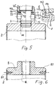
- FIG. 5 shows a coupling with depressions 93 in the coupling piece 8 carrying the grooves 12.
- These depressions 93 can be rectangular or trapezoidal and can be designed as individual depressions or as grooves. Grooves have proven to be particularly suitable. In the Grooves 93 engage burr-shaped projections 144 of the clamping ring 25. Care is also taken here that the walls of the projections and grooves do not touch one another without additional deformations after the coupling.
- the coupling described above with reference to the figures can be used as part of the drill pipes.
- the coupling parts can also be used as separate components in a variety of ways.
- a shaft tube 2 is shown with a coupling piece 8 which fits into the shaft tube 2, glued to it by means of a high-strength adhesive and is additionally connected by means of rivets 81 screws or the like.
- the coupling part 8 is provided with a thread 82, which is designed to accommodate conventional pipe connection threaded parts.
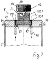
- FIG. 7 shows an embodiment of the coupling 8, in which a coupling part 82 is essentially disc-shaped and is firmly connected to the linkage 2 by shrinking and / or gluing and / or riveting or screwing.
- Linkage 2 of different diameters are provided with correspondingly adapted coupling parts 82.
- a bore with an internal thread 821 coaxial to the linkage is provided in the coupling part 82.
- a tubular coupling part 80 can be screwed into this threaded bore 821 and can be locked by means of a stop 87 and / or through bores 85 and bolts 86.
- the bores 85 penetrate both the threaded bore 821 and the coupling piece 80.
- the thread of the threaded bore is relatively steep and coarse in order to avoid seizing during operation with a large force transmission.
- the tubular coupling piece 80 protrudes with part of its length beyond the front end of the rod part 2 and can be coupled in this area with the coupling part 3 from FIG. 1.
- the coupling piece 80 is provided with grooves 12 and, if necessary, with a lawn position R for receiving the coupling part 3 with its projections 11.
- the outside of the coupling piece 80 is provided, at least in the area of the grooves 12, with a thread 801 onto which a ring 81 with a corresponding internal thread 811 can be screwed. This ring 81 therefore holds each turn of the thread 801 and stabilizes the edge area.
- the diameter of the ring 81 is selected so that it can be guided over the clutch 3 already installed.
- the parts 80, 801, 82, 83 and the ring 81 in FIG. 7 are made of a plastic, in particular a cast polyamide PA6 or PA6.6.
- the conical shape of the threads 801 and 811 simplifies the connection of the parts and speeds up the replacement process.
- the bolts 11 and 86 are preferably made of metal.
- the connecting pins 84 can be screws or rivets. Before the parts 2 and 82 are connected, the rod part 2 is heated and the end part 82 is cooled. After shrink-fitting, possibly in connection with a gluing of the adjacent surfaces and the mentioned rivets 84, this connection can also transmit very high forces.
- the parts which are effective for coupling are made of plastic, in particular of the materials mentioned above. Metals have only proven themselves for the tube 2 provided with the cutting elements and for the bolts 11. A substantial part of the advantages such as noise reduction and weight saving, as well as the safety associated with it during operation, is achieved by the disk 8 or 82 made of plastic inserted into the tube 2, which in particular with large diameters of the tubes 2 results in a stable position of the tool Drilling helps.
Landscapes
- Engineering & Computer Science (AREA)
- Mechanical Engineering (AREA)
- Mining & Mineral Resources (AREA)
- Geology (AREA)
- Life Sciences & Earth Sciences (AREA)
- General Life Sciences & Earth Sciences (AREA)
- Fluid Mechanics (AREA)
- Environmental & Geological Engineering (AREA)
- Physics & Mathematics (AREA)
- Geochemistry & Mineralogy (AREA)
- General Engineering & Computer Science (AREA)
- Earth Drilling (AREA)
- Mutual Connection Of Rods And Tubes (AREA)
- Drilling Tools (AREA)
- Processing Of Stones Or Stones Resemblance Materials (AREA)
- Soil Working Implements (AREA)
Abstract
Description
- Die Erfindung betrifft eine Kupplung für ein Gestänge mit Kraftübertragung, insbesondere für Diamantbohrkronen mit Schaftrohr und Rohrgewindeanschluß. Solche Diamantbohrkronen sind bekannt. Sie bestehen im Prinzip aus einem Rohr mit an einer Stirnseite kronenartig befestigten Diamanten, Hartmetallen oder dergleichen. Sie werden insbesondere zum Bohren in Gestein und Beton verwendet. Je nach Anwendungsbereich werden sie im Naß- oder Trockenverfahren betrieben.
- Es ist eine Kupplung für Gestänge mit Diamentbohrkronen mit Schaftrohr und Rohrgewindeanschluß bekannt, bei der jedes Kupplungsteil eine senkrecht zur Achse angeordnete Stirnfläche hat und bei der die beiden Stirnflächen zur Erzielung einer dichten und kraftschlüssigen Verbindung fest zusammengedrückt werden (DE-OS 86 03 499).
- Diese bekannte Kupplung hat sich zwar für den Bohrbetrieb bewährt, hat aber wegen der für die Festigkeit der Verbindung und die Kraftschlüssigkeit notwendigen hochfesten und korosionsstabilen Materialien ein relativ hohes Eigengewicht.
- Der Erfindung liegt die Aufgabe zugrunde, eine Anordnung zu schaffen, die mit leichter Kupplungsanordnung eine schnelle, einfache Verbindung der Gestängeteile ermöglicht und die den Bohrvorgang nicht unerwünscht beeinflußt.
- Diese Aufgabe wird bei einer Kupplung nach dem Oberbegriff des Anspruches 1 durch die im Kennzeichen des Anspruchs 1 gekennzeichnete Erfindung gelöst.
- Weiterbildungen der Erfindung sind in den Unteransprüchen gekennzeichnet.
- Zur näheren Erläuterung der Erfindung werden im folgenden Ausführungsbeispiele anhand der Zeichnungen beschrieben. Diese zeigen in
- Fig. 1 eine perspektivische Ansicht einer Diamantbohrkrone mit Schaftrohr und einer Kupplung zum Rohrgewindeanschluß
- Fig. 2 eine geschnittene Seitenansicht der miteinander verbundenen Teile gemäß Fig. 1
- Fig. 3 eine teilweise geschnittene Seitenansicht eines mit Nuten versehenen Kupplungsstükkes
- Fig. 4 eine andere Seitenansicht der zu kuppelnden Teile.
- Fig. 5 eine Kupplung mit Vertiefungen in dem mit Nuteri versehenen Kupplungsstück
- Fig. 6 ein Schaftrohr mit Schraubabschluß
- Fig. 7 eine Weiterbildung der Kupplung.
- In Fig. 1 ist in perspektivischer Darstellung eine Diamantbohrkrone 1 mit einem Schaftrohr 2 und einem Rohrgewindeanschluß 3 gezeigt. Das Schaftrohr 2 ist an seiner einen Stirnseite 4 kronenartig mit Diamanten 5 versehen. Diese Diamanten 5 können als Stücke eingesetzt und verlötet oder als Beimengung zu einer erhärtenden, die Stirnseite des Schaftrohres bildenden Füllmasse vorgesehen werden. Die Stirnseite kann mit Einschnitten für den Wasserdurchtritt versehen sein Außerdem kann das Schaftrohr noch mit Öffnungen 7 versehen sein. An der anderen Stirnseite ist das Schaftrohr 2 mit einem Ansatz 8 versehen, der ein erstes Kupplungsteil bildet. Dieser Ansatz ist so ausgebildet, daß er der Flüssigkeit den Durchlauf in das Schaftrohr 2 erlaubt, An der dem Schaftrohr 2 abgewandten Seite des Ansatzes 8 ist eine Fläche 9 vorgesehen, die im wesentlichen senkrecht zur Achse des Schaltrohres 2 angeordnet ist. In der im wesentlichen zylindrischen Wandung des Ansatzes 8 sind diametral gegenüberliegend Nuten 12 angeordnet. Der Rohrgewindeanschluß 3 ist ebenfalls mit einem im wesentlichen zylindrischen Ansatzteil 35 versehen, das als zweites Kupplungsteil dient. Aus diesem Teil 35 ragen senkrecht zur Achsrichtung des Schaftrohres 2 Vorsprünge 11, z.B. Bolzen hervor. Diese Vorsprünge 11 wirken zusammen mit den Nuten 12. Das zylindrische Teil 35 hat einen so bemessenen Außendurchmesser und der Ansatz 8 einen so bemessenen Innendurchmesser, daß das Teil 35 in den Ansatz 8 hineingeschoben werden kann. Die Nuten 12 und die Vorsprünge 11 sind so bemessen, daß die Vorsprünge in die Nuten 12 eingreifen können und von diesen geführt werden. Die Außenwandung des Teiles 35 und die Innenwandung sind gegeneinander abgedichtet, beispielsweise durch einen o-Ring 16 in einer ringförmigen Nut 17. Auf diese Weise wird die Verbindung von Schaftrohr 2 und Rohrgewindeanschluß 3 gegen den Austritt der Kühlflüssigkeit abgedichtet.
- Das Schaftrohr 2 und der Rohrgewindeanschluß 3 bilden praktisch ein erstes und ein zweites Kupplungsteil, die beide durch die Vorsprünge 11 und die Nuten 12 leicht kuppelbar sind. Die Kupplung 2,3 ist dabei so beschaffen, daß die beiden Teile 2,3 bei ihrer Verbindung zugleich durch die zwischen Ihnen angeordnete Dichtung 16 abgedichtet werden. Für die Erleichterung der Kupplung weisen die Nuten 12 im Teil 8 einen zunächst etwa in Achsrichtung des Schaftrohres 2 verlaufenden Eingangsteil 12a und dann anschließend einen schräg oder senkrecht zur Achsrichtung verlaufenden Führungs teil 12b auf. Die Richtung von Teil 12b ist so gewählt, daß die Nutwandung bei der Drehung der zu kuppelnden Teile 2,3 den Vorsprung 11 in Richtung auf eine Raste R führt. Die Raste R verhindert, daß sich die beiden so zusammengefügten Teile 2,3 ohne erneute rückläufige Drehung der Teile wieder lösen können. Wenn beispielsweise der Rohrgewindeanschluß 3 ortsfest aufgehängt ist, kann das oft sehr schwere Schaftrohr 2 zur Kupplung angehoben und lose in die Kupplung 3 eingehängt werden. In gleicher Weise können die locker gelösten Kupplungsteile nicht auseinanderfallen, sondern werden besonders aus der Verbindung herausgehoben und abgesenkt. Beim Zusammensetzen der Kupplungsteils 2,3 am Schaftrohr 2 und am Rohrgewindeansatz 3 werden zunächst der Ansatz 8 und das Teil 35 so ineinandergesteckt, daß der oder die Vorsprünge 11 in die Nutenteile 12a eingreifen. Anschließend werden das Schaftrohr 2 und das Teil 3 oder 35 so gegeneinander verdreht, daß sich die Vorsprünge 11 entlang der Nutenteile 12b bewegen bis sie als Endlage die Raste R erreichen. Die raste R wird durch eine Ausdehnung der Nute 12b in Achsrichtung erzielt. vorzugsweise in Richtung auf die Fläche 9. Zur Vollendung der Kupplung ist auf dem Rohrgewindeanschlußteil 3 ein Klemmring 25 so verschiebbar, daß er den Vorsprung 11 fest in die Raste R zieht. Zur Verschiebung ist das Teil 3 mit einem Außengewinde und der Ring 25 mit einem Innengewinde versehen. Die einander zugewandten Flächen 9 des Ansatzes 8 und 14 des Klemmrings 25 sind so angeordnet und bemessen, daß sie fest gegeneinander gedtückt werden und ihre Verbindung abdichten. Es ist aber auch möglich, ein Kupplungsteil ständig am Bohrgerät zu belassen und nur die diversen Schaftrohr auszuwechseln bzw. anzukuppeln. Die so geschaffene, kompakte und dichte Einheit wird in bekannter Weise mit dem Gewindeanschluß 18 des nur angedeuteten Bohrgerätes 19 verbunden. Nach dem Gebrauch werden das Schaftrohr 2 und der Rohrgewindeanschluß wieder voneinander durch Drehung der Teile getrennt. Die Trennung erfordert keine Werkzeuge. Zur Erleichterung der Trennung von evtl stärker verklemmten Teilen kann die Außenseite des Teiles 25 gerändelt sein oder andere Grifferleichterungen aufweisen. Außerdem kann eine Einfräsung F zum Ansetzen von Werkzeugen vorgesehen sein.
- Am Innenrand der Fläche 9 sind Vorsprünge 91 in Richtung auf das andere Kupplungsteil angeordnet. Im Klemmring 25 ist der Innenbareich 141 neben der Fläche 14 so geformt oder abgedreht. daß die Vorsprünge 91 in den Klemmring 25 eintauchen können, wenn dieser zur Verklemmung der Flächen 9, 14 bzw. der Bolzen 11 in den Nuten 12 auf den Ansatz 8 zu verddreht wird. Dabei soll zwischen den Vorsprüngen 91 und der Wandung 142 des Bereiches 141 gerade soviel Distanz bleiben, daß die Flächen 142 und 92 sich nicht ohne weiteres berühren. Dadurch wird erreicht, daß die Flächen 141 und 92 nicht zur Zentrierung der Kupplungsteile 2,3 beitragen und diese auch nicht ungünstig beeinflussen können, was beispielsweise geschehen könnte, wann die beiden Teile nicht mehr genau in Achsrichtung fluchten würden durch den Einfluß der beiden Wandungen 92, 142.
- Die Vorsprünge 91 und die entsprechende Form 141 im Klemmring ermöglichen eine geringere Festigkeit der verwendeten Materialien und Abmessungen. Es wird dadurch möglich, statt eines hochfesten Stahls Keramik oder Kunststoff, beispielsweise glasfaserverstärkten Kunststoff GFK oder ein Polyamid der Typen PA 6 oder PA 6,6 oder einen polykristallinen Kunststoff zu verwenden. Vorzugsweise wird ein Kunststoff eingesetzt, wie er bereits als Lagerwerkstoff Verwendung findet. Das sind Kunststoffe, die wenig Wasser aufnehmen und leicht bearbeitbar sind. Während des Betriebes werden über die Kupplung hohe Kräfte übertragen. Dabei können Kräfte eine Verformung des Materials bewirken, beispielsweise radial, in Richtung der Nute 12b oder in Richtung auf das andere Kupplungsteil. Durch die beiden Klemmflächen 9 und 14 werden Verformungen in Richtung auf das andere Kupplungsteil verhindert, da die beiden Flächen unter großem Druck gegeneinander gepreßt werden. Eine Verformung in Richtung der Nute 12b oder in radialer Richtung wird durch die Zusammenwirkung der Vorsprünge 91 und 141 unterbunden, wenn die Verformungen ein vorbestimmtes Maß übersteigen. Dann nämlich liegen die beiden Wandungen gegeneinander.
- Um die Wirksamkeit der gegeneinandergedrückten Stirnflächen 9 und 14 zu erhöhen, werden diese Flächen so groß wie möglich gemacht. Zu diesem Zweck wird der Außendurchmesser des Klemmrings 25 im Bereich der Fläche 14 größer bemessen als es der Dicke dieses Klemmrings entspricht.
- In Fig. 2 ist die geschnittene Seitenansicht eines Schaftrohres 2 mit dem an einem Ende eingesetzten Ansatz 8 und dem angekuppelten Rohrgewindeanschlußteil 3 dargestellt. Deutlich sichtbar ist die Dichtung 16 zwischen dem Ansatz 8 und dem Ansatzteil 35.
- Fig. 3 zeigt die geschnittene Seitenansicht einer Kupplung. Abweichend von der in Fig. 2 dargestellten Kupplung ist hier der Vorsprung 91 mit einem etwa trapezförmigen Profil ausgebildet.
- In Fig. 4 ist eine Weiterbildung der Kupplungen nach Fig. 1 - Fig. 3 für die Übertragung besonders großer Kräfte dargestellt. Bei dieser Weiterbildung ist der Kunststoffkörper 8 von einer dünnen, die Haltbarkeit steigernden Metallhülse 81 umgeben, die aufgeschrumpft und/oder aufgeklebt ist.
- Fig. 5 zeigt eine Kupplung mit Vertiefungen 93 in dem die Nuten 12 tragenden Kupplungsstück 8. Diese Vertiefungen 93 können rechteckförmig oder trapezförmig ausgebildet sein und als einzeine Vertiefungen oder als Nuten ausgebildet sein. Nuten haben sich als besonders geeignet erwiesen. In die Nuten 93 greifen gratförmige Vorsprünge 144 des Klemmrings 25 ein. Auch hier ist dafür Sorge getragen, daß die Wandungen der Vorsprünge und Nuten sich ohne zusätzliche Verformungen nach der Verkupplung nicht berühren.
- Die vorstehend anhand der Figuren beschriebene Kupplung kann als Teil der Gestängerohre verwendet werden. Die Kupplungsteile können aber auch als gesonderte Bauteile vielseitig eingesetzt werden.
- In Fig. 6 ist ein Schaftrohr 2 mit einem Kupplungsstück 8 dargestellt, das in das Schaftrohr 2 eingepaßt, mit diesem mittels eines hochfesten Klebers verklebt und zusätzlich mittels Nieten 81. Schrauben oder dergl.verbunden ist. Das Kupplungsteil 8 ist mit einem Gewinde 82 versehen, das zur Aufnahme üblicher Rohranschlußgewindeteile ausgebildet ist.
- Die Verwendung der Kupplungsteile aus Kunststoff führt zu einer wesentlichen Verringerung der Bohrgeräusche.
- In Fig. 7 ist ein Ausführungsbeispiel der Kupplung 8 dargestellt, bei dem ein Kupplungsteil 82 im wesentlichen scheibenförmig ausgebildet und durch Aufschrumpfen und/oder Kleben und/oder Vernieten oder Verschrauben mit dem Gestänge 2 fest verbunden ist. Gestänge 2 unterschiedlicher Durchmesser sind mit entsprechend angepaßten Kupplungsteilen 82 versehen. Im Kupplungsteil 82 ist eine zum Gestänge koaxiale Bohrung mit Innengewinde 821 vorgeshen. In diese Gewindebohrung 821 ist ein rohrförmiges Kupplungsteil 80 einschraubbar und mittels eines Anschlages 87 und/oder durch Bohrungen 85 und Bolzen 86 arretierbar. Die Bohrungen 85 durchdringen sowohl die Gewindebohrung 821 als auch das Kupplungsstück 80. Das Gewinde der Gewindebohrung ist relativ steil und grob, um ein Festfressen während des Betriebes mit großer Kraübertragung zu vermeiden.
- Das rohrförmige Kupplungsstück 80 ragt mit einem Teil seiner Länge über den stirnseitigen Abschluß des Gestängeteils 2 hinaus un ist in diesem Bereich mit dem Kupplungsteil 3 aus Fig. 1 kuppelbar. Das Kupplungsstück 80 ist mit Nuten 12 und ggf mit einer Rasstellung R für die Aufnahme des Kupplungsteiles 3 mit seinen Vorsprüngen 11 versehen. Um eine Verformung des durch die Nuten 12 oder dergl geschwächten Randbereichs des Kupplungsstückes zu vereiden, ist die Außenseite des Kupplungsstückes 80 wenigstens im Bereich dar Nuten 12 mit einem Gewinde 801 versehen, auf das ein Ring 81 mit entsprechendem Innengewinde 811 aufschraubbar ist. Dieser Ring 81 gibt daddurch jeder Windung des Gewindes 801 Halt und bewirkt eine Stabilisierung des Randbereichs. Der Durchmesser des Ringes 81 ist so gewählt, daß er über die bereits eingebaute Kupplung 3 geführt werden kann.
- Die Teile 80, 801, 82, 83 sowie der Ring 81 in Fig. 7 sind aus einem Kunststoff, insbesondere aus einem Gußpolyamid PA6 oder PA6,6 gefertigt. Durch kegelförmige Ausbildung der Gewinde 801 und 811 läßt sich die Verbindung der Teile vereinfachen und das Auswechselverfahren beschleunigen. Die Bolzen 11 und 86 sind vorzugsweise aus Metall gefertigt. Die Verbindungsstifte 84 können Schrauben oder Nieten sein. Vor der Verbindung der Teile 2 und 82 wird das Gestängeteil 2 erhitzt und das Abschlußteil 82 gekühlt. Nach dem Aufschrumpfen ggf in Verbindung mit einem Verkleben der benachbarten Flächen und den genannten Nieten 84 kann diese Verbindung auch sehr hohe Kräfte übertragen.
- Bei einer bevorzugten Ausführungsform der Kupplung sind die für das Kuppeln wirksamen Teile aus Kunststoff, insbesondere der vorstehend genannten Materialien, gefertigt. Lediglich für das mit den Schneidelementen versehene Rohr 2 und für die Bolzen 11 haben sich Metalle bewährt. Ein wesentlicher Teil der dadurch bewirkten Vorteile wie Geräuschverringerung und Gewichtsersparnis sowie die beim Betrieb damit verbundene Sicherheit wird durch die in das Rohr 2 eingesetzte Scheibe 8 bzw. 82 aus Kunststoff erzielt, die insbesondere bei großen Durchmessern der Rohre 2 zu einer stabilen Lage des Werkzeugs beim Bohren beiträgt.
Claims (10)
- Kupplung für Bohrgestänge mit Kraftübertragung von einer Bohrmaschine auf eine Bohrkrone mit zwei zu kuppelnden Kupplungsteilen (3,8), dadurch gekennzeichnet, daß das eine, Nuten aufweisende Kupplungsteil (8) und/oder das eine, Vorsprünge (11) aufweisende Kupplungsstück (3) und/oder das mit einem die Bohrkrone tragenden Rohr (2) an dem der Bohrkrone abgewandten Ende zu einer Einheit verbundene Kupplungsteil (8) und/oder ein die Kupplungsteile (3, 8) kraftschlüssig verbindender Klemmring (25) ganz oder teilweise aus einem leichten Nichteisenmaterial besteht.
- Kupplung nach Anspruch 1, dadurch gekennzeichnet, daß das Material Kunststoff ist.
- Kupplung nach Anspruch 1, dadurch gekennzeichnet, daß das Material ein glasfaserverstärkter Kunststoff ist.
- Kupplung nach Anspruch 1, dadurch gekennzeichnet, daß das Material ein Polyamid ist.
- Kupplung nach Anspruch 1, dadurch gekennzeichnet, daß das Material polykristallin ist.
- Kupplung nach Anspruch 1, dadurch gekennzeichnet, daß die Kupplungsteile (3,8) durch den Klemmring (25) miteinander kraftschlüssig verbindbar sind.
- Kupplung nach einem der Ansprüche 1 - 6, dadurch gekennzeichnet, daß Rohr (2) und Kupplungsteil (8) mittels eines Klebers verbunden sind.
- Kupplung nach einem der Ansprüche 1 - 7, dadurch gekennzeichnet, daß Rohr (2) und Kupplungsteil (8) durch Aufschrumpfen verbunden sind.
- Kupplung nach einem der Ansprüche 1 - 8, dadurch gekennzeichnet, daß Rohr (2) und Kupplungsteil (8) durch Nieten miteinander verbunden sind.
- Kupplung nach Anspruch 4, dadurch gekennzeichnet, daß das Material ein Polyamid der Type PA6 oder PA 6,6 ist.
Applications Claiming Priority (5)
| Application Number | Priority Date | Filing Date | Title |
|---|---|---|---|
| DE3736302 | 1987-10-27 | ||
| DE19873736302 DE3736302A1 (de) | 1987-10-27 | 1987-10-27 | Kupplung, insbesondere fuer diamantbohrkrone mit schaftrohr und rohrgewindeanschluss |
| DE3813472 | 1988-04-21 | ||
| DE3813472A DE3813472A1 (de) | 1988-04-21 | 1988-04-21 | Kupplung, insbesondere fuer diamantbohrkrone mit schaftrohr und rohrgewindeanschluss |
| EP88117893A EP0314123B1 (de) | 1987-10-27 | 1988-10-27 | Kupplung, insbesondere für Diamantbohrkrone mit Schaftrohr und Rohrgewindeanschluss |
Related Parent Applications (2)
| Application Number | Title | Priority Date | Filing Date |
|---|---|---|---|
| EP88117893.3 Division | 1988-10-27 | ||
| EP88117893A Division EP0314123B1 (de) | 1987-10-27 | 1988-10-27 | Kupplung, insbesondere für Diamantbohrkrone mit Schaftrohr und Rohrgewindeanschluss |
Publications (2)
| Publication Number | Publication Date |
|---|---|
| EP0691484A1 true EP0691484A1 (de) | 1996-01-10 |
| EP0691484B1 EP0691484B1 (de) | 2001-01-10 |
Family
ID=25861152
Family Applications (2)
| Application Number | Title | Priority Date | Filing Date |
|---|---|---|---|
| EP95112857A Expired - Lifetime EP0691484B1 (de) | 1987-10-27 | 1988-10-27 | Kupplung für Bohrgestänge mit Kraftübertragung auf eine Bohrkrone |
| EP88117893A Expired - Lifetime EP0314123B1 (de) | 1987-10-27 | 1988-10-27 | Kupplung, insbesondere für Diamantbohrkrone mit Schaftrohr und Rohrgewindeanschluss |
Family Applications After (1)
| Application Number | Title | Priority Date | Filing Date |
|---|---|---|---|
| EP88117893A Expired - Lifetime EP0314123B1 (de) | 1987-10-27 | 1988-10-27 | Kupplung, insbesondere für Diamantbohrkrone mit Schaftrohr und Rohrgewindeanschluss |
Country Status (5)
| Country | Link |
|---|---|
| EP (2) | EP0691484B1 (de) |
| AT (2) | ATE136094T1 (de) |
| DE (2) | DE3855151D1 (de) |
| DK (1) | DK597088A (de) |
| ES (1) | ES2156175T3 (de) |
Cited By (12)
| Publication number | Priority date | Publication date | Assignee | Title |
|---|---|---|---|---|
| EP0791721A1 (de) * | 1996-02-20 | 1997-08-27 | Schlumberger Limited | Vorrichtung und Verfahren zum Bohren mit einer flexiblen Welle |
| WO1998010881A1 (en) * | 1996-09-13 | 1998-03-19 | Seco Tools Ab (Publ) | Tool for cutting machining |
| WO1998024606A1 (de) * | 1996-12-06 | 1998-06-11 | Delco Imperial Establishment | Hohlbohrwerkzeug, insbesondere diamantbohrwerkzeug |
| GB2324486A (en) * | 1997-04-24 | 1998-10-28 | Marcrist Ind Ltd | Masonry core-cutting tool |
| GB2305678B (en) * | 1995-09-27 | 1999-11-17 | Baker Hughes Inc | Drill pipe float valve |
| EP1083292A1 (de) * | 1999-09-10 | 2001-03-14 | Earth Tool Company L.L.C. | System mit auswechselbarem Bohrmeissel zum Richtungsbohren |
| EP1275459A1 (de) * | 2001-07-12 | 2003-01-15 | Toolmatic BVBA | Saugkopf, Verlängerung und Werkzeug zum Trockenbohren |
| US7371034B2 (en) | 2002-06-06 | 2008-05-13 | John Clark | Drilling attachment |
| JP2016502007A (ja) * | 2012-12-21 | 2016-01-21 | ヒルティ アクチエンゲゼルシャフト | 冠状ドリルビット用切削部 |
| CN105829750A (zh) * | 2013-12-16 | 2016-08-03 | 利莱森玛电机公司 | 用于联接驱动机与从动机的系统 |
| CN111894969A (zh) * | 2020-07-20 | 2020-11-06 | 邹城兖矿泰德工贸有限公司 | 强力型接杆 |
| GB2594342A (en) * | 2020-04-23 | 2021-10-27 | Plumbingenuity Ltd | Tool |
Families Citing this family (12)
| Publication number | Priority date | Publication date | Assignee | Title |
|---|---|---|---|---|
| FI115661B (fi) | 2002-12-23 | 2005-06-15 | Robit Rocktools Ltd | Teräsovitelma |
| DE102007019168A1 (de) | 2007-04-20 | 2008-10-23 | Geißler & Kuper GmbH Diamantwerkzeuge, Maschinen | Bohreinrichtung |
| WO2012154102A1 (en) * | 2011-05-04 | 2012-11-15 | Pct-Systems Ab | Method to safely become a skillful user during use of an interactive pipe cleaning equipment comprising a machine having one in a fixed cover rotating flexible shaft and a machine to perform said method |
| DE102011089546A1 (de) | 2011-12-22 | 2013-06-27 | Hilti Aktiengesellschaft | Bohrkrone mit einem austauschbaren Bohrkronenabschnitt |
| CN103697074A (zh) * | 2014-01-04 | 2014-04-02 | 陈焕祥 | 一种电机搅拌接头 |
| DE102015100922A1 (de) * | 2015-01-22 | 2016-07-28 | Newfrey Llc | Wechselmatrize, Fügewerkzeug und Fügeverfahren |
| EP3184219A1 (de) | 2015-12-22 | 2017-06-28 | HILTI Aktiengesellschaft | Bohrkrone |
| EP3184215A1 (de) | 2015-12-22 | 2017-06-28 | HILTI Aktiengesellschaft | Set aus mehreren bohrschaftabschnitten zum aufbau einer bohrkrone |
| EP3184218A1 (de) | 2015-12-22 | 2017-06-28 | HILTI Aktiengesellschaft | Set aus mehreren bohrkronenabschnitten zum aufbau einer bohrkrone |
| CN108798576B (zh) * | 2018-07-20 | 2023-11-10 | 广东鸿翔工程检测咨询有限公司 | 一种公路路面检测用钻孔取芯机 |
| IT201900011766A1 (it) * | 2019-07-15 | 2021-01-15 | Algra S P A | Dispositivo per la stabilizzazione controllata di codoli portautensili |
| CN110821945B (zh) * | 2019-11-07 | 2020-11-17 | 北京航空航天大学 | 一种中空传动轴内嵌液路旋转接头与中空传动轴连接件 |
Citations (4)
| Publication number | Priority date | Publication date | Assignee | Title |
|---|---|---|---|---|
| GB2065759A (en) * | 1979-12-14 | 1981-07-01 | Itt | Bayonet soupling nut |
| DE8627861U1 (de) * | 1986-10-18 | 1986-12-18 | Geißler & Kuper GmbH Diamantwerkzeug - Wiederaufbereitung, 3100 Celle | Rohrgestänge, insbesondere für Diamantbohrkronen |
| EP0235581A1 (de) * | 1986-02-05 | 1987-09-09 | Geissler & Kuper GmbH Diamantwerkzeug-Wiederaufbereitung | Kupplung, insbesondere für Diamantbohrkrone mit Schaftrohr und Rohrgewindeanschluss |
| DE8603499U1 (de) | 1986-02-10 | 1990-08-02 | Thyssen Industrie AG Schmiedetechnik/Bergbautechnik, 4100 Duisburg | Balkengleisbremse für schienengebundene Fahrzeuge |
Family Cites Families (5)
| Publication number | Priority date | Publication date | Assignee | Title |
|---|---|---|---|---|
| US2240738A (en) * | 1937-07-14 | 1941-05-06 | Nat Supply Co | Rotary drilling rig |
| DE1097929B (de) * | 1960-01-25 | 1961-01-26 | Mannesmann Ag | Rohrverbindung fuer die Gestaengerohre eines Erdbohrers mit Vorortantrieb |
| BE660158A (de) * | 1965-02-24 | 1965-08-24 | ||
| US4072441A (en) * | 1976-04-15 | 1978-02-07 | Parker Manufacturing Company | Hole saw |
| DE3412249A1 (de) * | 1984-04-02 | 1985-10-10 | Witte Bohrtechnik GmbH, 3060 Stadthagen | Vortriebsrohrsatz fuer den unterirdischen rohrvortrieb |
-
1988
- 1988-10-27 EP EP95112857A patent/EP0691484B1/de not_active Expired - Lifetime
- 1988-10-27 DE DE3855151T patent/DE3855151D1/de not_active Expired - Fee Related
- 1988-10-27 AT AT88117893T patent/ATE136094T1/de active
- 1988-10-27 DK DK597088A patent/DK597088A/da not_active Application Discontinuation
- 1988-10-27 AT AT95112857T patent/ATE198638T1/de not_active IP Right Cessation
- 1988-10-27 ES ES95112857T patent/ES2156175T3/es not_active Expired - Lifetime
- 1988-10-27 EP EP88117893A patent/EP0314123B1/de not_active Expired - Lifetime
- 1988-10-27 DE DE3856454T patent/DE3856454D1/de not_active Expired - Fee Related
Patent Citations (4)
| Publication number | Priority date | Publication date | Assignee | Title |
|---|---|---|---|---|
| GB2065759A (en) * | 1979-12-14 | 1981-07-01 | Itt | Bayonet soupling nut |
| EP0235581A1 (de) * | 1986-02-05 | 1987-09-09 | Geissler & Kuper GmbH Diamantwerkzeug-Wiederaufbereitung | Kupplung, insbesondere für Diamantbohrkrone mit Schaftrohr und Rohrgewindeanschluss |
| DE8603499U1 (de) | 1986-02-10 | 1990-08-02 | Thyssen Industrie AG Schmiedetechnik/Bergbautechnik, 4100 Duisburg | Balkengleisbremse für schienengebundene Fahrzeuge |
| DE8627861U1 (de) * | 1986-10-18 | 1986-12-18 | Geißler & Kuper GmbH Diamantwerkzeug - Wiederaufbereitung, 3100 Celle | Rohrgestänge, insbesondere für Diamantbohrkronen |
Cited By (20)
| Publication number | Priority date | Publication date | Assignee | Title |
|---|---|---|---|---|
| GB2305678B (en) * | 1995-09-27 | 1999-11-17 | Baker Hughes Inc | Drill pipe float valve |
| US5746279A (en) * | 1996-02-20 | 1998-05-05 | Gas Research Institute | Method and apparatus for changing bits while drilling with a flexible shaft |
| EP0791721A1 (de) * | 1996-02-20 | 1997-08-27 | Schlumberger Limited | Vorrichtung und Verfahren zum Bohren mit einer flexiblen Welle |
| USRE40297E1 (en) | 1996-09-13 | 2008-05-06 | Seco Tools Ab | Two-piece rotary metal-cutting tool and method for interconnecting the pieces |
| WO1998010881A1 (en) * | 1996-09-13 | 1998-03-19 | Seco Tools Ab (Publ) | Tool for cutting machining |
| US5988953A (en) * | 1996-09-13 | 1999-11-23 | Seco Tools Ab | Two-piece rotary metal-cutting tool and method for interconnecting the pieces |
| CN1086619C (zh) * | 1996-09-13 | 2002-06-26 | 塞科机床公司 | 用于切削加工的刀具及其装配方法 |
| WO1998024606A1 (de) * | 1996-12-06 | 1998-06-11 | Delco Imperial Establishment | Hohlbohrwerkzeug, insbesondere diamantbohrwerkzeug |
| GB2324486A (en) * | 1997-04-24 | 1998-10-28 | Marcrist Ind Ltd | Masonry core-cutting tool |
| GB2324486B (en) * | 1997-04-24 | 2001-06-20 | Marcrist Ind Ltd | Masonry core-cutting tool |
| EP1083292A1 (de) * | 1999-09-10 | 2001-03-14 | Earth Tool Company L.L.C. | System mit auswechselbarem Bohrmeissel zum Richtungsbohren |
| EP1275459A1 (de) * | 2001-07-12 | 2003-01-15 | Toolmatic BVBA | Saugkopf, Verlängerung und Werkzeug zum Trockenbohren |
| AU2002300024B2 (en) * | 2001-07-12 | 2004-06-17 | Toolmatic Bvba | Suction head, core bit and extension piece for dry drilling |
| FR2827203A1 (fr) * | 2001-07-12 | 2003-01-17 | Toolmatic Bvba | Tete d'aspiration, couronne et rallonge pour forage a sec |
| US7371034B2 (en) | 2002-06-06 | 2008-05-13 | John Clark | Drilling attachment |
| JP2016502007A (ja) * | 2012-12-21 | 2016-01-21 | ヒルティ アクチエンゲゼルシャフト | 冠状ドリルビット用切削部 |
| CN105829750A (zh) * | 2013-12-16 | 2016-08-03 | 利莱森玛电机公司 | 用于联接驱动机与从动机的系统 |
| CN105829750B (zh) * | 2013-12-16 | 2020-03-27 | 利莱森玛电机公司 | 用于联接驱动机与从动机的系统 |
| GB2594342A (en) * | 2020-04-23 | 2021-10-27 | Plumbingenuity Ltd | Tool |
| CN111894969A (zh) * | 2020-07-20 | 2020-11-06 | 邹城兖矿泰德工贸有限公司 | 强力型接杆 |
Also Published As
| Publication number | Publication date |
|---|---|
| EP0691484B1 (de) | 2001-01-10 |
| DK597088D0 (da) | 1988-10-27 |
| EP0314123A3 (en) | 1989-12-20 |
| DE3856454D1 (de) | 2001-02-15 |
| DK597088A (da) | 1989-04-28 |
| DE3855151D1 (de) | 1996-05-02 |
| ATE136094T1 (de) | 1996-04-15 |
| ES2156175T3 (es) | 2001-06-16 |
| ATE198638T1 (de) | 2001-01-15 |
| EP0314123A2 (de) | 1989-05-03 |
| EP0314123B1 (de) | 1996-03-27 |
Similar Documents
| Publication | Publication Date | Title |
|---|---|---|
| EP0314123B1 (de) | Kupplung, insbesondere für Diamantbohrkrone mit Schaftrohr und Rohrgewindeanschluss | |
| EP0101917B1 (de) | Geteiltes Werkzeug für die spanabhebende Bearbeitung | |
| DE3330451C2 (de) | Vorrichtung zum schnellen und einfachen Verbinden durch Einstecken eines Endes eines von einem flüssigen Medium und/oder unter Druck stehenden Gas durchflossenen Fördermittels, wie beispielsweise einem Schlauch, Rohr od.dgl. mit einer Halteeinrichtung | |
| DE2902299A1 (de) | Lochsaegeanordnung | |
| DE3425236C2 (de) | ||
| EP0164792A1 (de) | Vorrichtung zum kraftschlüssigen Verbinden zweier Wellen | |
| EP0235581B1 (de) | Kupplung, insbesondere für Diamantbohrkrone mit Schaftrohr und Rohrgewindeanschluss | |
| DE3108438C2 (de) | Bohrwerkzeug | |
| EP0086379B1 (de) | Werkzeugwechsler | |
| DE8427440U1 (de) | Revolverkopf für eine Drehmaschine und hierzu passende Werkzeughalter | |
| EP4067716B1 (de) | Rohrabschnittsmontagevorrichtung | |
| DE3512929A1 (de) | Spannbacke | |
| DE3436733C2 (de) | ||
| DE3300227A1 (de) | Vorrichtung zur loesbaren verbindung von greiferschienenteilen der greiferschienen in einer transfer-presse | |
| DE3533929A1 (de) | Diamantbohrkrone mit schaftrohr und rohrgewindeanschluss | |
| DE69725185T2 (de) | Handbetätigtes futter | |
| DE3814365C2 (de) | Kupplung, insbesondere für Diamantbohrkrone mit Schaftrohr und Rohrgewindeanschluß | |
| DE1627011C3 (de) | Halter für axial einstellbare Werkzeuge | |
| DE3131639A1 (de) | "hydraulisches spaltgeraet" | |
| DE2801828A1 (de) | Loesbarer klemmhalter mit einem handgriff zum aufsetzen vorzugsweise auf den spindelhals einer bohrmaschine | |
| EP3693532B1 (de) | Vorrichtung zum bohren in erdreich, verfahren zum herstellen einer vorrichtung zum bohren in erdreich, verfahren zum warten einer vorrichtung zum bohren in erdreich und verwendung einer vorrichtung zum bohren in erdreich | |
| DE3813472A1 (de) | Kupplung, insbesondere fuer diamantbohrkrone mit schaftrohr und rohrgewindeanschluss | |
| DE3429558C2 (de) | ||
| DE3736302A1 (de) | Kupplung, insbesondere fuer diamantbohrkrone mit schaftrohr und rohrgewindeanschluss | |
| DE2938272C2 (de) | Vorrichtung zum reibschlüssigen Befestigen einer Nabe auf einer Welle |
Legal Events
| Date | Code | Title | Description |
|---|---|---|---|
| PUAI | Public reference made under article 153(3) epc to a published international application that has entered the european phase |
Free format text: ORIGINAL CODE: 0009012 |
|
| AC | Divisional application: reference to earlier application |
Ref document number: 314123 Country of ref document: EP |
|
| AK | Designated contracting states |
Kind code of ref document: A1 Designated state(s): AT BE CH DE ES FR GB GR IT LI LU NL SE |
|
| 17P | Request for examination filed |
Effective date: 19951122 |
|
| 17Q | First examination report despatched |
Effective date: 19970425 |
|
| RTI1 | Title (correction) |
Free format text: FORCE TRANSMITTING COUPLING FOR A TUBE SHAFT TO AN ANNULAR DRILL BIT |
|
| GRAG | Despatch of communication of intention to grant |
Free format text: ORIGINAL CODE: EPIDOS AGRA |
|
| GRAG | Despatch of communication of intention to grant |
Free format text: ORIGINAL CODE: EPIDOS AGRA |
|
| GRAH | Despatch of communication of intention to grant a patent |
Free format text: ORIGINAL CODE: EPIDOS IGRA |
|
| GRAH | Despatch of communication of intention to grant a patent |
Free format text: ORIGINAL CODE: EPIDOS IGRA |
|
| GRAA | (expected) grant |
Free format text: ORIGINAL CODE: 0009210 |
|
| AC | Divisional application: reference to earlier application |
Ref document number: 314123 Country of ref document: EP |
|
| AK | Designated contracting states |
Kind code of ref document: B1 Designated state(s): AT BE CH DE ES FR GB GR IT LI LU NL SE |
|
| PG25 | Lapsed in a contracting state [announced via postgrant information from national office to epo] |
Ref country code: SE Free format text: LAPSE BECAUSE OF FAILURE TO SUBMIT A TRANSLATION OF THE DESCRIPTION OR TO PAY THE FEE WITHIN THE PRESCRIBED TIME-LIMIT Effective date: 20010110 Ref country code: GR Free format text: LAPSE BECAUSE OF NON-PAYMENT OF DUE FEES Effective date: 20010110 |
|
| REF | Corresponds to: |
Ref document number: 198638 Country of ref document: AT Date of ref document: 20010115 Kind code of ref document: T |
|
| REG | Reference to a national code |
Ref country code: CH Ref legal event code: EP |
|
| REF | Corresponds to: |
Ref document number: 3856454 Country of ref document: DE Date of ref document: 20010215 |
|
| GBT | Gb: translation of ep patent filed (gb section 77(6)(a)/1977) |
Effective date: 20010220 |
|
| ITF | It: translation for a ep patent filed | ||
| ET | Fr: translation filed | ||
| REG | Reference to a national code |
Ref country code: ES Ref legal event code: FG2A Ref document number: 2156175 Country of ref document: ES Kind code of ref document: T3 |
|
| REG | Reference to a national code |
Ref country code: CH Ref legal event code: NV Representative=s name: KELLER & PARTNER PATENTANWAELTE AG |
|
| PG25 | Lapsed in a contracting state [announced via postgrant information from national office to epo] |
Ref country code: LU Free format text: LAPSE BECAUSE OF NON-PAYMENT OF DUE FEES Effective date: 20011027 |
|
| PLBE | No opposition filed within time limit |
Free format text: ORIGINAL CODE: 0009261 |
|
| STAA | Information on the status of an ep patent application or granted ep patent |
Free format text: STATUS: NO OPPOSITION FILED WITHIN TIME LIMIT |
|
| REG | Reference to a national code |
Ref country code: GB Ref legal event code: IF02 |
|
| 26N | No opposition filed | ||
| PGFP | Annual fee paid to national office [announced via postgrant information from national office to epo] |
Ref country code: GB Payment date: 20021029 Year of fee payment: 15 |
|
| PGFP | Annual fee paid to national office [announced via postgrant information from national office to epo] |
Ref country code: FR Payment date: 20021030 Year of fee payment: 15 |
|
| PGFP | Annual fee paid to national office [announced via postgrant information from national office to epo] |
Ref country code: NL Payment date: 20021031 Year of fee payment: 15 Ref country code: AT Payment date: 20021031 Year of fee payment: 15 |
|
| PGFP | Annual fee paid to national office [announced via postgrant information from national office to epo] |
Ref country code: BE Payment date: 20021104 Year of fee payment: 15 |
|
| PGFP | Annual fee paid to national office [announced via postgrant information from national office to epo] |
Ref country code: ES Payment date: 20021106 Year of fee payment: 15 |
|
| PGFP | Annual fee paid to national office [announced via postgrant information from national office to epo] |
Ref country code: CH Payment date: 20021120 Year of fee payment: 15 |
|
| PGFP | Annual fee paid to national office [announced via postgrant information from national office to epo] |
Ref country code: DE Payment date: 20021212 Year of fee payment: 15 |
|
| PG25 | Lapsed in a contracting state [announced via postgrant information from national office to epo] |
Ref country code: GB Free format text: LAPSE BECAUSE OF NON-PAYMENT OF DUE FEES Effective date: 20031027 Ref country code: AT Free format text: LAPSE BECAUSE OF NON-PAYMENT OF DUE FEES Effective date: 20031027 |
|
| PG25 | Lapsed in a contracting state [announced via postgrant information from national office to epo] |
Ref country code: LI Free format text: LAPSE BECAUSE OF NON-PAYMENT OF DUE FEES Effective date: 20031031 Ref country code: CH Free format text: LAPSE BECAUSE OF NON-PAYMENT OF DUE FEES Effective date: 20031031 Ref country code: BE Free format text: LAPSE BECAUSE OF NON-PAYMENT OF DUE FEES Effective date: 20031031 |
|
| BERE | Be: lapsed |
Owner name: *GEISSLER & KUPER G.M.B.H. DIAMANTWERKZEUGE MASCHI Effective date: 20031031 |
|
| PG25 | Lapsed in a contracting state [announced via postgrant information from national office to epo] |
Ref country code: NL Free format text: LAPSE BECAUSE OF NON-PAYMENT OF DUE FEES Effective date: 20040501 Ref country code: DE Free format text: LAPSE BECAUSE OF NON-PAYMENT OF DUE FEES Effective date: 20040501 |
|
| REG | Reference to a national code |
Ref country code: CH Ref legal event code: PL |
|
| GBPC | Gb: european patent ceased through non-payment of renewal fee |
Effective date: 20031027 |
|
| PG25 | Lapsed in a contracting state [announced via postgrant information from national office to epo] |
Ref country code: FR Free format text: LAPSE BECAUSE OF NON-PAYMENT OF DUE FEES Effective date: 20040630 |
|
| NLV4 | Nl: lapsed or anulled due to non-payment of the annual fee |
Effective date: 20040501 |
|
| REG | Reference to a national code |
Ref country code: FR Ref legal event code: ST |
|
| PG25 | Lapsed in a contracting state [announced via postgrant information from national office to epo] |
Ref country code: IT Free format text: LAPSE BECAUSE OF NON-PAYMENT OF DUE FEES;WARNING: LAPSES OF ITALIAN PATENTS WITH EFFECTIVE DATE BEFORE 2007 MAY HAVE OCCURRED AT ANY TIME BEFORE 2007. THE CORRECT EFFECTIVE DATE MAY BE DIFFERENT FROM THE ONE RECORDED. Effective date: 20051027 |
|
| PG25 | Lapsed in a contracting state [announced via postgrant information from national office to epo] |
Ref country code: ES Free format text: LAPSE BECAUSE OF NON-PAYMENT OF DUE FEES Effective date: 20031031 |
|
| REG | Reference to a national code |
Ref country code: ES Ref legal event code: FD2A Effective date: 20180629 |
|
| PG25 | Lapsed in a contracting state [announced via postgrant information from national office to epo] |
Ref country code: ES Free format text: LAPSE BECAUSE OF NON-PAYMENT OF DUE FEES Effective date: 20031028 |