EP0692162B1 - Procede et appareil fournissant une indication de la qualite d'une liaison de communication - Google Patents
Procede et appareil fournissant une indication de la qualite d'une liaison de communication Download PDFInfo
- Publication number
- EP0692162B1 EP0692162B1 EP95910159A EP95910159A EP0692162B1 EP 0692162 B1 EP0692162 B1 EP 0692162B1 EP 95910159 A EP95910159 A EP 95910159A EP 95910159 A EP95910159 A EP 95910159A EP 0692162 B1 EP0692162 B1 EP 0692162B1
- Authority
- EP
- European Patent Office
- Prior art keywords
- signal
- cell
- site
- power
- link quality
- Prior art date
- Legal status (The legal status is an assumption and is not a legal conclusion. Google has not performed a legal analysis and makes no representation as to the accuracy of the status listed.)
- Expired - Lifetime
Links
Images


Classifications
-
- H—ELECTRICITY
- H04—ELECTRIC COMMUNICATION TECHNIQUE
- H04W—WIRELESS COMMUNICATION NETWORKS
- H04W52/00—Power management, e.g. Transmission Power Control [TPC] or power classes
- H04W52/04—Transmission power control [TPC]
- H04W52/18—TPC being performed according to specific parameters
- H04W52/22—TPC being performed according to specific parameters taking into account previous information or commands
- H04W52/226—TPC being performed according to specific parameters taking into account previous information or commands using past references to control power, e.g. look-up-table
-
- H—ELECTRICITY
- H04—ELECTRIC COMMUNICATION TECHNIQUE
- H04B—TRANSMISSION
- H04B7/00—Radio transmission systems, i.e. using radiation field
- H04B7/005—Control of transmission; Equalising
-
- H—ELECTRICITY
- H04—ELECTRIC COMMUNICATION TECHNIQUE
- H04W—WIRELESS COMMUNICATION NETWORKS
- H04W52/00—Power management, e.g. Transmission Power Control [TPC] or power classes
- H04W52/04—Transmission power control [TPC]
- H04W52/18—TPC being performed according to specific parameters
- H04W52/22—TPC being performed according to specific parameters taking into account previous information or commands
- H04W52/225—Calculation of statistics, e.g. average or variance
-
- H—ELECTRICITY
- H04—ELECTRIC COMMUNICATION TECHNIQUE
- H04W—WIRELESS COMMUNICATION NETWORKS
- H04W52/00—Power management, e.g. Transmission Power Control [TPC] or power classes
- H04W52/04—Transmission power control [TPC]
- H04W52/54—Signalisation aspects of the TPC commands, e.g. frame structure
Definitions
- the present invention relates to cellular communication systems. More specifically; the present invention relates to a method and apparatus providing a communication link quality indication within a communication system, and in a particular case within a code division multiple access (CDMA) cellular communication system, thereby enabling improved signal transmission quality within the system.
- CDMA code division multiple access
- CDMA code division multiple access
- TDMA time division multiple access
- FDMA frequency division multiple access
- AM modulation schemes such as amplitude companded single sideband (ACSSB)
- TDMA time division multiple access
- FDMA frequency division multiple access
- AM modulation schemes such as amplitude companded single sideband (ACSSB)
- CDMA has significant advantages over these other techniques.
- the use of CDMA techniques in a multiple access communication system is disclosed in U.S. Patent No. 4,901,307 entitled "SPREAD SPECTRUM MULTIPLE ACCESS COMMUNICATION SYSTEM USING SATELLITE OR TERRESTRIAL REPEATERS".
- a multiple access technique is disclosed where a large number of mobile telephone system users each having a transceiver communicate through satellite repeaters or terrestrial base stations (also known as cell-sites stations, or for short cell-sites) using CDMA spread spectrum communication signals.
- CDMA communications the frequency spectrum can be reused multiple times thus permitting an increase in system user capacity.
- the use of CDMA results in a much higher spectral efficiency than can be achieved using other multiple access techniques.
- increases in system capacity may be realized by controlling the transmitter power of the portable units associated with each user so as to reduce interference to other system users.
- the CDMA receivers of the cell-site operate by converting a wideband CDMA signal from a corresponding one of the portable unit transmitters into a narrow band digital information carrying signal. At the same time, other received CDMA signals using the same frequency that are not selected remain as wideband noise signals.
- the bit-error-rate performance of the cell-site receiver is thus determined by the ratio of the power of the desired signal to that of the undesired signals received at the cell-site, i.e., the received signal power in the desired signal transmitted by the selected portable unit transmitter to that of the received signal power in undesired signals transmitted by the other portable unit transmitters.
- the bandwidth reduction processing a correlation process which results in what is commonly called “processing gain" increases the signal to noise interference ratio from a negative value to a positive value, thus allowing operation within an acceptable bit-error-rate.
- System capacity can be maximized if the transmitter power of each portable unit is controlled such that the transmitted signal arrives at the cell-site receiver at the minimal signal to noise interference ratio which allows acceptable data recovery. If a signal transmitted by a portable unit arrives at the cell-site receiver at a power level that is too low, the bit-error-rate may be too high to permit high quality communications. On the other hand, if the mobile unit transmitted signal is at a power level that is too high when received at the cell-site receiver, communication with this particular mobile unit will be acceptable. However, this high power signal acts as interference to other mobile unit transmitted signals that are sharing the same channel, i.e. frequency spectrum. This interference may adversely affect communications with other portable units unless the total number of communicating portable units is reduced.
- the portable unit e.g., mobile telephone or personal communication instrument
- the portable unit transceiver measures the power level of the signal received from a cell-site station. Using this power measurement, the portable unit transceiver can estimate the path loss of the channel between the portable unit and the cell-site station. The portable unit transceiver then determines the appropriate transmitter power to be used for signal transmissions between the portable unit and the cell-site station, taking into account the path loss measurement, the transmitted data rate and the cell-site receiver sensitivity.
- the signals received from each portable unit at the cell-site station are measured, and the measurement results compared with a desired power level. Based on this comparison, the cell-site determines the deviation in the received power level from that which is necessary to maintain the desired communications.
- the desired power level is a minimum power level necessary to maintain quality communications so as to result in a reduction in system interference.
- other criteria could be used to determine the power adjustment commands. For instance, the criteria could be a signal-to-noise ratio, data error rate, or audio quality.
- the cell-site station then transmits a power control command signal to each system user so as to adjust or "fine tune” the transmit power of the portable unit.
- This command signal is used by the portable unit to change the transmit power level closer to a predefined level required to sustain communication on the reverse link, i.e. the link from the portable unit to the cell-site.
- both the portable unit receiver power measurement and the power control feedback from the cell-site station continually readjust the transmit power level so as to maintain a proper power level.
- the maximum range at which communication may be supported between the cell-site and a particular portable unit is proportional to the power capable of being transmitted by the portable unit on the reverse link.
- CDMA power control techniques do not provide means for adjusting the position or orientation of the portable unit so as to increase the strength of the signal transmitted over the reverse link from a portable unit to the cell-site.
- a primary reason for providing such control would be to improve signal transmission in those instances where the portable unit is separated from the cell-site by a distance approximately equivalent to the maximum transmission range of the portable unit. If, in such locations, the reverse channel link is disadvantaged, the maximum transmission power of the portable unit may be insufficient to provide a reverse link signal of the requisite strength to the cell-site. Accordingly, the cell-site would operate to send a continuous stream of power control command signals to the portable unit specifying that the power of the signal transmitted thereby be increased.
- the transmitter power of the portable units be controlled so as to produce at the cell-site receiver an identical, nominal, received signal power from each and every portable unit transmitter operating within the cell. Should all of the portable unit transmitters within an area of coverage of the cell-site have transmitter power controlled accordingly, the total signal power received at the cell-site would be equal to the nominal received power of a portable unit transmitted signal multiplied by the number of portable units transmitting within the cell. To this is added the noise power received at the cell-site from portable units in adjacent cells.
- the transmitter power is also controlled by a signal from the cell-site.
- Each cell-site receiver measures the strength of the signal, as received at the cell-site, from each portable unit with which the cell-site is in communication. The measured signal strength is compared to a desired signal strength level for that particular portable unit.
- a power adjustment command is generated and sent to the portable unit in the forward link, i.e. the link from the cell-site station to the portable unit.
- the rate of transmission of the power adjustment command is high enough to permit tracking on the reverse link of slow fading, as well as of changes in portable unit orientation.
- a fading characteristic may be caused by the signal being reflected from many different features of the physical environment. As a result, several signal components may arrive almost simultaneously at the cell-site receiver from many directions with different transmission delays.
- the UHF frequency bands usually employed for portable radio communications including those of cellular mobile telephone systems, significant phase differences in signals traveling on different paths may occur. The possibility for destructive summation of the signals may result, with on occasion deep fades occurring.
- a small change in the position or orientation of the mobile unit slightly changes the physical delays of all the signal propagation paths, which results in a different phase for each path.
- Such signal fading on the reverse link may be exacerbated by spatial nonuniformity in the gain pattern of the portable unit, as well as by movement of the portable unit through the environment.
- the portable unit transmitter power is controlled by the power adjustment command from the cell-site.
- This power adjustment command is combined with the one-way channel condition estimate made within the portable unit to obtain the final value of the portable unit transmitter power.
- Various techniques for providing such one-way estimates of channel condition are described in, for example, the above-referenced U.S. Patent No. 4,901,307 and in U.S. Patent No. 5,056,109 entitled "METHOD AND APPARATUS FOR CONTROLLING TRANSMISSION POWER IN A CDMA CELLULAR MOBILE TELEPHONE SYSTEM".
- the power adjustment command signal is transmitted, in an exemplary embodiment, every 1.25 milliseconds.
- the portable unit increases or decreases the portable unit transmitter power by a predetermined amount, nominally 1 dB.
- the power adjustment command is transmitted by overwriting a portion of the signal normally used to transmit data.
- the modulation system employed in CDMA systems is capable of providing correction coding for user data bits.
- the overwrite by the power adjustment command is treated as a channel bit error or erasure and corrected by the error correction as decoded in the portable unit receiver. Error correction coding on the power adjustment command bits in many cases may not be desirable because of the resulting increased latency in reception and response to the power adjustment command. It is also envisioned that time division multiplexing for transmission of the power adjustment command bits may be used without overwriting user data channel symbols.
- the channel error rate can be used to determine the minimum strength, as received at the cell-site, of signals transmitted by each portable unit.
- the desired signal strength level values for signals transmitted by the portable units are provided to each of the cell-site receivers so as to obtain a desired channel error rate.
- the desired signal strength value is then used for comparing with the measured minimum signal strength value in generating the power adjustment command.
- a system controller is utilized to command each cell-site processor as to the value of desired signal strength to use.
- the nominal power level can be adjusted up or down to accommodate variations in the average conditions of the cell. For example, a cell-site positioned in an unusually noisy location or geographic region might be allowed to use a higher than normal reverse power level. It is further understood that the cell-site processor may monitor the average bit-error-rate. This data may be used by the system controller to command the cell-site processor to set an appropriate reverse link power level to assure acceptable quality communications. The system controller will ensure that when communication with a particular portable unit is transferred, or "handed-off", between cell-sites, the specified reverse link power level will be the same for each cell-site.
- CDMA power control techniques involve regulation of transmitter gain, but do not provide means for adjusting the position or orientation of the portable unit so as to increase the strength of the signal transmitted over the reverse link from a portable unit to the cell-site.
- the portable unit Under adverse signal transmission conditions on the reverse link, it is possible that the portable unit would be oriented such that its maximum transmission power would be insufficient to provide a reverse link signal of the requisite strength to the cell-site. This situation would most likely arise when the portable unit is separated from the cell-site by a distance approximately equivalent to its maximum transmission range. In this circumstance, the cell-site would operate to send a continuous stream of power-up command signals to the portable unit in an unsuccessful effort to increase the power transmitted by the portable unit.
- each system user is provided with a link quality signal indicative of the power received by the cell-site over the reverse link from the portable unit associated with the user.
- the link quality signal will indicate that the level of signal power received at the cell-site is less than a predetermined optimum level of received power.
- the link quality signal is generated in response to the power adjustment commands transmitted by the cell-site to the associated portable unit. Means are provided for accumulating a set of the received power adjustment commands and for generating a link quality signal having a magnitude inversely related to the average value of the accumulated set of commands.
- the average value of the received commands will be nonzero when a plurality of power-up commands are sequentially accumulated, and hence outnumber any power-down commands accumulated during a particular accumulation interval.
- the link quality signal may be conveyed to the user in the form of, for example, an audible interference signal or a visual representation of cell-site received power.
- an audible interference signal is combined with the audible output signal produced by the portable unit receiver. Because the magnitude of the interference signal is an inverse function of the signal power received by the cell-site over the corresponding reverse transmission path, the user will be induced to position the portable unit so as to minimize the level of audible interference and thereby maximize the signal power received by the cell-site.
- the only audible interference to which the user is subjected is due to degradation of the forward link. Accordingly, in conventional systems, the orientation of the portable unit is adjusted only as a means of improving reception of signals transmitted over the forward link. In contrast, the present invention may be utilized to improve the quality of signal transmission over the reverse links between each portable unit and a cell-site within a CDMA communication system. In conventional cellular systems, the weakest link for a portable unit is the reverse link, due to the portable unit's limited transmit power.
- FIG. 1 An exemplary terrestrial cellular telephone communication system in which the present invention is embodied is illustrated in Figure 1.
- the system illustrated in Figure 1 utilizes CDMA modulation techniques in communications between the system portable user and the cell-sites.
- Cellular systems in large cities may have hundreds of cell-site stations serving hundreds of thousands of portable transceivers units (e.g. portable telephones).
- the use of CDMA techniques readily facilitates increases in user capacity in systems of this size as compared to conventional FM modulation cellular systems.
- An exemplary CDMA modulation scheme is disclosed in U.S Patent No. 5,103,459 entitled "SYSTEM AND METHOD FOR GENERATING SIGNAL WAVEFORMS IN A CDMA CELLULAR TELEPHONE SYSTEM".
- system controller and switch 10 typically includes appropriate interface and processing hardware for providing system control information to the cell-sites.
- Controller 10 controls the routing of telephone calls from the public switched telephone network (PSTN) to the appropriate cell-site for transmission to the appropriate portable unit.
- Controller 10 also controls the routing of calls from the portable units via at least one cell-site to the PSTN. Controller 10 may direct calls between portable users via the appropriate cell-site stations because such portable units do not typically communicate directly with one another.
- PSTN public switched telephone network
- Controller 10 may be coupled to the cell-sites by various means such as dedicated telephone lines, optical fiber links or by radio frequency communications.
- two exemplary cell-sites, 12 and 14 are shown along with two exemplary portable units 16 and 18.
- Arrows 20a-20b and 22a-22b respectively define the possible communication links between cell-site 12 and portable units 16 and 18.
- arrows 24a-24b and arrows 26a-26b respectively define the possible communication links between cell-site 14 and portable units 18 and 16.
- Cell-sites 12 and 14 normally transmit using equal power.
- Portable unit 16 measures the total power received from cell-sites 12 and 14 upon paths 20a and 26a.
- portable unit 18 measures the power received from cell-sites 12 and 14 upon paths 22a and 24a.
- signal power is measured in the receiver where the signal is a wideband signal. Accordingly, this power measurement is made prior to correlation of the received signal with a pseudonoise (PN) spectrum spreading signal.
- PN pseudonoise
- the received signal power When portable unit 16 is closer to cell-site 12, the received signal power will be dominated by the signal traveling path 20a. When portable unit 16 is nearer to cell-site 14, the received power will be dominated by the signal traveling on path 26a. Similarly, when portable unit 18 is closer to cell-site 14, the received power will be dominated by the signal on path 24a. When portable unit 18 is closer to cell-site 12, the received power will be dominated by the signal traveling on path 22a.
- Each of portable units 16 and 18 uses the resultant measurement, together with knowledge of the cell-site transmitter power and the portable unit antenna gain, to estimate the path loss to the closest cell-site.
- the estimated path loss together with knowledge of the portable antenna gain and the cell-site antenna and noise figure, is used to determine the nominal transmitter power required to obtain the desired carrier-to-noise ratio in the cell-site receiver.
- the knowledge by the portable units of the cell-site parameters may be either fixed in memory or transmitted in cell-site information broadcast signals, setup channel signals, to indicate other than nominal conditions for a particular cell-site.
- the portable unit transmitted signals will arrive at the nearest cell-site precisely at the desired carrier-to-noise ratio.
- the desired performance will be obtained with the minimum amount of portable unit transmitter power.
- the minimization of the portable unit transmitted power is important in a CDMA system because each portable unit causes interference to every other portable unit in the system using the same frequency spectrum. In minimizing the portable unit transmitter power, system interference will be held to a minimum, thus allowing additional portable users to share the frequency band. Accordingly, system capacity and spectral efficiency is maximized.
- Figure 2A is a graph illustrating the cell-site received signal power strength from a portable unit as it travels away from the cell-site.
- Curve 40 indicates the desired average received signal power at the cell-site for a signal transmitted from a portable unit.
- the portable unit transmitted signal often experiences fading before arriving at the cell-site receiver.
- Curve 42 represents the fading that occurs on the reverse link signal.
- curve 44 illustrates the portable unit reverse link signal power as when compensating for average path loss and fading on both the forward and reverse link channels. As can be seen in Figure 2A, curve 44 follows close to curve 40 except for instances of severe fading, where the fading process is minimized by the closed loop control.
- dashed curve 46 represents the received signal power as received at the cell-site when the portable unit is located in excess of a maximum transmission range R 1 from the cell-site.
- the maximum transmission range R 1 corresponds to the range at which, for a given orientation of the portable unit transmitting apparatus, the maximum transmission power of the portable unit is insufficient to provide the cell-site with desired power level indicated by curve 40.
- a link quality, signal indicative of the transmitted signal power received at the cell-site is provided to the user of the portable unit when the portable unit is operating at or near its limit of maximum transmission power.
- the link quality signal is provided in the form of an audible interference signal to the system user, and is of a magnitude inversely related to the rate at which the cell-site issues "power-up" commands to the portable unit.
- the system user is induced to adjust the orientation of the portable unit so as to improve signal transmission quality over the reverse link, thereby reducing the rate at which the cell-site issues power-up commands.
- the magnitude of the link quality signal is reduced in response to adjustments in orientation of the portable unit which lead to improved communication quality, on the reverse link.
- the level of the reverse link signal transmitted by the portable unit is regulated by a control signal proportional to an automatic gain control (AGC) signal.
- AGC automatic gain control
- the AGC signal is based on the forward link power received by the portable unit.
- This control mechanism is well suited to situations in which the signal propagation characteristics of the reverse and forward links are substantially similar. However, when the propagation characteristics of the reverse link deviate from those of the forward link, the AGC signal will no longer appropriately regulate the signal power on the reverse link. That is, the signal power received at the cell-site will be either greater or less than an optimal value.
- TX GAIN ADJ transmit gain adjust
- the TX GAIN ADJ signal will typically be generated on the basis of the average value of the power control commands included within a set of power control commands accumulated by the portable unit.
- each accumulated set of power control commands will include approximately equivalent numbers of power increase and power decrease (e.g., logical 1 and 0) commands, resulting in a static value of TX GAIN ADJ.
- the magnitude of the link quality signal is set on the basis of the magnitude of the TX GAIN ADJ signal.
- Figure 2B is a graph providing an exemplary illustration of the magnitude of the TX GAIN ADJ signal as the portable unit travels from the cell-site.
- the value of TX GAIN ADJ will be perturbed from a nominal value of zero in accordance with the variation in cell-site received power generally indicated by curve 42 ( Figure 2A).
- the value of TX GAIN ADJ increases in proportion to the corresponding decrease in cell-site received signal power graphically illustrated by curve 46. In this situation it may not be possible to obtain the transmit power necessary to supply to the cell-site the desired level of received power.
- the link quality signal will assume a nonzero value, e.g., will become audible as an interference signal, when the value of TX GAIN ADJ exceeds a predefined minimum threshold TX min .
- TX GAIN ADJ a predefined minimum threshold
- the system user will be induced to adjust orientation of the portable unit in an effort to decrease the level of the audible interference signal by increasing the cell-site received signal power. If the user does not make such an orientation adjustment, the level of the audible interference signal will continue to increase commensurately with TX GAIN ADJ as the portable unit becomes located further outside of the range R 1 .
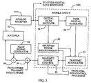
- an antenna 52 is provided at the cell-site for receiving multiple portable unit transmitted signals which are then provided to analog receiver 54 for amplification, frequency downconversion and IF processing.
- the analog signals output from receiver 54 are provided to a plurality of receiver modules for extraction of user directed information signals, generation of power adjustment commands, and modulation of user input information signals for transmission.
- Module 50N comprises digital data receiver 56, user digital baseband circuit 58, received power measurement circuitry 60, and transmit modulator 62.
- Digital data receiver 56 receives the wideband spread spectrum signals for correlating and despreading the portable unit N transmitted signal to a narrow band signal for transfer to an intended recipient communicating with portable unit N.
- Digital data receiver 56 provides the narrow band digital signals to user digital baseband circuitry 58.
- Digital data receiver 56 also provides the narrow band digital signal to received power measurement circuitry 60.
- Received power measurement circuitry 60 measures the power level in the received signal from portable unit N. Received power measurement circuitry 60 in response to the measured level of power generates either a "power-up” or “power-down” power adjustment command which is input to transmit modulator 62 for transmission to portable unit N.
- the appropriate power-up command data bits are generated, thus indicating that an increase in portable unit transmitter power is necessary.
- a power-down command is generated such that the portable unit transmitter power is reduced.
- the power adjustment command is utilized to maintain a nominal received power level at the cell-site exemplified by curve 40 ( Figure 2A).
- the signal output from digital data receiver 56 is provided to user digital baseband circuitry 58 where it is interfaced for coupling to the intended recipient via the system controller and switch.
- baseband circuitry 58 receives user information signals intended for portable unit N and provides them to transmit modulator 62.
- Transmit modulator 62 spread spectrum modulates the user addressable information signals for transmission to portable unit N. Transmit modulator 62 also receives the power adjustment command data bits from received power measurement circuitry 60. The power adjustment command data bits are also spread spectrum modulated by transmit modulator 62 for transmission to portable unit N. Transmit modulator 62 provides the spread spectrum modulated signal to summer 64 where it is combined with spread spectrum signals from other module transmit modulators also located at the cell-site.
- the combined spread spectrum signals are input to summer 66 where they are combined with a pilot signal provided by pilot signal generator 68. These combined signals are then provided to circuitry (not shown) for frequency upconversion from the IF frequency band to the RF frequency band and amplified. The RF signals are then provided to antenna 52 for transmission.
- forward link transmit power control circuitry may be disposed between summer 66 and antenna 52. This circuitry, under control of the cell-site processor, is responsive to power adjustment command signals transmitted by the portable unit which are demodulated at the cell-site receiver and provided to the cell-site control processor for coupling to the circuitry.
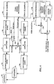
- the portable unit such as portable unit N, includes an antenna 70 for collecting cell-site transmitted signals and radiating portable unit generated CDMA signals.
- Portable unit N receives the pilot signal, setup channel signals and the portable unit N addressed signals using antenna 70, with duplexer 74 serving to route the received RF signals to frequency downconverter 90.
- Downconverter 90 operates to convert the received RF signals to an IF frequency.
- the IF frequency signals are coupled to a bandpass filter (not shown), where out of band frequency components are removed from the signals.
- the filtered signals are provided to variable gain IF amplifier 94, where the signals are amplified.
- the amplified signals are output from amplifier 94 to an IF to baseband (IF/BB) downconverter 96 for conversion to baseband, as well as for analog to digital (A/D) conversion.
- IF/BB IF to baseband
- A/D analog to digital
- the resultant digital samples of the in-phase (I) and quadrature phase (Q) CDMA signal components are provided to CDMA signal processor 98 for digital signal processing operations on the CDMA I/Q samples.
- the IF/BB downconverter 96 is also operative to generate a Received Signal Strength Indicator (RSSI) signal which is coupled to one input of comparator 100.
- RSSI Received Signal Strength Indicator
- the other input of comparator 100 is provided with an RSSI reference signal (RSSI REF) from the portable unit CDMA signal processor 98.
- RSSI REF RSSI reference signal
- the RSSI REF signal is indicative of a desired input power level to the CDMA signal processor 98.
- the RSSI and RSSI REF signals provided to comparator 100 are compared thereby, with the resulting receiver gain control signal (RX Gain) being coupled to the IF amplifier 94 and to a summer 102.
- This RX Gain signal is therefore indicative of the power received by the portable unit from the cell-site. Because signal power received at the portable unit will generally be proportional to its proximity to the cell-site, the distance of the portable unit from the cell-site may be inferred from the RX Gain signal. Accordingly, the RX Gain signal may be utilized in appropriately setting the gain of amplifier 104.
- Summer 102 is also provided with the TX GAIN ADJ signal generated by CDMA signal processor 98 in response to the power adjustment command signals transmitted from the cell-site, with the resultant transmitter gain (TX Gain) signal being coupled to the gain control input of IF transmit amplifier 104.
- the TX Gain signal is used to control the gain of the amplifier 104 so as to maintain the proper power level at the output of amplifier 104 to an IF/RF Upconverter 106.
- the CDMA signal processor 98 starts with the level of TX GAIN ADJ set to a nominal value. Each power-up command increases the value of TX GAIN ADJ, which corresponds to a resultant approximate 1 dB increase in amplifier gain. Each power-down command decreases the value of TX GAIN ADJ, corresponding to a resultant approximate 1 dB decrease in amplifier gain.
- the TX GAIN ADJ signal is converted to analog form before being supplied to summer 102 for combination with the RX Gain signal.
- the output of amplifier 104 is provided as an input to IF/RF Upconverter 106, while the input of amplifier 104 is supplied with the IF produced by the baseband to intermediate frequency (BB/IF) Upconverter 114.
- the BB/IF Upconverter 114 operates to translate the reverse link baseband CDMA I/Q samples generated by the CDMA signal processor 98 to an intermediate frequency.
- Amplifier 104 is a variable gain IF amplifier with the gain determined according to the TX Gain signal.
- the RF signal output from Upconverter 106 is then routed through duplexer 74 to the antenna 70 for transmission.
- a speech codec 120 coupled to the CDMA signal processor 98 produces an output speech signal S in response to speech information received by the portable unit from the cell-site.
- the CDMA I/Q Samples corresponding to the received speech information are processed by the CDMA signal processor 98, with the resulting speech parameters being provided to the speech codec 120 in digital form.
- a link quality signal (LQ) in the form of a scaled level of background interference is combined with the output speech signal S in an adder 124.
- the adder 124 is connected to a speaker (not shown) operative to produce an output signal audible to the user of the portable unit.
- the level of audible interference i.e., the noise level, present in the signal provided to the user is determined on the basis of the magnitude of the link quality signal LQ.
- the TX GAIN ADJ signal is provided to a microprocessor 130 disposed to generate a noise indicator gain signal G.
- the noise indicator gain signal is provided to one input of a multiplier 134, while the other input of multiplier 134 is supplied with a pseudorandom sequence from a random number generator 138.
- the output of random number generator 138 can be characterized as noise and random number generator 138 can be considered a noise generator.
- the link quality, signal LQ is thus seen to correspond to the resulting scaled pseudorandom sequence produced by the multiplier 134.
- the microprocessor 130 will generally include a look-up table of noise indicator gain signals indexed as a function of TX GAIN ADJ.
- the noise indicator gain signals are monotonically related in magnitude to the value of TX GAIN ADJ for those values of TX GAIN ADJ exceeding a minimum threshold TX min ( Figure 2B). It is anticipated that for values of TX GAIN ADJ less than TX min , the magnitudes of the corresponding noise indicator gain signals will be set to zero. In this way, background interference noise is prevented from being injected into the portable unit audible signal in response to minor deviations in the propagation characteristics of the reverse and forward transmission paths.
- the magnitude of the noise indicator signals will preferably be proportional to corresponding values of TX GAIN ADJ.
- the random number generator 138 produces a pseudorandom number sequence of predetermined length relative to each voice frame.
- a pseudorandom sequence having a length of approximately 160 samples is utilized, assuming a voice frame of length 20 msec. and a sampling rate of 8 kHz.
- An alternative embodiment of the link quality improvement technique of the invention may be implemented in existing cellular systems without modification of the system portable units. This is accomplished by synthesizing within the cell-site, rather than within the portable units, the link quality signals associated with each portable unit. More specifically, the value of TX GAIN ADJ for the portable unit may be generated within the cell-site itself based on the power adjustment commands sent to the portable unit. Alternatively, each portable unit periodically transmits the cell-site the value of the particular TX GAIN ADJ signal generated therein. In either case, within the cell-site the value of the TX GAIN ADJ signal for a given portable unit is accumulated.
- the cell-site includes a random number generator 200 for providing a pseudorandom sequence to a multiplier 210.
- the output of random number generator 200 can be a digital noise signal and random number generator 200 may be noise generator.
- the pseudorandom sequence is scaled at multiplier 210 by a noise indicator gain signal G1 provided by a cell-site microprocessor 220.
- the cell-site microprocessor 220 will generally include a look-up table substantially identical to the look-up table included within microprocessor 130 (i.e., one in which noise indicator gain signals are indexed as a function of the TX GAIN ADJ signal).
- the link quality signal LQ'(n) is combined in digital adder 240 with the sequence of speech samples and the resultant s(n) is input to a cell-site speech codec 230.
- the associated voice channel operate at a variable data rate.
- the intent in using a variable data rate is to lower the data rate when there is no voice activity, thereby reducing interference generated by the particular voice channel to other users.
- 07/713,661 filed June 11, 1991 (published as WO-A-92 22 891) discloses a speech codec for processing data at four different data rates based on voice activity on a 20 msec frame basis.
- the received speech parameters may specifv data rates of 9.6 kbps, 4.8 kbps, 2.4 kbps or 1.2 kbps.
- the link quality signal LQ'(n) should not be sufficient to increase the nominal data rate above the rate that the speech information would require.
- the composite sequence s(n) output from digital adder 240 is provided to cell-site speech codec 230.
- Cell-site speech codec 230 vocodes s(n) to produce output data S(n).
- the sequence S(n) is convolutional encoded, with repetition, and interleaved by encoder/interleaver 260 in order to provide error detection and correction functions which allow the system to operate at a much lower signal-to-noise and interference ratio.
- Techniques for convolutional encoding, repetition, and interleaving are well known in the art.
- the resulting encoded speech parameters P(n) are generally summed with the pilot and setup carriers and with the other voice carriers and modulated onto an RF carrier.
- the method of creating the noise may take on a variety of forms.
- One method which might prove the most efficient is to modify speech codec parameters to increase the background noise in response to the TX GAIN ADJ signal.
- the present invention seeks to alert the user of a diminishing signal level by adding white noise to the audible signal heard by the user.
- Many other alternative ways of alerting the user are envisioned such as a periodic tone which varies in frequency with TX GAIN ADJ or a continuous tone that increases in volume with TX GAIN ADJ.
- a less intrusive manner of implementing the present invention is to provide a visual display which indicates that relative level of TX GAIN ADJ.
Landscapes
- Engineering & Computer Science (AREA)
- Computer Networks & Wireless Communication (AREA)
- Signal Processing (AREA)
- Physics & Mathematics (AREA)
- Probability & Statistics with Applications (AREA)
- Mobile Radio Communication Systems (AREA)
- Maintenance And Management Of Digital Transmission (AREA)
- Two-Way Televisions, Distribution Of Moving Picture Or The Like (AREA)
- Communication Control (AREA)
- Cable Transmission Systems, Equalization Of Radio And Reduction Of Echo (AREA)
- Transmitters (AREA)
Claims (34)
- Système d'amélioration de la qualité d'un signal destiné à être utilisé dans un système de communication dans lequel des utilisateurs du système se communiquent des signaux d'informations par l'intermédiaire d'au moins un site de cellules (12) en utilisant des signaux de communication, pour améliorer la qualité des signaux (20b) émis vers ledit au moins un site de cellules (12) à partir d'un module de communication portable (16) utilisé par l'un des utilisateurs du système, le site de cellules (12) et le module de communication portable (16) comprenant chacun un émetteur (64, 68, 66, 52 ; 106, 74, 70) et un récepteur (52, 54, 56 ; 70, 74, 90, 94, 96), le récepteur (70, 74, 90, 94, 96) du module de communication portable (16) agissant pour fournir un signal de sortie (S) audit utilisateur du système, le système comprenant :caractérisé en ce que le système comprend :un premier moyen de mesure de puissance (60), couplé au récepteur de site de cellules (52, 54, 56) pour mesurer la puissance de signal dans chaque signal de communication (20b) dirigé vers le site de cellules (12) à partir de l'émetteur (106, 74, 70) du module de communication portable (16) ;un premier moyen de générateur de commandes de réglage de puissance (62, 63), couplé à l'émetteur de site de cellules (64, 68, 66) et au premier moyen de mesure de puissance (60) pour produire un premier ensemble de commandes de réglage de puissance correspondant aux variations de mesures de puissance du premier moyen de mesure de puissance (60) par rapport à un premier niveau de puissance prédéterminé, l'émetteur de site de cellules (64, 68, 66) émettant le premier ensemble de commandes de réglage de puissance ;un moyen (130, 138, 134 ou 220, 200, 210) pour produire un signal de qualité de liaison (LQ ou LQ'(n)) indicatif de la puissance du signal émis reçue au niveau du site de cellules (12) au moins partiellement en réponse au premier ensemble de commandes de réglage de puissance quand le module portable (16) agit à sa limite de puissance d'émission maximum ou près de celle-ci etun moyen de sommation (124 ou 240) pour combiner le signal de qualité de liaison (LQ ; LQ'(n)) et le signal de sortie (S) fourni audit utilisateur du système ;d'où il résulte que, en réponse au signal de qualité de liaison (LQ ou LQ'(n)), ledit utilisateur du système peut régler la position du module de communication portable (16) pour améliorer la qualité des signaux (20b) transmis au site de cellules (12).
- Système d'amélioration de la qualité d'un signal selon la revendication 1, caractérisé en ce que le moyen (130, 138, 134) pour produire le signal de qualité de liaison (LQ) est disposé dans le module de communication portable (16) et en ce que le signal de qualité de liaison (LQ) est indicatif du niveau de puissance du signal (20b) reçue au niveau du site de cellules (12) par rapport à un niveau optimum prédéterminé, le moyen (130, 138, 134) pour produire un signal de qualité de liaison (LQ) étant connecté au moyen de sommation (124).
- Système d'amélioration de la qualité d'un signal selon la revendication 2, caractérisé en ce qu'il comprend en outre un moyen amplificateur (104) couplé à l'émetteur (106, 74, 70) et au récepteur (70, 74, 90, 94, 96) du module de communication portable (16), le moyen amplificateur (104) agissant en réponse au premier ensemble de commandes de réglage de puissance dirigées vers le module de communication portable (16) pour régler la puissance du signal d'émission du module de communication portable (16).
- Système d'amélioration de la qualité d'un signal selon la revendication 1, caractérisé en ce qu'il comprend en outre un moyen codeur-décodeur de parole (120) pour générer le signal de sortie (S) sous forme d'un signal audible et en ce que le moyen (130, 138, 134 ; 220, 200, 210) pour produire le signal de qualité de liaison (LQ) comprend un moyen (130, 138, 134 ; 220, 200, 210) pour produire un signal de qualité de liaison audible.
- Système d'amélioration de la qualité d'un signal selon la revendication 1, caractérisé en ce que le moyen (220, 200, 210) pour produire le signal de qualité de liaison (LQ'(n)) est disposé dans le site de cellules (12), l'émetteur du site de cellules (106, 74, 70) comprenant un moyen pour émettre le signal de qualité de liaison (LQ'(n)) vers le module de communication portable (16).
- Système d'amélioration de la qualité d'un signal selon la revendication 4 ou 5, caractérisé en ce que le moyen (130, 138, 134 ; 220, 200, 210) pour produire le signal de qualité de liaison (LQ ; LQ'(n)) comprend un moyen générateur de bruit (138 ; 200) pour produire un signal de bruit de fond et comprend en outre un moyen (130, 134 ; 220, 210) pour normaliser le signal de bruit de fond en fonction du premier ensemble de commandes de réglage de puissance.
- Système d'amélioration de la qualité d'un signal selon la revendication 6, caractérisé en ce que le moyen (130, 134 ; 220, 210) de normalisation comprend :un moyen de microprocesseur (130 ; 220) pour accumuler le premier ensemble de commandes de réglage de puissance et pour produire en réponse un signal de gain indicateur de bruit (G ; G1) ; etun moyen (134 ; 210) pour multiplier le signal de bruit de fond par le signal de gain indicateur de bruit (G ; G1).
- Système d'amélioration de la qualité d'un signal selon la revendication 7 prise dans sa dépendance de la revendication 4, caractérisé en ce que le moyen de microprocesseur (130 ; 220) comprend un moyen pour déterminer la valeur moyenne du premier ensemble de commandes de réglage de puissance et comprend en outre un moyen pour régler l'amplitude du signal de gain indicateur de bruit (G ; G1) en fonction de la valeur moyenne, dans lequel l'amplitude est une fonction de la valeur moyenne.
- Système d'amélioration de la qualité d'un signal selon la revendication 1, comprenant en outre un moyen de processeur de signal (98), disposé dans le module de communication portable (16), pour :accumuler le premier ensemble de commandes de réglage de puissance en un ensemble accumulé de commandes de réglage de puissance ;déterminer une valeur moyenne correspondant à l'ensemble accumulé ; etcomparer la valeur moyenne à un réglage de niveau de commande de gain prédéterminé et, sur la base de cette comparaison, produire un signal de réglage de gain d'émetteur (TX GAIN ADJUST).
- Système d'amélioration de la qualité d'un signal selon la revendication 9, caractérisé en ce qu'il comprend en outre :un moyen de microprocesseur (130) pour produire le signal de qualité de liaison (LQ) en réponse au signal de réglage de gain d'émetteur (TX GAIN ADJ) ; etun moyen amplificateur (104) couplé opérativement à l'émetteur (106, 74, 70) du module de communication portable (16) pour recevoir le signal de réglage de gain d'émetteur (TX GAIN ADJ), le moyen amplificateur (104) comprenant un moyen pour faire varier la puissance de l'émetteur (106, 74, 70) en accord avec le signal de réglage de gain d'émetteur (TX GAIN ADJ).
- Système d'amélioration de la qualité d'un signal selon l'une quelconque des revendications précédentes, dans lequel les signaux utilisés sont des signaux à étalement de spectre à accès multiple par différence de code (CDMA).
- Module de communication portable (16) qui communique dans un environnement de communication sans fil et peut indiquer une qualité de liaison de communication, le module de communication (16) comprenant :caractérisé en ce que le module de communication (16) comprend :une partie réceptrice (70, 74, 90, 94, 96) qui reçoit les signaux en provenance de l'environnement de communication sans fil ;un premier processeur (98) couplé à la partie réceptrice (70, 74, 90, 94, 96) et adapté à agir en réponse à une commande de réglage de puissance émise à partir d'un site de cellules (12) indicatrice de la puissance du signal émis (20b) reçue au niveau du site de cellules (12), pour produire un signal de réglage de gain d'émetteur (TX GAIN ADJ) pour régler le gain de l'émetteur (106, 74, 70) du module de communication portable (16) ;un second processeur (130) couplé au premier processeur (98) pour produire un signal de gain indicateur de bruit (G) en réponse au signal de réglage de gain d'émetteur (TX GAIN ADJ) ;un générateur de nombres aléatoires (138) pour produire une séquence de nombres ; etun multiplieur (134) couplé au second processeur (130) et au générateur de nombres aléatoires (138) pour produire un signal de qualité de liaison (LQ) indicatif de la puissance du signal émis reçue au niveau du site de cellules (12) en réponse au signal de gain indicateur de bruit (G) et de la séquence de nombres quand le module portable (16) agit à sa limite de puissance d'émission maximum ou près de cette limite, d'où il résulte que, en réponse au signal de qualité de liaison (LQ), un utilisateur du système peut régler la position du module de communication portable (16) pour améliorer la qualité des signaux (20b) émis vers le site de cellules (12).
- Module de communication (16) selon la revendication 12, caractérisé en ce qu'il comprend en outre :un codeur-décodeur de parole (120) couplé au premier processeur (98) pour produire un signal de parole (S) ;un sommateur (124) couplé au codeur-décodeur de parole (120) et au multiplieur (134) pour produire un signal de sortie audible à partir du signal de parole (S) et du signal de qualité de liaison (LQ) ; etun transducteur audio couplé au sommateur (124) pour émettre le signal de sortie audible.
- Module de communication (16) selon la revendication 12, caractérisé en ce que la séquence de nombres est une séquence de nombres pseudo-aléatoire.
- Procédé d'amélioration de la qualité d'un signal destiné à être utilisé dans un système de communication dans lequel des utilisateurs du système se communiquent des signaux d'informations par l'intermédiaire d'au moins un site de cellules (12) en utilisant des signaux de communication, pour améliorer la qualité des signaux (20b) émis vers ledit au moins un site de cellules (12) à partir d'un module de communication portable (16) utilisé par l'un des utilisateurs du système, le site de cellules (12) et le module de communication portable (16) comprenant chacun un émetteur (64, 68, 66, 52 ; 106, 74, 70) et un récepteur (52, 54, 56 ; 70, 74, 90, 94, 96), le récepteur (70, 74, 90, 94, 96) du module de communication portable (16) agissant pour fournir un signal de sortie (S) audit utilisateur du système, le procédé comprenant les étapes suivantes :caractérisé par les étapes supplémentaires suivantes :mesurer la puissance de signal dans chaque signal de communication (20b) dirigé vers le site de cellules (12) à partir de l'émetteur (106, 74, 70) du module de communication portable (16) ;produire un ensemble de commandes de réglage de puissance correspondant aux variations de puissance du signal mesuré par rapport à un premier niveau de puissance prédéterminé, et émettre ledit ensemble de commandes de réglage de puissance à partir du site de cellules (12) vers le module de communication portable (16) ;produire un signal de qualité de liaison (LQ ou LQ'(n)) indicatif de la puissance du signal émis reçue au niveau du site de cellules (12) au moins partiellement en réponse au premier ensemble de commandes de réglage de puissance quand le module portable (16) agit à sa limite de puissance d'émission maximum ou près de celle-ci ; etcombiner le signal de qualité de liaison (LQ ; LQ'(n)) et le signal de sortie (S) fourni audit utilisateur du système ;d'où il résulte que, en réponse au signal de qualité de liaison (LQ ou LQ'(n)), ledit utilisateur du système peut régler la position du module de communication portable (16) pour améliorer la qualité des signaux (20b) transmis au site de cellules (12).
- Procédé selon la revendication 15, d'amélioration de la qualité d'un signal dans un système de communication comprenant un site de cellules (12) et un ensemble de modules portables dans lequel au moins l'un de l'ensemble de modules de communication portables (16) a plusieurs positions par rapport au site de cellules (12), le procédé comprenant les étapes suivantes :mesurer le niveau de puissance du signal (20b) reçu à partir d'un module portable (16) particulier de l'ensemble de modules de communication portables (16) ;comparer le niveau de puissance mesuré à un niveau de puissance désiré et produire une commande de réglage de puissance sur la base de la différence entre le niveau de puissance mesuré et le niveau de puissance désiré ;fournir au module portable (16) particulier la commande de réglage de puissance ;accumuler au niveau du module portable (16) particulier un ensemble de commandes de réglage de puissance et produire une valeur moyenne ; etproduire au niveau du module portable (16) particulier le signal de qualité de liaison (LQ) quand la valeur moyenne dépasse un seuil prédéterminé ;dans lequel la position du module de communication portable particulier (16) est réglée par rapport au site de cellules (12) en réponse au signal de qualité de liaison (LQ).
- Procédé selon la revendication 16, caractérisé en ce que le signal de qualité de liaison (LQ) est un signal de bruit audible.
- Procédé selon la revendication 17, caractérisé en ce que le signal de bruit audible augmente en volume quand le signal de qualité de liaison (LQ) dépasse encore le seuil prédéterminé.
- Procédé selon la revendication 16, caractérisé en ce que le signal de qualité de liaison (LQ) est présenté sur un affichage visible.
- Procédé selon la revendication 16, caractérisé en ce que le signal de qualité de liaison (LQ) est une tonalité audible.
- Procédé selon la revendication 20, dans lequel la tonalité audible est périodique.
- Procédé selon la revendication 21, caractérisé en ce que la période de la tonalité audible périodique augmente en fonction de la quantité dont la valeur moyenne dépasse le seuil prédéterminé.
- Procédé selon la revendication 16, caractérisé en ce que la valeur moyenne commande le niveau de puissance du signal (20b) reçu à partir du module de communication portable (16) particulier au niveau du site de cellules (12).
- Procédé selon la revendication 15, destiné à être utilisé par le système de communication utilisant des signaux de communication à étalement de spectre à accès multiple par différence de code (CDMA), le site de cellules (12) et le module de communication portable (16) comprenant chacun un émetteur (64, 68, 66, 52 ; 106, 74, 70) et un récepteur (52, 54, 56 ; 70, 74, 90, 94, 96), dans lequel le récepteur (70, 74, 90, 94, 96) du module de communication portable (16) agit pour fournir un signal de sortie audit utilisateur du système, ce procédé comprenant les étapes suivantes :mesurer la puissance de signal de chaque signal de communication CDMA (20b) dirigé vers le site de cellules (12) à partir de l'émetteur (106, 74, 70) du module de communication portable (16) ;produire l'ensemble de commandes de réglage de puissance correspondant aux variations de mesures de la puissance de signal (20b) dirigée vers le site de cellules (12) par rapport à un premier niveau de puissance prédéterminé, l'émetteur du site de cellules (64, 68, 66, 52) émettant le premier ensemble de commandes de réglage de puissance ;produire le signal de qualité de liaison (LQ ; LQ'(n)) au moins partiellement en réponse à l'ensemble de commandes de réglage de puissance ; etcombiner le signal de qualité de liaison (LQ ; LQ'(n)) au signal de sortie (S) fourni audit utilisateur du système ;d'où il résulte que, en réponse au signal de qualité de liaison (LQ ; LQ'(n)), ledit utilisateur du système peut régler la position du module de communication portable (16) pour améliorer la qualité des signaux (20b) émis vers le site de cellules (12).
- Procédé selon la revendication 24, caractérisé en ce qu'il comprend en outre l'étape consistant à produire le signal de sortie (S) sous forme d'un signal audible, l'étape de génération du signal de qualité de liaison (LQ) comprenant l'étape de production d'un signal de qualité de liaison audible.
- Procédé selon la revendication 25, caractérisé en ce que l'étape de génération du signal de qualité de liaison (LQ) comprend l'étape consistant à produire un signal de bruit de fond et comprend en outre l'étape consistant à normaliser le signal de bruit de fond en accord avec le premier ensemble de commandes de réglage de puissance.
- Procédé selon la revendication 26, caractérisé en ce que l'étape de normalisation comprend les étapes suivantes :accumuler le premier ensemble de commandes de réglage de puissance et produire en réponse un signal de gain indicateur de bruit (G) ;multiplier le signal de bruit de fond par le signal de gain indicateur de bruit (G).
- Procédé selon la revendication 27, caractérisé en ce qu'il comprend en outre les étapes suivantes :déterminer une valeur moyenne du premier ensemble de commandes de réglage de puissance ; etrégler l'amplitude du signal de gain indicateur de bruit (G) en accord avec la valeur moyenne, l'amplitude étant inversement associée à la valeur moyenne.
- Procédé selon la revendication 24, caractérisé en ce qu'il comprend en outre l'étape consistant à émettre le signal de qualité de liaison (LQ'(n)) vers le module de communication portable (16).
- Procédé selon la revendication 24, caractérisé en ce qu'il comprend en outre les étapes suivantes :accumuler le premier ensemble de commandes de réglage de puissance en une valeur moyenne ;comparer la valeur moyenne à un réglage de niveau de commande de gain prédéterminé ; etsur la base de la comparaison, produire un premier signal de réglage de gain d'émetteur (TX GAIN ADJ).
- Procédé selon la revendication 30, caractérisé en ce qu'il comprend les étapes suivantes :compiler une table dans laquelle des valeurs du signal de qualité de liaison (LQ ; LQ'(n)) sont indexées en fonction des valeurs correspondantes du signal de réglage de gain d'émetteur (TX GAIN ADJ), etdéterminer la valeur du signal de qualité de liaison (LQ, LQ'n)) à partir de la table en utilisant le premier signal de réglage de gain d'émetteur (TX GAIN ADJ) en tant qu'indice dans la table.
- Procédé selon la revendication 24, caractérisé en ce qu'il comprend en outre l'étape consistant à régler la puissance du signal d'émission du module de communication portable (16) en réponse au premier ensemble de commandes de réglage de puissance.
- Procédé selon la revendication 15, pour améliorer les communications avec une radio portable (16) qui communique dans un environnement de communication sans fil, ce procédé comprenant les étapes suivantes :recevoir des signaux à partir de l'environnement de communication sans fil ;produire un signal de réglage de gain d'émetteur (TX GAIN ADJ) en réponse aux signaux reçus ;fournir le signal de qualité de liaison (LQ) dans la radio portable (16) en :produisant un signal de gain indicateur de bruit (G) en réponse au signal de réglage de gain d'émetteur ;produisant une séquence de nombres ; etsommant le signal de gain indicateur de bruit (G) et la séquence de nombres pour produire le signal de qualité de liaison (LQ).
- Procédé selon la revendication 33, caractérisé en ce qu'il comprend en outre les étapes suivantes :produire un signal de parole à partir d'un codeur-décodeur de parole (120) ;sommer le signal de parole (S) et le signal de qualité de liaison (LQ) pour produire un signal de sortie audible ; etémettre le signal de sortie audible par l'intermédiaire d'un transducteur audio.
Priority Applications (1)
| Application Number | Priority Date | Filing Date | Title |
|---|---|---|---|
| SI9530269T SI0692162T1 (en) | 1994-02-01 | 1995-02-01 | Method and apparatus for providing a communication link quality indication |
Applications Claiming Priority (3)
| Application Number | Priority Date | Filing Date | Title |
|---|---|---|---|
| US08/190,517 US5469471A (en) | 1994-02-01 | 1994-02-01 | Method and apparatus for providing a communication link quality indication |
| PCT/US1995/001339 WO1995021494A1 (fr) | 1994-02-01 | 1995-02-01 | Procede et appareil fournissant une indication de la qualite d'une liaison de communication |
| US190517 | 1998-11-12 |
Publications (2)
| Publication Number | Publication Date |
|---|---|
| EP0692162A1 EP0692162A1 (fr) | 1996-01-17 |
| EP0692162B1 true EP0692162B1 (fr) | 1999-03-31 |
Family
ID=22701673
Family Applications (1)
| Application Number | Title | Priority Date | Filing Date |
|---|---|---|---|
| EP95910159A Expired - Lifetime EP0692162B1 (fr) | 1994-02-01 | 1995-02-01 | Procede et appareil fournissant une indication de la qualite d'une liaison de communication |
Country Status (21)
| Country | Link |
|---|---|
| US (1) | US5469471A (fr) |
| EP (1) | EP0692162B1 (fr) |
| JP (1) | JP3014765B2 (fr) |
| KR (1) | KR100233782B1 (fr) |
| CN (1) | CN1123073A (fr) |
| AT (1) | ATE178444T1 (fr) |
| AU (1) | AU681771B2 (fr) |
| BR (1) | BR9505642A (fr) |
| CA (1) | CA2158157C (fr) |
| DE (1) | DE69508664T2 (fr) |
| DK (1) | DK0692162T3 (fr) |
| ES (1) | ES2129810T3 (fr) |
| FI (1) | FI954617A7 (fr) |
| GR (1) | GR3030151T3 (fr) |
| IL (1) | IL112487A (fr) |
| MX (1) | MX9504148A (fr) |
| MY (1) | MY130543A (fr) |
| RU (1) | RU2127948C1 (fr) |
| TW (1) | TW306101B (fr) |
| WO (1) | WO1995021494A1 (fr) |
| ZA (1) | ZA95600B (fr) |
Families Citing this family (119)
| Publication number | Priority date | Publication date | Assignee | Title |
|---|---|---|---|---|
| US5603113A (en) * | 1993-06-16 | 1997-02-11 | Oki Telecom | Automatic gain control circuit for both receiver and transmitter adjustable amplifiers including a linear signal level detector with DC blocking, DC adding, and AC removing components |
| US5722068A (en) * | 1994-01-26 | 1998-02-24 | Oki Telecom, Inc. | Imminent change warning |
| JP2993554B2 (ja) * | 1994-05-12 | 1999-12-20 | エヌ・ティ・ティ移動通信網株式会社 | 送信電力制御法および前記送信電力制御法を用いた通信装置 |
| US5610906A (en) * | 1994-06-29 | 1997-03-11 | Interdigital Technology Corporation | Spread-spectrum changeable base station |
| US5697053A (en) * | 1994-07-28 | 1997-12-09 | Lucent Technologies Inc. | Method of power control and cell site selection |
| US5604806A (en) * | 1995-01-20 | 1997-02-18 | Ericsson Inc. | Apparatus and method for secure radio communication |
| ZA965340B (en) | 1995-06-30 | 1997-01-27 | Interdigital Tech Corp | Code division multiple access (cdma) communication system |
| DE19605418B4 (de) * | 1996-02-14 | 2014-11-20 | Ipcom Gmbh & Co. Kg | Verfahren zur Aufbereitung von Daten, insbesondere für die Übertragung mit veränderlicher Kanalbitrate |
| JP2000506699A (ja) * | 1996-03-12 | 2000-05-30 | エリクソン インコーポレイテッド | 注入された音声信号を使用した移動無線電話のアンテナ再位置合せのための方法及び装置 |
| US6678311B2 (en) | 1996-05-28 | 2004-01-13 | Qualcomm Incorporated | High data CDMA wireless communication system using variable sized channel codes |
| FI103555B (fi) * | 1996-06-17 | 1999-07-15 | Nokia Mobile Phones Ltd | Lähetystehon säätö langattomassa pakettidatasiirrossa |
| US5857155A (en) * | 1996-07-10 | 1999-01-05 | Motorola, Inc. | Method and apparatus for geographic based control in a communication system |
| US5933781A (en) * | 1997-01-31 | 1999-08-03 | Qualcomm Incorporated | Pilot based, reversed channel power control |
| WO1998043453A1 (fr) * | 1997-03-26 | 1998-10-01 | Motorola Inc. | Procede et appareil destines a fixer un niveau de puissance emettrice d'arrivee |
| ATE452477T1 (de) * | 1997-05-14 | 2010-01-15 | Qualcomm Inc | Eine teilnehmereinheit und verfahren zur nutzung in einem drahtlosen kommunikationssystem |
| US6347217B1 (en) * | 1997-05-22 | 2002-02-12 | Telefonaktiebolaget Lm Ericsson (Publ) | Link quality reporting using frame erasure rates |
| US5982760A (en) * | 1997-06-20 | 1999-11-09 | Qualcomm Inc. | Method and apparatus for power adaptation control in closed-loop communications |
| US6101179A (en) * | 1997-09-19 | 2000-08-08 | Qualcomm Incorporated | Accurate open loop power control in a code division multiple access communication system |
| US6128506A (en) * | 1997-09-24 | 2000-10-03 | Telefonaktiebolaget Lm Ericsson | Integrated power control and congestion control in a communication system |
| US7184426B2 (en) | 2002-12-12 | 2007-02-27 | Qualcomm, Incorporated | Method and apparatus for burst pilot for a time division multiplex system |
| US9118387B2 (en) | 1997-11-03 | 2015-08-25 | Qualcomm Incorporated | Pilot reference transmission for a wireless communication system |
| US6205131B1 (en) * | 1997-12-16 | 2001-03-20 | Sony Corporation | Broadband implementation of supplemental code channel carrier phase offsets |
| EP1758266A3 (fr) * | 1998-03-03 | 2014-04-23 | NEC Corporation | Procédé de contrôle de la puissance de transmission dans un système de communication mobile de type cellulaire |
| US6658050B1 (en) * | 1998-09-11 | 2003-12-02 | Ericsson Inc. | Channel estimates in a CDMA system using power control bits |
| US7047185B1 (en) * | 1998-09-15 | 2006-05-16 | Skyworks Solutions, Inc. | Method and apparatus for dynamically switching between speech coders of a mobile unit as a function of received signal quality |
| US7346120B2 (en) | 1998-12-11 | 2008-03-18 | Freescale Semiconductor Inc. | Method and system for performing distance measuring and direction finding using ultrawide bandwidth transmissions |
| US7110473B2 (en) * | 1998-12-11 | 2006-09-19 | Freescale Semiconductor, Inc. | Mode controller for signal acquisition and tracking in an ultra wideband communication system |
| KR100551153B1 (ko) * | 1999-02-11 | 2006-02-13 | 유티스타콤코리아 유한회사 | Cdma 시스템에서의 단말기/기지국간 역방향 성능 자동측정 장치 및 방법 |
| US6370109B1 (en) * | 1999-03-10 | 2002-04-09 | Qualcomm Incorporated | CDMA signal power control using quadrature signal calculations |
| DE60040137D1 (de) | 1999-03-12 | 2008-10-16 | Qualcomm Inc | Verfahren und vorrichtung zur leistungszuteilung auf eine rückwärtsleistungssteuerung eines kommunikationssystems |
| DE50007132D1 (de) | 1999-03-25 | 2004-08-26 | Siemens Ag | Verfahren zur regelung der sendeleistung in einem mobilfunksystem und entsprechendes mobilfunksystem |
| KR100615419B1 (ko) * | 1999-08-17 | 2006-08-25 | 에스케이 텔레콤주식회사 | 역방향 성능 향상을 위한 무선통신 시스템 |
| US8064409B1 (en) | 1999-08-25 | 2011-11-22 | Qualcomm Incorporated | Method and apparatus using a multi-carrier forward link in a wireless communication system |
| US6865164B1 (en) | 1999-09-08 | 2005-03-08 | Motorola, Inc. | Packet transmission method |
| WO2001018996A1 (fr) * | 1999-09-08 | 2001-03-15 | Motorola Inc. | Procede de transmission par paquets |
| US6621804B1 (en) | 1999-10-07 | 2003-09-16 | Qualcomm Incorporated | Method and apparatus for predicting favored supplemental channel transmission slots using transmission power measurements of a fundamental channel |
| EP1111822A3 (fr) * | 1999-12-24 | 2003-10-22 | Lucent Technologies Inc. | Indicateur de qualité pour canal sans fils |
| US8099122B1 (en) * | 2000-06-05 | 2012-01-17 | Qualcomm Incorporated | Method and apparatus for improved forward link power control while in soft handoff |
| US7295509B2 (en) | 2000-09-13 | 2007-11-13 | Qualcomm, Incorporated | Signaling method in an OFDM multiple access system |
| US9130810B2 (en) | 2000-09-13 | 2015-09-08 | Qualcomm Incorporated | OFDM communications methods and apparatus |
| US7068683B1 (en) | 2000-10-25 | 2006-06-27 | Qualcomm, Incorporated | Method and apparatus for high rate packet data and low delay data transmissions |
| US6973098B1 (en) | 2000-10-25 | 2005-12-06 | Qualcomm, Incorporated | Method and apparatus for determining a data rate in a high rate packet data wireless communications system |
| US6542270B2 (en) * | 2000-12-08 | 2003-04-01 | Motorola, Inc. | Interference-robust coded-modulation scheme for optical communications and method for modulating illumination for optical communications |
| US7903610B2 (en) | 2001-04-03 | 2011-03-08 | Nokia Corporation | Reverse link handoff mechanism with hybrid ARQ and cell site selection |
| US7218904B2 (en) * | 2001-10-26 | 2007-05-15 | Texas Instruments Incorporated | Removing close-in interferers through a feedback loop |
| US7082107B1 (en) | 2001-11-26 | 2006-07-25 | Intel Corporation | Power control in wireless communications based on estimations of packet error rate |
| US6963755B2 (en) * | 2002-01-09 | 2005-11-08 | Qualcomm, Incorporated | Method and apparatus for coherently combining power control commands to initialize communication |
| RU2280328C2 (ru) * | 2002-02-09 | 2006-07-20 | Эл Джи Электроникс Инк. | Способ управления мощностью нисходящего коллективного канала для системы связи шмдкр |
| US7050759B2 (en) * | 2002-02-19 | 2006-05-23 | Qualcomm Incorporated | Channel quality feedback mechanism and method |
| TWI342686B (en) | 2002-12-04 | 2011-05-21 | Interdigital Tech Corp | Reliability detection of channel quality indicator (cqi) and application to outer loop power control |
| KR20040060274A (ko) | 2002-12-30 | 2004-07-06 | 엘지전자 주식회사 | 무선링크의 전력제어방법 |
| US7340269B2 (en) * | 2003-02-04 | 2008-03-04 | Lg Electronics Inc. | Uplink transmission power control method |
| US20040181611A1 (en) * | 2003-03-14 | 2004-09-16 | Viresh Ratnakar | Multimedia streaming system for wireless handheld devices |
| US7558818B2 (en) * | 2003-06-06 | 2009-07-07 | Meshnetworks, Inc. | System and method for characterizing the quality of a link in a wireless network |
| DE10329846B4 (de) | 2003-07-02 | 2009-01-15 | Disetronic Licensing Ag | System und Verfahren zur Kommunikationsüberwachung |
| GB0326365D0 (en) * | 2003-11-12 | 2003-12-17 | Koninkl Philips Electronics Nv | A radio communication system,a method of operating a communication system,and a mobile station |
| KR100946923B1 (ko) | 2004-03-12 | 2010-03-09 | 삼성전자주식회사 | 직교 주파수 분할 다중 방식을 사용하는 통신 시스템에서 채널 품질 정보의 송수신 장치 및 방법, 그리고 그에 따른 시스템 |
| US7200129B2 (en) * | 2004-03-12 | 2007-04-03 | Motorola, Inc. | Method of signaling reverse channel information with minimal voice/data delay |
| KR100724989B1 (ko) * | 2004-04-14 | 2007-06-04 | 삼성전자주식회사 | 직교 주파수 분할 다중 접속 방식을 사용하는 통신시스템에서 전력 제어 장치 및 방법 |
| EP1603262B1 (fr) * | 2004-05-28 | 2007-01-17 | Alcatel | Procédé d'adaptation d'un codec vocal à plusieurs débits |
| US7594151B2 (en) * | 2004-06-18 | 2009-09-22 | Qualcomm, Incorporated | Reverse link power control in an orthogonal system |
| US7197692B2 (en) * | 2004-06-18 | 2007-03-27 | Qualcomm Incorporated | Robust erasure detection and erasure-rate-based closed loop power control |
| US8452316B2 (en) | 2004-06-18 | 2013-05-28 | Qualcomm Incorporated | Power control for a wireless communication system utilizing orthogonal multiplexing |
| US9137822B2 (en) | 2004-07-21 | 2015-09-15 | Qualcomm Incorporated | Efficient signaling over access channel |
| US9148256B2 (en) | 2004-07-21 | 2015-09-29 | Qualcomm Incorporated | Performance based rank prediction for MIMO design |
| US20060068773A1 (en) * | 2004-09-28 | 2006-03-30 | Stambaugh Mark A | Method and system for concurrent testing of multiple cellular phones |
| US20060094485A1 (en) * | 2004-10-28 | 2006-05-04 | Interdigital Technology Corporation | Method and apparatus for preventing communication link degradation due to the detrimental orientation of a mobile station |
| US20060094449A1 (en) * | 2004-10-28 | 2006-05-04 | Interdigital Technology Corporation | Method and apparatus for preventing communication link degradation due to the disengagement or movement of a self-positioning transceiver |
| US7747271B2 (en) | 2005-03-02 | 2010-06-29 | Qualcomm Incorporated | Radiated power control for a multi-antenna transmission |
| US9246560B2 (en) | 2005-03-10 | 2016-01-26 | Qualcomm Incorporated | Systems and methods for beamforming and rate control in a multi-input multi-output communication systems |
| US9154211B2 (en) | 2005-03-11 | 2015-10-06 | Qualcomm Incorporated | Systems and methods for beamforming feedback in multi antenna communication systems |
| US8942639B2 (en) | 2005-03-15 | 2015-01-27 | Qualcomm Incorporated | Interference control in a wireless communication system |
| US8848574B2 (en) | 2005-03-15 | 2014-09-30 | Qualcomm Incorporated | Interference control in a wireless communication system |
| US9143305B2 (en) | 2005-03-17 | 2015-09-22 | Qualcomm Incorporated | Pilot signal transmission for an orthogonal frequency division wireless communication system |
| US9520972B2 (en) | 2005-03-17 | 2016-12-13 | Qualcomm Incorporated | Pilot signal transmission for an orthogonal frequency division wireless communication system |
| US9461859B2 (en) | 2005-03-17 | 2016-10-04 | Qualcomm Incorporated | Pilot signal transmission for an orthogonal frequency division wireless communication system |
| US9184870B2 (en) | 2005-04-01 | 2015-11-10 | Qualcomm Incorporated | Systems and methods for control channel signaling |
| JP4711750B2 (ja) * | 2005-04-13 | 2011-06-29 | 株式会社エヌ・ティ・ティ・ドコモ | 移動通信システム、移動局及び基地局並びに通信制御方法 |
| US9036538B2 (en) | 2005-04-19 | 2015-05-19 | Qualcomm Incorporated | Frequency hopping design for single carrier FDMA systems |
| US9408220B2 (en) | 2005-04-19 | 2016-08-02 | Qualcomm Incorporated | Channel quality reporting for adaptive sectorization |
| US8611284B2 (en) | 2005-05-31 | 2013-12-17 | Qualcomm Incorporated | Use of supplemental assignments to decrement resources |
| US8879511B2 (en) | 2005-10-27 | 2014-11-04 | Qualcomm Incorporated | Assignment acknowledgement for a wireless communication system |
| US8565194B2 (en) | 2005-10-27 | 2013-10-22 | Qualcomm Incorporated | Puncturing signaling channel for a wireless communication system |
| US9179319B2 (en) | 2005-06-16 | 2015-11-03 | Qualcomm Incorporated | Adaptive sectorization in cellular systems |
| US7519329B2 (en) * | 2005-07-01 | 2009-04-14 | Research In Motion Limited | Determination of antenna noise temperature for handheld wireless devices |
| KR100965672B1 (ko) | 2005-07-06 | 2010-06-24 | 삼성전자주식회사 | 이동 통신 시스템에서 기지국과 이동국간의 상태 동기화를 위한 시스템 및 방법 |
| US8885628B2 (en) | 2005-08-08 | 2014-11-11 | Qualcomm Incorporated | Code division multiplexing in a single-carrier frequency division multiple access system |
| US20070041457A1 (en) | 2005-08-22 | 2007-02-22 | Tamer Kadous | Method and apparatus for providing antenna diversity in a wireless communication system |
| US8023955B2 (en) * | 2005-08-22 | 2011-09-20 | Sony Corporation | Uplink resource allocation to control intercell interference in a wireless communication system |
| US9209956B2 (en) | 2005-08-22 | 2015-12-08 | Qualcomm Incorporated | Segment sensitive scheduling |
| US9136974B2 (en) | 2005-08-30 | 2015-09-15 | Qualcomm Incorporated | Precoding and SDMA support |
| US8693405B2 (en) | 2005-10-27 | 2014-04-08 | Qualcomm Incorporated | SDMA resource management |
| US9210651B2 (en) | 2005-10-27 | 2015-12-08 | Qualcomm Incorporated | Method and apparatus for bootstraping information in a communication system |
| US9144060B2 (en) | 2005-10-27 | 2015-09-22 | Qualcomm Incorporated | Resource allocation for shared signaling channels |
| US9225488B2 (en) | 2005-10-27 | 2015-12-29 | Qualcomm Incorporated | Shared signaling channel |
| US9225416B2 (en) | 2005-10-27 | 2015-12-29 | Qualcomm Incorporated | Varied signaling channels for a reverse link in a wireless communication system |
| US9172453B2 (en) | 2005-10-27 | 2015-10-27 | Qualcomm Incorporated | Method and apparatus for pre-coding frequency division duplexing system |
| US8045512B2 (en) | 2005-10-27 | 2011-10-25 | Qualcomm Incorporated | Scalable frequency band operation in wireless communication systems |
| US9088384B2 (en) | 2005-10-27 | 2015-07-21 | Qualcomm Incorporated | Pilot symbol transmission in wireless communication systems |
| US8929908B2 (en) | 2005-10-27 | 2015-01-06 | Qualcomm Incorporated | Method and apparatus for estimating reverse link loading in a wireless communication system |
| RU2383995C1 (ru) * | 2005-12-23 | 2010-03-10 | Самсунг Электроникс Ко., Лтд. | Способ и устройство для представления данных индикатора качества канала |
| US7623550B2 (en) * | 2006-03-01 | 2009-11-24 | Microsoft Corporation | Adjusting CODEC parameters during emergency calls |
| US8920343B2 (en) | 2006-03-23 | 2014-12-30 | Michael Edward Sabatino | Apparatus for acquiring and processing of physiological auditory signals |
| TW200744332A (en) * | 2006-05-30 | 2007-12-01 | Benq Corp | Method and apparatus of receiving signals and wireless multimode wideband receiver |
| US8670777B2 (en) | 2006-09-08 | 2014-03-11 | Qualcomm Incorporated | Method and apparatus for fast other sector interference (OSI) adjustment |
| US8442572B2 (en) | 2006-09-08 | 2013-05-14 | Qualcomm Incorporated | Method and apparatus for adjustments for delta-based power control in wireless communication systems |
| GB0622829D0 (en) * | 2006-11-15 | 2006-12-27 | Cambridge Silicon Radio Ltd | Transmission rate selection |
| GB0622830D0 (en) * | 2006-11-15 | 2006-12-27 | Cambridge Silicon Radio Ltd | Transmission rate selection |
| EP1944902B1 (fr) * | 2007-01-10 | 2012-11-21 | Alcatel Lucent | Procédé de surveillance des bruits d'impulsion, terminal de réseau associé, noeud de réseau et gestionnaire de réseau |
| US7596461B2 (en) * | 2007-07-06 | 2009-09-29 | Cisco Technology, Inc. | Measurement of air quality in wireless networks |
| KR101455981B1 (ko) * | 2007-08-14 | 2014-11-03 | 엘지전자 주식회사 | 하향링크 상황에 따른 적응적 채널 품질 지시자 생성 방법및 이를 위한 사용자 기기 |
| US8228226B2 (en) * | 2007-11-16 | 2012-07-24 | E-Band Communications Corp. | E-Band receiver and bit error measurement |
| RU2447615C2 (ru) * | 2007-12-10 | 2012-04-10 | ЗетТиИ Корпорейшн | Способ конфигурирования таблицы преобразования абсолютного гранта для базовой станции |
| RU2391710C2 (ru) * | 2008-06-05 | 2010-06-10 | Юрий Вениаминович Кононов | Электронная схема устройства подачи командного сигнала |
| US20110023074A1 (en) * | 2009-07-24 | 2011-01-27 | Echostar Technologies L.L.C. | Systems and methods for facilitating antenna configuration |
| US8811200B2 (en) | 2009-09-22 | 2014-08-19 | Qualcomm Incorporated | Physical layer metrics to support adaptive station-dependent channel state information feedback rate in multi-user communication systems |
| US20120072990A1 (en) * | 2010-09-22 | 2012-03-22 | The Boeing Company | Cost function for data transmission |
| US10348787B2 (en) | 2015-08-27 | 2019-07-09 | The Boeing Company | Flight data recorder streaming (FDRS) solution |
| CN111490913B (zh) * | 2020-04-22 | 2021-10-08 | 南京上古网络科技有限公司 | 一种基于物联网平台的通信数据质量监测系统及方法 |
Family Cites Families (8)
| Publication number | Priority date | Publication date | Assignee | Title |
|---|---|---|---|---|
| US4241236A (en) * | 1978-11-02 | 1980-12-23 | Bell Telephone Laboratories, Incorporated | Noise range indicating system |
| DE3641310A1 (de) * | 1986-12-03 | 1988-06-16 | Thomson Brandt Gmbh | Anordnung zur bestimmung eines extremwertes einer physikalischen groesse |
| US4941200A (en) * | 1987-08-03 | 1990-07-10 | Orion Industries, Inc. | Booster |
| CA2021217C (fr) * | 1989-07-18 | 1994-11-01 | Akira Ishikura | Appareil de radiocommunication a fonction d'affichage de l'intensite du champ capte et methode de commande de cet appareil |
| US5056109A (en) * | 1989-11-07 | 1991-10-08 | Qualcomm, Inc. | Method and apparatus for controlling transmission power in a cdma cellular mobile telephone system |
| US5103459B1 (en) * | 1990-06-25 | 1999-07-06 | Qualcomm Inc | System and method for generating signal waveforms in a cdma cellular telephone system |
| US5093840A (en) * | 1990-11-16 | 1992-03-03 | Scs Mobilecom, Inc. | Adaptive power control for a spread spectrum transmitter |
| US5216692A (en) * | 1992-03-31 | 1993-06-01 | Motorola, Inc. | Method and apparatus for adjusting a power control threshold in a communication system |
-
1994
- 1994-02-01 US US08/190,517 patent/US5469471A/en not_active Expired - Lifetime
-
1995
- 1995-01-25 ZA ZA95600A patent/ZA95600B/xx unknown
- 1995-01-25 MY MYPI95000169A patent/MY130543A/en unknown
- 1995-01-31 IL IL11248795A patent/IL112487A/en not_active IP Right Cessation
- 1995-02-01 EP EP95910159A patent/EP0692162B1/fr not_active Expired - Lifetime
- 1995-02-01 BR BR9505642A patent/BR9505642A/pt not_active Application Discontinuation
- 1995-02-01 WO PCT/US1995/001339 patent/WO1995021494A1/fr not_active Ceased
- 1995-02-01 AU AU18369/95A patent/AU681771B2/en not_active Ceased
- 1995-02-01 RU RU95120094A patent/RU2127948C1/ru active
- 1995-02-01 CA CA002158157A patent/CA2158157C/fr not_active Expired - Fee Related
- 1995-02-01 KR KR1019950704311A patent/KR100233782B1/ko not_active Expired - Fee Related
- 1995-02-01 DK DK95910159T patent/DK0692162T3/da active
- 1995-02-01 CN CN95190055A patent/CN1123073A/zh active Pending
- 1995-02-01 ES ES95910159T patent/ES2129810T3/es not_active Expired - Lifetime
- 1995-02-01 DE DE69508664T patent/DE69508664T2/de not_active Expired - Lifetime
- 1995-02-01 JP JP7520733A patent/JP3014765B2/ja not_active Expired - Fee Related
- 1995-02-01 AT AT95910159T patent/ATE178444T1/de not_active IP Right Cessation
- 1995-02-01 MX MX9504148A patent/MX9504148A/es active IP Right Grant
- 1995-02-07 TW TW084100976A patent/TW306101B/zh not_active IP Right Cessation
- 1995-09-28 FI FI954617A patent/FI954617A7/fi unknown
-
1999
- 1999-05-06 GR GR990401239T patent/GR3030151T3/el unknown
Also Published As
| Publication number | Publication date |
|---|---|
| HK1011125A1 (en) | 1999-07-02 |
| DK0692162T3 (da) | 1999-10-18 |
| JP3014765B2 (ja) | 2000-02-28 |
| AU1836995A (en) | 1995-08-21 |
| ES2129810T3 (es) | 1999-06-16 |
| CA2158157C (fr) | 1999-09-21 |
| MY130543A (en) | 2007-06-29 |
| ATE178444T1 (de) | 1999-04-15 |
| EP0692162A1 (fr) | 1996-01-17 |
| GR3030151T3 (en) | 1999-08-31 |
| CN1123073A (zh) | 1996-05-22 |
| RU2127948C1 (ru) | 1999-03-20 |
| AU681771B2 (en) | 1997-09-04 |
| ZA95600B (en) | 1996-02-07 |
| BR9505642A (pt) | 1996-01-09 |
| KR100233782B1 (ko) | 1999-12-01 |
| IL112487A0 (en) | 1995-03-30 |
| CA2158157A1 (fr) | 1995-08-10 |
| IL112487A (en) | 1998-10-30 |
| FI954617A7 (fi) | 1995-11-28 |
| KR960702224A (ko) | 1996-03-28 |
| DE69508664D1 (de) | 1999-05-06 |
| FI954617A0 (fi) | 1995-09-28 |
| WO1995021494A1 (fr) | 1995-08-10 |
| US5469471A (en) | 1995-11-21 |
| DE69508664T2 (de) | 1999-10-21 |
| MX9504148A (es) | 1997-04-30 |
| JPH08508871A (ja) | 1996-09-17 |
| TW306101B (fr) | 1997-05-21 |
Similar Documents
| Publication | Publication Date | Title |
|---|---|---|
| EP0692162B1 (fr) | Procede et appareil fournissant une indication de la qualite d'une liaison de communication | |
| EP0500689B2 (fr) | Procede et appareil de commande de la puissance de transmission dans un systeme telephonique mobile cellulaire et a acces multiple par difference de code | |
| US5257283A (en) | Spread spectrum transmitter power control method and system | |
| US5485486A (en) | Method and apparatus for controlling transmission power in a CDMA cellular mobile telephone system | |
| EP1094644B1 (fr) | Procédé et appareil de contrôle de la puissance de transmission dans un système de radiocommunications cellulaire AMDC | |
| CA2120768C (fr) | Systeme de commande de puissance pour emetteur | |
| HK1011125B (en) | Method and apparatus for providing a communication link quality indication | |
| HK1010077B (en) | Method and apparatus for controlling transmission power in a cdma cellular mobile telephone system | |
| HK1136733B (en) | Method and apparatus for controlling transmission power in a cdma cellular mobile telephone system | |
| HK1016422B (en) | Methods and apparatus for controlling transmission power in a cdma cellular mobile telephone system |
Legal Events
| Date | Code | Title | Description |
|---|---|---|---|
| PUAI | Public reference made under article 153(3) epc to a published international application that has entered the european phase |
Free format text: ORIGINAL CODE: 0009012 |
|
| AK | Designated contracting states |
Kind code of ref document: A1 Designated state(s): AT BE CH DE DK ES FR GB GR IE IT LI LU MC NL PT SE |
|
| AX | Request for extension of the european patent |
Free format text: LT PAYMENT 950928;SI PAYMENT 950928 |
|
| RAX | Requested extension states of the european patent have changed |
Free format text: LT PAYMENT 950928;SI PAYMENT 950928 |
|
| 17P | Request for examination filed |
Effective date: 19960130 |
|
| 17Q | First examination report despatched |
Effective date: 19960613 |
|
| GRAG | Despatch of communication of intention to grant |
Free format text: ORIGINAL CODE: EPIDOS AGRA |
|
| GRAG | Despatch of communication of intention to grant |
Free format text: ORIGINAL CODE: EPIDOS AGRA |
|
| GRAH | Despatch of communication of intention to grant a patent |
Free format text: ORIGINAL CODE: EPIDOS IGRA |
|
| GRAH | Despatch of communication of intention to grant a patent |
Free format text: ORIGINAL CODE: EPIDOS IGRA |
|
| GRAA | (expected) grant |
Free format text: ORIGINAL CODE: 0009210 |
|
| AK | Designated contracting states |
Kind code of ref document: B1 Designated state(s): AT BE CH DE DK ES FR GB GR IE IT LI LU MC NL PT SE |
|
| AX | Request for extension of the european patent |
Free format text: LT PAYMENT 950928;SI PAYMENT 950928 |
|
| REF | Corresponds to: |
Ref document number: 178444 Country of ref document: AT Date of ref document: 19990415 Kind code of ref document: T |
|
| REG | Reference to a national code |
Ref country code: CH Ref legal event code: EP |
|
| REG | Reference to a national code |
Ref country code: IE Ref legal event code: FG4D |
|
| ITF | It: translation for a ep patent filed | ||
| REF | Corresponds to: |
Ref document number: 69508664 Country of ref document: DE Date of ref document: 19990506 |
|
| REG | Reference to a national code |
Ref country code: ES Ref legal event code: FG2A Ref document number: 2129810 Country of ref document: ES Kind code of ref document: T3 |
|
| REG | Reference to a national code |
Ref country code: CH Ref legal event code: NV Representative=s name: R. A. EGLI & CO. PATENTANWAELTE |
|
| ET | Fr: translation filed | ||
| REG | Reference to a national code |
Ref country code: PT Ref legal event code: SC4A Free format text: AVAILABILITY OF NATIONAL TRANSLATION Effective date: 19990527 |
|
| REG | Reference to a national code |
Ref country code: DK Ref legal event code: T3 |
|
| PLBE | No opposition filed within time limit |
Free format text: ORIGINAL CODE: 0009261 |
|
| STAA | Information on the status of an ep patent application or granted ep patent |
Free format text: STATUS: NO OPPOSITION FILED WITHIN TIME LIMIT |
|
| 26N | No opposition filed | ||
| REG | Reference to a national code |
Ref country code: GB Ref legal event code: IF02 |
|
| REG | Reference to a national code |
Ref country code: SI Ref legal event code: IF |
|
| PGFP | Annual fee paid to national office [announced via postgrant information from national office to epo] |
Ref country code: SE Payment date: 20091223 Year of fee payment: 16 Ref country code: MC Payment date: 20091230 Year of fee payment: 16 |
|
| PGFP | Annual fee paid to national office [announced via postgrant information from national office to epo] |
Ref country code: PT Payment date: 20100104 Year of fee payment: 16 Ref country code: LU Payment date: 20100224 Year of fee payment: 16 Ref country code: IE Payment date: 20100114 Year of fee payment: 16 Ref country code: ES Payment date: 20100216 Year of fee payment: 16 Ref country code: DK Payment date: 20100107 Year of fee payment: 16 Ref country code: CH Payment date: 20100218 Year of fee payment: 16 |
|
| PGFP | Annual fee paid to national office [announced via postgrant information from national office to epo] |
Ref country code: IT Payment date: 20100215 Year of fee payment: 16 Ref country code: FR Payment date: 20100222 Year of fee payment: 16 |
|
| PGFP | Annual fee paid to national office [announced via postgrant information from national office to epo] |
Ref country code: GR Payment date: 20091230 Year of fee payment: 16 Ref country code: GB Payment date: 20100107 Year of fee payment: 16 Ref country code: DE Payment date: 20100226 Year of fee payment: 16 Ref country code: AT Payment date: 20100107 Year of fee payment: 16 |
|
| PGFP | Annual fee paid to national office [announced via postgrant information from national office to epo] |
Ref country code: NL Payment date: 20100208 Year of fee payment: 16 |
|
| PGFP | Annual fee paid to national office [announced via postgrant information from national office to epo] |
Ref country code: BE Payment date: 20100402 Year of fee payment: 16 |
|
| REG | Reference to a national code |
Ref country code: PT Ref legal event code: MM4A Free format text: LAPSE DUE TO NON-PAYMENT OF FEES Effective date: 20110801 |
|
| BERE | Be: lapsed |
Owner name: *QUALCOMM INC. Effective date: 20110228 |
|
| REG | Reference to a national code |
Ref country code: NL Ref legal event code: V1 Effective date: 20110901 |
|
| LTLA | Lt: lapse of european patent or patent extension |
Effective date: 20110201 |
|
| PG25 | Lapsed in a contracting state [announced via postgrant information from national office to epo] |
Ref country code: MC Free format text: LAPSE BECAUSE OF NON-PAYMENT OF DUE FEES Effective date: 20110228 |
|
| REG | Reference to a national code |
Ref country code: CH Ref legal event code: PL |
|
| REG | Reference to a national code |
Ref country code: DK Ref legal event code: EBP |
|
| REG | Reference to a national code |
Ref country code: SE Ref legal event code: EUG |
|
| GBPC | Gb: european patent ceased through non-payment of renewal fee |
Effective date: 20110201 |
|
| PG25 | Lapsed in a contracting state [announced via postgrant information from national office to epo] |
Ref country code: LI Free format text: LAPSE BECAUSE OF NON-PAYMENT OF DUE FEES Effective date: 20110228 Ref country code: CH Free format text: LAPSE BECAUSE OF NON-PAYMENT OF DUE FEES Effective date: 20110228 Ref country code: PT Free format text: LAPSE BECAUSE OF NON-PAYMENT OF DUE FEES Effective date: 20110801 |
|
| REG | Reference to a national code |
Ref country code: FR Ref legal event code: ST Effective date: 20111102 |
|
| REG | Reference to a national code |
Ref country code: IE Ref legal event code: MM4A |
|
| PG25 | Lapsed in a contracting state [announced via postgrant information from national office to epo] |
Ref country code: AT Free format text: LAPSE BECAUSE OF NON-PAYMENT OF DUE FEES Effective date: 20110201 Ref country code: BE Free format text: LAPSE BECAUSE OF NON-PAYMENT OF DUE FEES Effective date: 20110228 Ref country code: GR Free format text: LAPSE BECAUSE OF NON-PAYMENT OF DUE FEES Effective date: 20110902 |
|
| PG25 | Lapsed in a contracting state [announced via postgrant information from national office to epo] |
Ref country code: IT Free format text: LAPSE BECAUSE OF NON-PAYMENT OF DUE FEES Effective date: 20110201 Ref country code: NL Free format text: LAPSE BECAUSE OF NON-PAYMENT OF DUE FEES Effective date: 20110901 |
|
| REG | Reference to a national code |
Ref country code: DE Ref legal event code: R119 Ref document number: 69508664 Country of ref document: DE Effective date: 20110901 |
|
| PG25 | Lapsed in a contracting state [announced via postgrant information from national office to epo] |
Ref country code: FR Free format text: LAPSE BECAUSE OF NON-PAYMENT OF DUE FEES Effective date: 20110228 Ref country code: IE Free format text: LAPSE BECAUSE OF NON-PAYMENT OF DUE FEES Effective date: 20110201 |
|
| PG25 | Lapsed in a contracting state [announced via postgrant information from national office to epo] |
Ref country code: GB Free format text: LAPSE BECAUSE OF NON-PAYMENT OF DUE FEES Effective date: 20110201 |
|
| REG | Reference to a national code |
Ref country code: ES Ref legal event code: FD2A Effective date: 20120411 |
|
| PG25 | Lapsed in a contracting state [announced via postgrant information from national office to epo] |
Ref country code: ES Free format text: LAPSE BECAUSE OF NON-PAYMENT OF DUE FEES Effective date: 20110202 |
|
| PG25 | Lapsed in a contracting state [announced via postgrant information from national office to epo] |
Ref country code: SE Free format text: LAPSE BECAUSE OF NON-PAYMENT OF DUE FEES Effective date: 20110202 |
|
| PG25 | Lapsed in a contracting state [announced via postgrant information from national office to epo] |
Ref country code: LU Free format text: LAPSE BECAUSE OF NON-PAYMENT OF DUE FEES Effective date: 20110201 |
|
| PG25 | Lapsed in a contracting state [announced via postgrant information from national office to epo] |
Ref country code: DE Free format text: LAPSE BECAUSE OF NON-PAYMENT OF DUE FEES Effective date: 20110901 |