EP0692185A1 - Heuwerbungsmaschine, namentlich ein Schwader mit gesteuerten Zinkentragarmen - Google Patents
Heuwerbungsmaschine, namentlich ein Schwader mit gesteuerten Zinkentragarmen Download PDFInfo
- Publication number
- EP0692185A1 EP0692185A1 EP95440041A EP95440041A EP0692185A1 EP 0692185 A1 EP0692185 A1 EP 0692185A1 EP 95440041 A EP95440041 A EP 95440041A EP 95440041 A EP95440041 A EP 95440041A EP 0692185 A1 EP0692185 A1 EP 0692185A1
- Authority
- EP
- European Patent Office
- Prior art keywords
- frame
- ring
- machine according
- fork
- arms
- Prior art date
- Legal status (The legal status is an assumption and is not a legal conclusion. Google has not performed a legal analysis and makes no representation as to the accuracy of the status listed.)
- Granted
Links
- 239000012190 activator Substances 0.000 abstract 2
- 230000015572 biosynthetic process Effects 0.000 description 2
- 239000004459 forage Substances 0.000 description 2
- 238000006073 displacement reaction Methods 0.000 description 1
- 230000004048 modification Effects 0.000 description 1
- 238000012986 modification Methods 0.000 description 1
- 238000006467 substitution reaction Methods 0.000 description 1
Images


Classifications
-
- A—HUMAN NECESSITIES
- A01—AGRICULTURE; FORESTRY; ANIMAL HUSBANDRY; HUNTING; TRAPPING; FISHING
- A01D—HARVESTING; MOWING
- A01D78/00—Haymakers with tines moving with respect to the machine
- A01D78/08—Haymakers with tines moving with respect to the machine with tine-carrying rotary heads or wheels
- A01D78/10—Haymakers with tines moving with respect to the machine with tine-carrying rotary heads or wheels the tines rotating about a substantially vertical axis
- A01D78/12—Haymakers with tines moving with respect to the machine with tine-carrying rotary heads or wheels the tines rotating about a substantially vertical axis the tines having an additional movement superimposed upon their rotary movement
-
- A—HUMAN NECESSITIES
- A01—AGRICULTURE; FORESTRY; ANIMAL HUSBANDRY; HUNTING; TRAPPING; FISHING
- A01D—HARVESTING; MOWING
- A01D78/00—Haymakers with tines moving with respect to the machine
- A01D78/08—Haymakers with tines moving with respect to the machine with tine-carrying rotary heads or wheels
- A01D78/10—Haymakers with tines moving with respect to the machine with tine-carrying rotary heads or wheels the tines rotating about a substantially vertical axis
- A01D78/105—Ground support for rotors
Definitions
- the present invention relates to a haymaking machine, in particular a plant swather, comprising a frame which can be hung on a tractor and which is provided with carrying wheels, which frame supports a windrowing rotor constituted in particular by a ring which carries several arms provided with working forks, this ring being carried by rollers and being able to be driven in rotation around a vertical geometric axis or slightly inclined with respect to the vertical.
- Such a rotor can have a large diameter, which makes it possible to obtain a large working width.
- the rotor does not have a central support axis. It is thus possible to pass through the middle of the rotor which is free of the parts of the support frame and / or of the means intended for adjusting the distance from the ground of the working forks.
- the fork arms of the rotor are articulated on the ring by means of horizontal axes and substantially perpendicular to the longitudinal direction of said arms.
- Each of these arms is associated with a helical spring which holds it so that its forks follow the ground.
- the forks project the forage at a relatively high speed. In swathing, this projection causes leaf stripping and broken losses.
- this second rotor which is arranged in the projection area of the first rotor.
- This second rotor has a diameter which is less significant. It has superimposed teeth located at a certain distance from the ground. During the formation of a swath, this second rotor turns in the opposite direction to the first. The plants are then thrown back, between the two rotors, to form a swath.
- This second rotor makes the machine more complicated. It increases its weight and its price.
- the object of the present invention is to propose a swather which does not have the aforementioned drawbacks.
- an important characteristic of the invention consists in that the fork arms are pivotally mounted in bearings integral with the ring and that these fork arms are controlled so as to pivot around their respective longitudinal axes. , during the rotation of the ring, by means of a control member supported by the frame and located at least partially near said ring, so that the middle of the rotor is free.
- the fork arms are controlled so that their forks are substantially vertical and collect the plants over about the entire half before their trajectory and then they rise and deposit the plants gently in the form of a swath. In this case, the forage does not suffer any loss and it is not necessary to have a second rotor which cooperates with the swath rotor for the formation of a swath.
- the central part of the ring remains clear. This allows the passage of parts of the support frame and / or means for adjusting the distance from the ground of the working forks.
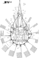
- the swather according to the invention comprises a frame (1) which can be hung on a tractor not shown by means of a drawbar (2).
- the latter is articulated at the front end of the frame (1) by means of axes (41) substantially perpendicular to the direction of advance (A).
- Said frame consists of a frame (42) of substantially triangular shape and a support (43) which is equipped with load-bearing wheels (3) which roll on the ground.
- the frame (42) of the frame (1) supports a swath rotor (4) consisting in particular of a ring (5) on which are mounted arms (6) directed outwards. Each of these arms (6) carries working forks (7) at its outer end.
- the frame (42) carries four rollers (8) which are arranged in a substantially horizontal plane for guiding the ring (5). Each of these rollers (8) has a V-shaped groove (44) on its periphery.
- the ring (5) has a square section. It is guided in the grooves (44) by means of its internal faces (45 and 46) (see Figure 5). Said ring (5) can rotate on these rollers (8) around a geometric axis (9) located at its center. This geometric axis (9) is vertical or slightly inclined relative to the vertical.
- the ring (5) carries at substantially regular intervals on its periphery supports (10) for the fork arms (6).
- These supports (10) consist of plates with two edges (11 and 12) directed upwards. They are welded to the ring (5) and carry two bearings (13 and 14) in which the arms extend (6). Between these arms (6) and said bearings (13 and 14) there is provided a slight clearance, so that they can pivot around their respective longitudinal axes (15).
- the frame (42) of the frame (1) also supports a control member (16) of the fork arms (6) which makes them pivot around the longitudinal axes (15) during the rotation of the ring (5) .
- This control member (16) is located at least partially near said ring (5), so that the middle of the rotor (4) is free. It is advantageously located completely outside the ring (5).
- this control member (16) is constituted by a belt (17). It could also be constituted by a chain or another similar piece.
- This belt (17) is guided by means of three pulleys (18, 19 and 20) which are mounted on supports (21, 22 and 23) integral with the frame (1). It passes in addition on legs (24) substantially vertical which are integral with the ring (5).
- the pulley (18) is located at the front of the ring (5), near the most advanced end of the frame (1). It is mounted on a motor shaft which can be driven in rotation for example from the PTO shaft of the tractor. To this end, this drive shaft is linked to a bevel torque located in a casing (25) with a second shaft (26) which can be connected to the PTO shaft by an intermediate drive shaft.
- the two pulleys (19 and 20) are located one on the left side and the other on the right side of the frame (42). Their supports (22 and 23) can be moved along this frame (42) and be fixed in different places.
- the belt (17) passes over the tabs (24) of the ring (5) on the rear part of the latter. Thanks to contact with a large number of these tabs (24), it drives the ring (5) in rotation about the geometric axis (9) when it is itself driven by the pulley (18).
- each fork-carrying arm (6) Between the belt (17) and each fork-carrying arm (6) are arranged means (27) which actuate said arms (6).
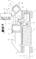
- These means (27) are constituted by a crank (28) and a return mechanism (29) (see Figure 5).
- Each crank (28) consists of a substantially vertical lever (30) which is located at the level of the belt (17), a substantially horizontal arm (31) and a socket (32). The latter is pivotally mounted on a substantially vertical axis (33) which is integral with the corresponding support (10).
- the socket (32) has a toothed sector (34) which is oriented downwards and which extends over approximately one third of its periphery.
- On each fork arm (6) is fixed a ring (35) by means of a pin (36).
- This ring (35) has a toothed sector (37) which is directed upwards and which extends over approximately one third of its periphery. This sector (37) meshes with the aforementioned sector (34) with which it forms an angle of approximately 90 °.
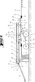
- On each fork arm (6) is additionally mounted an angular action spring (38). This rests on the one hand on the pin (36) and on the other hand on the support (10). It thus exerts pressure on the fork arm (6) which tends to rotate it around its longitudinal axis (15), so that it occupies the raking position shown in FIG. 3.
- the support (10) has on its edge (12) which is directed upwards two stops (39 and 40) which limit the movements of the crank (28).
- the cranks (28) are pressed against the first stops (39) by the springs (38). These act on the arms (6) and, through the two toothed sectors (37 and 34), on said cranks (28). In this position, the forks (7) of the arms (6) are substantially vertical.
- the belt (17) is in contact with the levers (30) of the cranks (28). It moves the latter around their pivot axes (33) and presses them against the second stops (40).
- the toothed sectors (34 and 37) then rotate the fork arms (6) by approximately 90 ° against the springs (38), so that the forks (7) are substantially horizontal.
- the support (43) of the frame (1) passes inside the ring (5). It is articulated on the frame (42) by means of an axis (47) substantially perpendicular to the direction of advance (A).
- a hydraulic cylinder (48) is articulated by means of an axis (49) on longitudinal members (50) of the support (43) and by means of an axis (51) on plates (52) which are integral with a crosspiece (53) of the frame (42).
- This hydraulic cylinder (48) makes it possible to move the frame (42) relative to the support (43), around the articulation axis (47). This displacement causes a variation in the distance from the ground of the frame (42) and the rotor (4).
- the wheels (3) of the support (43) are mounted in pairs on pendulums (54). These are articulated on the support (43) by means of axes (55) substantially perpendicular to the direction of advance (A).
- the support (43) also comprises a lever (56) which extends upwards beyond its axis of articulation (47) with the frame (42).
- the drawbar (2) comprises, near its end which is linked to the frame (42), a lever (57) which extends upwards beyond the axis of articulation (41) with said frame (42 ).
- These two levers (56 and 57) are substantially parallel to each other and have substantially the same length.
- a rod (58) which is substantially parallel to the frame (42) connects the two levers (56 and 57). This rod (58) is articulated on the lever (57) of the drawbar (2) by means of an axis (59) and on the lever (56) of the support (43) by means of a second axis (60).
- the embodiment according to Figure 6 differs from the above example in that the frame (1) carries a rail (61) for guiding the cranks (28) on the front part of the ring (5).
- This rail (61) is substantially parallel to said ring (5). he extends at such a distance from this ring (5) that it keeps the cranks (28) in contact with the first stops (39).
- This rail (61) eliminates the springs (38) and ensures greater stability of the arms (6) and forks (7) in the raking position.
- the frame (42) and the rotor (4) of the machines according to the two examples described above are lowered by means of the hydraulic cylinder (48) until the forks (7) which are directed downwards touch the ground. Thanks to the parallelogram arrangement of the frame (42) of the rod (58) and of the levers (56 and 57), said frame (42) and the rotor (4) remain practically parallel to the ground during their movements in height. . In addition, the drawbar attachment clevis (2) remains substantially at the same level.
- the machine is then pulled in the direction of travel (A) using the tractor.
- the belt (17) is driven in the direction of the arrow (F) by the pulley (18). It in turn drives the ring (5) with the fork arms (6) in the same direction.
- the forks (7) are then raised horizontally, so that they deposit the raked plants in the form of a swath ( Figure 4). These forks (7) remain in the raised position over the entire rear part of the ring (5). Then, the belt (17) is guided by the pulley (20) so that it moves away from the ring (5) and releases the cranks (28). Simultaneously, the springs (38) rotate the arms (6) about their longitudinal axes (15). Said arms (6) drive the corresponding cranks (28) via the toothed sectors (37 and 34) until they meet the first stops (39). In this position, the forks (7) are again in the raking position ( Figure 3). In the example according to FIG. 6, it is the rail (61) which makes the cranks (26) pivot so that they make the arms (6) and the forks (7) pivot in the raking position.
- the user stops the rotation of the rotor (4). Then it actuates the hydraulic cylinder (48) so that it lifts the frame (42) with the rotor (4) and moves the forks (7) away from the ground.
- the fork arms (6) can then be partially disassembled to reduce the width of the machine.
Landscapes
- Life Sciences & Earth Sciences (AREA)
- Environmental Sciences (AREA)
- Agricultural Machines (AREA)
- Harvester Elements (AREA)
- Manipulator (AREA)
- Catching Or Destruction (AREA)
- Forklifts And Lifting Vehicles (AREA)
Applications Claiming Priority (2)
| Application Number | Priority Date | Filing Date | Title |
|---|---|---|---|
| FR9408882A FR2722365B1 (fr) | 1994-07-13 | 1994-07-13 | Machine de fenaison, notamment une andaineuse de vegetaux a bras porte-fourches commandes |
| FR9408882 | 1994-07-13 |
Publications (2)
| Publication Number | Publication Date |
|---|---|
| EP0692185A1 true EP0692185A1 (de) | 1996-01-17 |
| EP0692185B1 EP0692185B1 (de) | 2001-01-10 |
Family
ID=9465498
Family Applications (1)
| Application Number | Title | Priority Date | Filing Date |
|---|---|---|---|
| EP95440041A Expired - Lifetime EP0692185B1 (de) | 1994-07-13 | 1995-07-04 | Heuwerbungsmaschine, namentlich ein Schwader mit gesteuerten Zinkentragarmen |
Country Status (5)
| Country | Link |
|---|---|
| US (1) | US5586421A (de) |
| EP (1) | EP0692185B1 (de) |
| AT (1) | ATE198527T1 (de) |
| DE (1) | DE69519829T2 (de) |
| FR (1) | FR2722365B1 (de) |
Cited By (1)
| Publication number | Priority date | Publication date | Assignee | Title |
|---|---|---|---|---|
| CN104956859A (zh) * | 2015-06-12 | 2015-10-07 | 中南林业科技大学 | 一种多功能农业干草收集器 |
Families Citing this family (11)
| Publication number | Priority date | Publication date | Assignee | Title |
|---|---|---|---|---|
| FR2746577B1 (fr) * | 1996-03-29 | 1998-05-29 | Kuhn Sa | Machine de fenaison comportant un dispositif de protection deplacable |
| FR2754136B1 (fr) * | 1996-10-03 | 1999-01-22 | Kuhn Sa | Machine de fenaison comportant un chassis compose de plusieurs troncons articules entre eux |
| FR2756137B1 (fr) * | 1996-11-26 | 1999-01-22 | Kuhn Sa | Machine de fenaison, notamment une andaineuse avec un deflecteur d'andainage reglage automatiquement dans differentes positions |
| US6272826B1 (en) | 1999-04-29 | 2001-08-14 | Sitrex S.R.L. | Method and apparatus for positioning a hay rake |
| US6865873B2 (en) * | 2002-06-21 | 2005-03-15 | Sitrex S.R.L. | Pull type V-shaped hay rake |
| US6834488B2 (en) | 2002-11-22 | 2004-12-28 | Sitrex S.R.L. | Towable hay rake with an automatic steering mechanism |
| US7377093B2 (en) * | 2005-10-19 | 2008-05-27 | Cnh America Llc | Rotary crop inverter |
| FR2987223B1 (fr) * | 2012-02-29 | 2014-03-28 | Kuhn Sa | Rotor d'une machine de fenaison muni de bras en deux parties reliees par un dispositif de liaison perfectionne |
| US9839180B2 (en) * | 2015-06-19 | 2017-12-12 | Sam Esch | Windrow forming agricultural rake assembly |
| GB201811406D0 (en) * | 2018-07-12 | 2018-08-29 | Agco Feucht Gmbh | Towed agricultural implement |
| AU2025200532B1 (en) * | 2025-01-27 | 2025-05-01 | Duane Gargan | Apparatus for use in Agriculture |
Citations (6)
| Publication number | Priority date | Publication date | Assignee | Title |
|---|---|---|---|---|
| CH474207A (de) * | 1968-07-05 | 1969-06-30 | Bucher Guyer Ag Masch | Heuerntemaschine |
| FR1589179A (de) * | 1967-09-28 | 1970-03-23 | ||
| CH490786A (de) * | 1968-05-27 | 1970-05-31 | Bucher Guyer Ag Masch | Heuerntemaschine |
| DE1457953A1 (de) * | 1962-09-27 | 1970-07-02 | Deere & Co | Heubearbeitungsmaschine mit mindestens einem Paar quer zur Fahrtrichtung nebeneinander angeordneter Kreisel |
| GB1220337A (en) | 1966-12-23 | 1971-01-27 | Texas Industries Inc | Improvements in or relating to hay-making machines |
| DE2150555A1 (de) * | 1971-10-11 | 1973-04-19 | Strautmann & Soehne | Heuwerbungsmaschine |
Family Cites Families (14)
| Publication number | Priority date | Publication date | Assignee | Title |
|---|---|---|---|---|
| CH508332A (de) * | 1969-04-16 | 1971-06-15 | Kuhn Freres & Cie | Heuerntemaschine |
| NL7514498A (nl) * | 1975-12-12 | 1977-06-14 | Lely Nv C Van Der | Landbouwmachine. |
| FR2339330A1 (fr) * | 1976-01-30 | 1977-08-26 | Kuhn Sa | Machine de fenaison pour le fanage et pour l'andainage |
| FR2342639A1 (fr) * | 1976-03-05 | 1977-09-30 | Kuhn Sa | Dispositif permettant la modification de l'angle de piquage des toupies d'une machine agricole du type faneuse-andaineuse |
| FR2549342B1 (fr) * | 1983-07-19 | 1987-10-02 | Kuhn Sa | Machine de fenaison perfectionnee pour le fanage |
| FR2576744B1 (fr) * | 1985-02-06 | 1988-06-17 | Kuhn Sa | Perfectionnement aux jupes flexibles pour deplacer des produits se trouvant sur le sol et machines agricoles equipees de telles jupes |
| FR2582186B1 (fr) * | 1985-05-21 | 1989-05-05 | Kuhn Sa | Perfectionnement aux machines de fenaison munies de plusieurs roues rateleuses |
| FR2613177B1 (fr) * | 1987-04-01 | 1991-06-28 | Kuhn Sa | Machine de fenaison |
| FR2632810B2 (fr) * | 1987-11-17 | 1991-08-30 | Kuhn Sa | Machine de fenaison avec au moins une roue rateleuse equipee de bras porte-outils commandes |
| FR2631775B1 (fr) * | 1988-05-26 | 1991-10-11 | Kuhn Sa | Machine agricole comportant au moins un rotor entraine en rotation durant le travail |
| FR2632155B1 (fr) * | 1988-06-03 | 1991-10-11 | Kuhn Sa | Machine de fenaison comportant un rotor pour andainer |
| FR2644320B1 (fr) * | 1989-03-20 | 1992-05-07 | Kuhn Sa | Machine agricole avec au moins un rotor pour deplacer des produits se trouvant sur le sol |
| FR2648310B1 (fr) * | 1989-06-16 | 1991-09-20 | Kuhn Sa | Machine agricole pour l'andainage, comportant des bras porte-outils repliables |
| FR2678804B1 (fr) * | 1991-07-11 | 1998-09-18 | Kuhn Sa | Machine de fenaison comportant au moins une roue rateleuse, un dispositif de protection et un deflecteur reglable. |
-
1994
- 1994-07-13 FR FR9408882A patent/FR2722365B1/fr not_active Expired - Fee Related
-
1995
- 1995-07-04 DE DE69519829T patent/DE69519829T2/de not_active Expired - Fee Related
- 1995-07-04 EP EP95440041A patent/EP0692185B1/de not_active Expired - Lifetime
- 1995-07-04 AT AT95440041T patent/ATE198527T1/de not_active IP Right Cessation
- 1995-07-13 US US08/501,808 patent/US5586421A/en not_active Expired - Fee Related
Patent Citations (6)
| Publication number | Priority date | Publication date | Assignee | Title |
|---|---|---|---|---|
| DE1457953A1 (de) * | 1962-09-27 | 1970-07-02 | Deere & Co | Heubearbeitungsmaschine mit mindestens einem Paar quer zur Fahrtrichtung nebeneinander angeordneter Kreisel |
| GB1220337A (en) | 1966-12-23 | 1971-01-27 | Texas Industries Inc | Improvements in or relating to hay-making machines |
| FR1589179A (de) * | 1967-09-28 | 1970-03-23 | ||
| CH490786A (de) * | 1968-05-27 | 1970-05-31 | Bucher Guyer Ag Masch | Heuerntemaschine |
| CH474207A (de) * | 1968-07-05 | 1969-06-30 | Bucher Guyer Ag Masch | Heuerntemaschine |
| DE2150555A1 (de) * | 1971-10-11 | 1973-04-19 | Strautmann & Soehne | Heuwerbungsmaschine |
Cited By (1)
| Publication number | Priority date | Publication date | Assignee | Title |
|---|---|---|---|---|
| CN104956859A (zh) * | 2015-06-12 | 2015-10-07 | 中南林业科技大学 | 一种多功能农业干草收集器 |
Also Published As
| Publication number | Publication date |
|---|---|
| US5586421A (en) | 1996-12-24 |
| DE69519829D1 (de) | 2001-02-15 |
| FR2722365A1 (fr) | 1996-01-19 |
| EP0692185B1 (de) | 2001-01-10 |
| FR2722365B1 (fr) | 1996-09-20 |
| ATE198527T1 (de) | 2001-01-15 |
| DE69519829T2 (de) | 2001-07-12 |
Similar Documents
| Publication | Publication Date | Title |
|---|---|---|
| CA2226656C (fr) | Machine agricole de coupe perfectionnee | |
| FR2628596A1 (fr) | Faucheuse a entrainement direct | |
| FR2754136A1 (fr) | Machine de fenaison comportant un chassis compose de plusieurs troncons articules entre eux | |
| EP0692185B1 (de) | Heuwerbungsmaschine, namentlich ein Schwader mit gesteuerten Zinkentragarmen | |
| EP1290936B1 (de) | Heuwerbungsmaschine | |
| FR2663189A1 (fr) | Machine de fenaison pour l'andainage, comportant au moins deux roues rateleuses. | |
| EP0772969B1 (de) | Heuwerbungsmaschine mit mindestens einem Rotor zum Schwaden | |
| EP0514302B1 (de) | Verbesserter Pflanzenschwader | |
| EP1142468A1 (de) | Heuwerbungsmaschine | |
| EP0614604B1 (de) | Heuwerbungsmaschine | |
| EP0954956B1 (de) | Heuwerbungsmaschine | |
| FR2664127A1 (fr) | Machine agricole, notamment une andaineuse de vegetaux, a largeur de travail reglable. | |
| EP0680688B1 (de) | Heuwerbungsmaschine, insbesondere ein Schwader für Futter | |
| EP0797913B1 (de) | Heuwerbungsmaschine | |
| EP0857413B1 (de) | Heuwerbungsmaschine | |
| EP0554200B1 (de) | Heuwerbungsmaschine mit einem mit gesteuerten Stützrädern versehenen Rahmen | |
| EP1926363B1 (de) | Heuwerbungsmaschine mit einklappbaren seitlichen bauteilen | |
| FR2707450A1 (fr) | Machine de fenaison avec des rotors de fanage ou d'andainage munis de roues d'appui au sol. | |
| EP0692184B1 (de) | Heuwerbungsmaschine, namentlich ein Schwader, mit einem verbesserten Steuerorgan der Zinkentragarme | |
| FR2687892A1 (fr) | Andaineur de fourrage avec un mecanisme pour interrompre l'entrainement du rotor. | |
| EP0654209B1 (de) | Heuwerbungsmaschine | |
| EP1269826B1 (de) | Heuwerbungsmaschine | |
| EP0914766B1 (de) | Heuwerbungsmachine | |
| FR2798817A1 (fr) | Machine de fenaison, notamment une andaineuse avec plusieurs rotors s'appuyant sur le sol au moyen de roues porteuses | |
| FR2699044A1 (fr) | Machine de fenaison avec des roues de transport déplaçables en hauteur. |
Legal Events
| Date | Code | Title | Description |
|---|---|---|---|
| PUAI | Public reference made under article 153(3) epc to a published international application that has entered the european phase |
Free format text: ORIGINAL CODE: 0009012 |
|
| AK | Designated contracting states |
Kind code of ref document: A1 Designated state(s): AT DE DK FR IT NL |
|
| 17P | Request for examination filed |
Effective date: 19960624 |
|
| 17Q | First examination report despatched |
Effective date: 19990318 |
|
| GRAG | Despatch of communication of intention to grant |
Free format text: ORIGINAL CODE: EPIDOS AGRA |
|
| GRAG | Despatch of communication of intention to grant |
Free format text: ORIGINAL CODE: EPIDOS AGRA |
|
| GRAH | Despatch of communication of intention to grant a patent |
Free format text: ORIGINAL CODE: EPIDOS IGRA |
|
| GRAH | Despatch of communication of intention to grant a patent |
Free format text: ORIGINAL CODE: EPIDOS IGRA |
|
| GRAA | (expected) grant |
Free format text: ORIGINAL CODE: 0009210 |
|
| AK | Designated contracting states |
Kind code of ref document: B1 Designated state(s): AT DE DK FR IT NL |
|
| PG25 | Lapsed in a contracting state [announced via postgrant information from national office to epo] |
Ref country code: NL Free format text: LAPSE BECAUSE OF FAILURE TO SUBMIT A TRANSLATION OF THE DESCRIPTION OR TO PAY THE FEE WITHIN THE PRESCRIBED TIME-LIMIT Effective date: 20010110 Ref country code: IT Free format text: LAPSE BECAUSE OF FAILURE TO SUBMIT A TRANSLATION OF THE DESCRIPTION OR TO PAY THE FEE WITHIN THE PRE;WARNING: LAPSES OF ITALIAN PATENTS WITH EFFECTIVE DATE BEFORE 2007 MAY HAVE OCCURRED AT ANY TIME BEFORE 2007. THE CORRECT EFFECTIVE DATE MAY BE DIFFERENT FROM THE ONE RECORDED.SCRIBED TIME-LIMIT Effective date: 20010110 |
|
| REF | Corresponds to: |
Ref document number: 198527 Country of ref document: AT Date of ref document: 20010115 Kind code of ref document: T |
|
| RTI1 | Title (correction) |
Free format text: HAYMAKING MACHINE, ESPECIALLY A SWATHER WITH CONTROLLED FORK-CARRYING ARMS |
|
| REF | Corresponds to: |
Ref document number: 69519829 Country of ref document: DE Date of ref document: 20010215 |
|
| PG25 | Lapsed in a contracting state [announced via postgrant information from national office to epo] |
Ref country code: DK Free format text: LAPSE BECAUSE OF FAILURE TO SUBMIT A TRANSLATION OF THE DESCRIPTION OR TO PAY THE FEE WITHIN THE PRESCRIBED TIME-LIMIT Effective date: 20010410 |
|
| NLV1 | Nl: lapsed or annulled due to failure to fulfill the requirements of art. 29p and 29m of the patents act | ||
| PLBE | No opposition filed within time limit |
Free format text: ORIGINAL CODE: 0009261 |
|
| STAA | Information on the status of an ep patent application or granted ep patent |
Free format text: STATUS: NO OPPOSITION FILED WITHIN TIME LIMIT |
|
| 26N | No opposition filed | ||
| PGFP | Annual fee paid to national office [announced via postgrant information from national office to epo] |
Ref country code: AT Payment date: 20040624 Year of fee payment: 10 |
|
| PGFP | Annual fee paid to national office [announced via postgrant information from national office to epo] |
Ref country code: DE Payment date: 20040629 Year of fee payment: 10 |
|
| PG25 | Lapsed in a contracting state [announced via postgrant information from national office to epo] |
Ref country code: AT Free format text: LAPSE BECAUSE OF NON-PAYMENT OF DUE FEES Effective date: 20050704 |
|
| PG25 | Lapsed in a contracting state [announced via postgrant information from national office to epo] |
Ref country code: DE Free format text: LAPSE BECAUSE OF NON-PAYMENT OF DUE FEES Effective date: 20060201 |
|
| PGFP | Annual fee paid to national office [announced via postgrant information from national office to epo] |
Ref country code: FR Payment date: 20140721 Year of fee payment: 20 |