EP0692448A1 - Véhicule de manutention de matériel - Google Patents
Véhicule de manutention de matériel Download PDFInfo
- Publication number
- EP0692448A1 EP0692448A1 EP95304952A EP95304952A EP0692448A1 EP 0692448 A1 EP0692448 A1 EP 0692448A1 EP 95304952 A EP95304952 A EP 95304952A EP 95304952 A EP95304952 A EP 95304952A EP 0692448 A1 EP0692448 A1 EP 0692448A1
- Authority
- EP
- European Patent Office
- Prior art keywords
- engine
- vehicle
- output shaft
- vehicle according
- transfer mechanism
- Prior art date
- Legal status (The legal status is an assumption and is not a legal conclusion. Google has not performed a legal analysis and makes no representation as to the accuracy of the status listed.)
- Withdrawn
Links
- 238000001816 cooling Methods 0.000 claims description 8
- 230000009347 mechanical transmission Effects 0.000 claims description 5
- 230000005540 biological transmission Effects 0.000 claims description 2
- 238000013016 damping Methods 0.000 claims description 2
- 239000000446 fuel Substances 0.000 claims description 2
- 230000001419 dependent effect Effects 0.000 claims 6
- 230000004048 modification Effects 0.000 description 11
- 238000012986 modification Methods 0.000 description 11
- 239000000463 material Substances 0.000 description 5
- 239000002826 coolant Substances 0.000 description 2
- 238000000034 method Methods 0.000 description 2
- 230000004308 accommodation Effects 0.000 description 1
- 238000002485 combustion reaction Methods 0.000 description 1
- 230000004438 eyesight Effects 0.000 description 1
- 239000011521 glass Substances 0.000 description 1
- 230000002706 hydrostatic effect Effects 0.000 description 1
- 238000002955 isolation Methods 0.000 description 1
- 239000000203 mixture Substances 0.000 description 1
- 230000010355 oscillation Effects 0.000 description 1
- 230000001141 propulsive effect Effects 0.000 description 1
- 230000001681 protective effect Effects 0.000 description 1
- 239000000126 substance Substances 0.000 description 1
- 238000009423 ventilation Methods 0.000 description 1
Images




Classifications
-
- B—PERFORMING OPERATIONS; TRANSPORTING
- B66—HOISTING; LIFTING; HAULING
- B66F—HOISTING, LIFTING, HAULING OR PUSHING, NOT OTHERWISE PROVIDED FOR, e.g. DEVICES WHICH APPLY A LIFTING OR PUSHING FORCE DIRECTLY TO THE SURFACE OF A LOAD
- B66F9/00—Devices for lifting or lowering bulky or heavy goods for loading or unloading purposes
- B66F9/06—Devices for lifting or lowering bulky or heavy goods for loading or unloading purposes movable, with their loads, on wheels or the like, e.g. fork-lift trucks
- B66F9/065—Devices for lifting or lowering bulky or heavy goods for loading or unloading purposes movable, with their loads, on wheels or the like, e.g. fork-lift trucks non-masted
- B66F9/0655—Devices for lifting or lowering bulky or heavy goods for loading or unloading purposes movable, with their loads, on wheels or the like, e.g. fork-lift trucks non-masted with a telescopic boom
Definitions
- This invention relates to a material-handling vehicle of the kind, hereinafter referred to as the "kind specified”, comprising a structure having ground engageable propulsion means, a loader arm mounted at the rear of the structure for up and down swinging movement, an operator's cab disposed on the structure on one side of the loader arm longitudinal axis and an engine mounted on the structure to provide power for said swinging movement of the arm and propulsion of the vehicle.
- EP-B-0375705 discloses another such vehicle in which the loader arm in a fully lowered position is partly accommodated in a well disposed between the operator's cab and a housing in which an engine to provide power for swinging movement of the loader arm and propulsion of the vehicle is disposed with the engine being arranged longitudinally of the vehicle so that the crank shaft of the engine extends parallel to the longitudinal axis of the vehicle.
- the loader arm is disposed below a horizontal plane containing the bottom of a side window in the operator's cab which faces transversely across the vehicle, again so as not to interfere with the view of the operator in this direction.
- Such a vehicle configuration enables the vehicle to be made smaller than the vehicle of US-E-30021 and enables the overall height of the vehicle to be reduced.
- DE-A-2739537 discloses another such vehicle but in which the engine of the vehicle is disposed transversely, so that its crankshaft extends perpendicular to the longitudinal axis of the vehicle, and the loader arm, in its lowered position, is disposed so that the loader arm is entirely above the top of the engine and its associated housing. Accordingly the vehicle is unprovided with any well so that in a lowered position the loader arm extends alongside the operator's cab substantially above the bottom of a side window therein so that the driver's view transversely of the vehicle is obstructed.
- An object of the invention is to provide a material-handling vehicle of the kind specified whereby the above mentioned problems are overcome or are reduced.
- the engine is located on one side of the loader arm longitudinal axis and the engine has an output shaft and the engine is transversely disposed with its output shaft transverse to the vehicle.
- the loader arm may extend forwardly parallel to a vertical plane containing a longitudinal axis of the vehicle.
- the engine may be located on the opposite side of the loader arm longitudinal axis to the cab and the engine is spaced from the cab to define a well between the cab and the engine in which the arm, in a lowered position, can be at least partly accommodated.
- the engine may be disposed on the opposite side of the loader arm longitudinal axis to the cab.
- the engine may be disposed in a housing.
- the engine may be located on the same side of the loader arm to the cab with the engine disposed at least partly beneath the cab.
- a housing may be provided, disposed on the opposite side of the loader arm to the cab, and a well may be provided, between the cab and the housing, in which the arm, in a lowered position, can be at least partly accommodated.
- the housing may house a cooling means for the engine or other auxiliary means of the engine and/or vehicle such as a fuel or oil tank.
- the first and/or the second more specific aspects of the invention may have the following features.
- the output shaft of the engine may be perpendicular to the longitudinal axis of the vehicle. However, if desired, the output shaft of the engine may be arranged at an angle other than perpendicular to the longitudinal axis of the vehicle.
- the output shaft may be at an angle in the range 35° - 55° to the longitudinal axis of the vehicle and preferably at 45° to the longitudinal axis.
- the output shaft may be provided by the crankshaft of the engine.
- the structure may have a front end and a rear end with said longitudinal axis of the vehicle extending therebetween and the ground engageable propulsion means being disposed equi-distant from, and on opposite sides of, said longitudinal axis.
- the loader arm may carry a material handling implement at its front end so that the material handling implement is disposed in front of the front of the structure when the arm is in its lowermost position.
- the cab may have a side window which faces transversely across the vehicle at right angles to the longitudinal axis of the vehicle.
- the loader arm may be mounted on the structure at a position which is not more than a predetermined distance above a horizontal plane passing through the highest part of the engine or the engine.
- a first predetermined distance we mean about 350mm above and preferably about 300mm above or at or below the height of said highest point.
- the loader arm at the position alongside the highest point of the engine, may be not more than a second predetermined distance above said horizontal plane.
- a second predetermined distance we mean about 450mm above and preferably about 65mm above and may be at or below the height of said highest point.
- the structure may comprise a pair of spaced fore and aft extending frame members which are preferably parallel to each other.
- the ground engageable propulsion means may be driven via a mechanical transmission.
- the mechanical transmission may comprise a gearbox disposed underneath the well.
- the gearbox may have an input shaft which extends generally parallel to the longitudinal axis of the vehicle and at least one output shaft which also extends generally parallel to the longitudinal axis of the vehicle and there being a transfer mechanism having an input shaft to transfer the drive from the transversely extending output shaft of the engine to the longitudinally extending input shaft to the gearbox.
- the transfer mechanism may comprise an input shaft and an output shaft disposed at an angle to each other, the input shaft being connected to the output shaft of the engine and the output shaft being connected to the input shaft to the gearbox and the input and output shafts of the transfer mechanism being connectable in torque transmitting relationship by a gear set which may comprise a bevel gear set.
- the input shaft of the transfer mechanism is inclined to the output shaft of the transfer mechanism at a corresponding angle.
- the input shaft of the transfer mechanism may be arranged at 90° to the output shaft of the transfer mechanism.
- the input shaft of the transfer mechanism may be arranged at 45° to the output shaft of the transfer mechanism, or at another appropriate angle depending on the angle of the output shaft of the engine to the longitudinal axis of the vehicle.
- the ground engageable propulsion means may comprise a pair of ground engageable wheels disposed adjacent the front of the structure and a pair of rear ground engageable wheels adjacent the rear of the structure.
- the wheels of the front pair may be driven from a first output shaft of the gearbox whilst the wheels of the rear pair may be driven by a second output shaft of the gearbox through differential gear means.
- the transfer mechanism may be provided with damping means between the engine output shaft and the transfer mechanism input shaft to reduce engine induced vibrations or resonance.
- the engine and/or transfer mechanism and/or gearbox may be provided with mounting means to accommodate torsional movement and as necessary lateral, axial, vertical movement of both engine and gearbox.
- the engine, transfer mechanism and gear box may be rigidly connected together.
- the transfer mechanism comprises a housing having a first mounting face, which faces transversely outwardly of the vehicle, to which a mounting face of the engine is connected, and a second mounting face facing in the fore and aft direction of the vehicle, to which a mounting face of the gear box is connected.
- the engine, transfer mechanism and gear box may each have at least one mounting means whereby the coupled together components are mounted on the vehicle.
- the mounting means are vibration isolating mountings.
- the housing of the transfer mechanism may have a first and a second mounting means disposed on opposite sides of the axis of rotation of the output shaft of the engine and preferably carried by one of the fore and aft extending frame members.
- the gear box may have a mounting on the side of the gear box which is on the opposite side of the fore and aft axis of the vehicle to the engine and preferably carried by the other of the fore and aft extending frame members.
- At least one of the engine and the gearbox may be movable relative to the transfer mechanism and the engine output shaft being flexibly connected to in input shaft of the transfer mechanism and/or the output shaft of the transfer mechanism being flexibly connected to the input shaft of the gearbox.
- the vehicle according to the present invention may be provided with a relatively short wheel base because of the relatively short longitudinal extent of the transversely mounted engine permitting the wheels to be closer together than as hitherto have been provided.
- the provision of a mechanical transmission is less costly than a hydrostatic transmission.
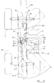
- a material-handling vehicle is indicated generally at 10 and comprises a main structure 11 having a front end 12 and a rear end 13 with a longitudinal axis X-X extending between the front and rear ends.
- the structure 11 comprises a pair of spaced parallel frame members 14, 15 held in spaced parallel relationship by cross members including a rear torsion box 11 a , a deck plate 11 b and front torsion box 11 c .
- Each frame member 14, 15 has an upper surface 21, 22 respectively. At the front and rear the frame members 14, 15 have generally upright parts 24, 25 respectively whilst on their undersides they have a lower surface 26, 27 respectively.
- the right-hand frame member 15 has an upwardly relieved part 28 to provide clearance for an engine and transfer mechanism, as hereinafter to be described.
- a front axle 30 is mounted on the frame members 14, 15 at the front end thereof whilst a rear axle 31 is mounted to the frame members 15 towards the rear thereof.
- the axles 30, 31 are of conventional type carrying at their opposite ends front wheels 33 and rear wheels 34 respectively. Both the front wheels 33 and both rear wheels 34 are pivotable relative to their associated axis about a vertical steering axis V for steering movement of the vehicle, as shown in chain dotted line in Figure 3.
- At least one of the axles may be mounted relative to the frame members 14, 15 for oscillation about a longitudinally extending axis.
- Each axle 30, 31 is provided with a differential 35, 36 respectively of conventional form, the differentials being driven by propeller shafts 37, 38 respectively from front and rear output shafts 39, 40 respectively of a change speed gearbox 41 incorporating, by virtue of being bolted thereto, a torque converter 42.
- the input and output shafts and change speed gear carrying shafts of the gear box 41 extend parallel to the longitudinal axis X-X.
- the torque connector may be omitted or provided in some other suitable manner in the drive train.
- the change speed gearbox 41 is mounted on the frame members 14, 15 so as to be disposed therebetween and disposed so that the rear end face 41 a of the gearbox is at a position approximately midway between transverse axes R F , R R respectively extending horizontally through the axes V and the centre of propulsive rotation of each wheel 33, 34.
- An operator's cab 50 is mounted on the frame member 14 by vibration isolating mounts 51 so that the cab 50 is supported on one side of the longitudinal axis X-X of the vehicle.
- the cab 50 has a front window 57 a , a rear window 57 b and two side windows 57 c , 57 d , the window 57 c facing transversely across the machine.
- the or each window may be provided with a transparent closure element such as glass, or may be open, or may be provided with a protective element such as a grille or bars.
- a driver's seat, steering wheel and other controls, not shown, are provided in the cab and the cab is provided with an access door or opening on the side in which the window 57 d is provided.
- a loader arm 60 is pivotally mounted, by means of an axle member 61, between the frame members 14, 15 at the rear 13 of the vehicle for pivotal up and down swinging movement about a horizontal axis H.
- the loader arm 60 is telescopic and comprises a rear outer section 62 which is pivotally connected to the frame members 14 and 15 by the axle 61 and a forward inner member 63 which is telescopically slidable with the section 62 under the control of hydraulic rams in conventional manner.
- the part 63 At its front end the part 63 is provided with a downwardly and forwardly extending part 64 adapted to carry a material handling implement such as a loader bucket or lifting forks or other desired material handling means.
- the loader arm may have more than two telescopically slidable sections or may not be telescopic.
- the loader arm 60 When the loader arm 60 is in its lowermost position, as shown in the Figures, it lies in a well 70 of a minimum width W which is greater than the width of the loader arm and provided between the cab 50 and the frame member 15.
- An internal combustion engine 71 is disposed on the opposite side of the frame member 15 to the well 70 and thus is disposed on the opposite side of the longitudinal axis X-X of the vehicle to the cab 50.
- the engine 71 is, in the present example, a four cylinder diesel engine having a crankshaft 71 c rotatable about an axis C-C which is perpendicular to the longitudinal axis X-X.
- the engine 71 is mounted on the frame member 15 by means of a mounting frame 74 carried by the frame members 14, 15 and having a transversely outwardly extending part 75 supported in cantilever from the frames 14, 15.
- the frame 74 carries vibration isolating mounts 76 by which the engine 71 is mounted on the vehicle and further vibration isolating mounts 76 a by which the gear box 41 is mounted on the vehicle.
- the engine is disposed in a housing 72, the top 72 a of which at one side extends generally transversely away from the frame member 15 at substantially the top thereof and is inclined downwardly, as best shown in Figure 2.
- the housing 72 has a generally vertical side surface 72 b and, at the front and rear, downwardly and rearwardly and downwardly and extending forwardly front and rear end faces 72 c , 72 d respectively.
- the housing may be of a different configuration than that described hereinbefore and may be wholly or partly omitted.
- a transfer mechanism 80 mounted in a transfer box 82 having a first extension part 82 a having a first mounting face 83 bolted to the inwardly facing end face 85 of the engine 71 and a second extension part 82 b having a second mounting face 84 bolted to a first torque converter housing part 42 a which is bolted to the rearwardly facing end 41 a of the gearbox 41.
- Rotatably mounted within the transfer box 82 is an input shaft 86 which is connected to the crankshaft 71 c of the engine and an output shaft 87 which is connected to the input shaft 88 of the gearbox.
- the input and output shafts 86, 87 have bevel gears 86 a , 87 a respectively fixed relative thereto and which are interengaged to transmit torque between the engine and the gearbox therethrough.
- the output shaft 87 has an extension 87 a which drives a hydraulic pump 80 a bolted to the transfer box 82.
- the torque converter 42 is housed by virtue of the transfer box 82 having an integral extension part 82 b which provides a second torque converter housing part and which co-operates with the first torque converter housing part 42 a to provide a housing for the torque converter 42
- the torque converter housing part 82 b may be separate from and bolted to the transfer box 82.
- the torque converter may be housed in any other desired manner so as to be operatively disposed between the gearbox and the transfer mechanism or at another suitable disposition in the drive path such as between the engine and the transfer mechanism.
- the transfer box 82 is connected to the mounting frame by a vibration isolating mount 77 but if desired the transfer box may be supported solely by virtue of its connection to the engine and the gearbox.
- a cooling radiator 90 Disposed in front of the engine within the housing 72 is a cooling radiator 90 through which coolant of the engine 71 is circulated through pipes, not shown, and the radiator 90 is provided with an by a hydraulically operated fan 91, or, if desired, by an electrically or mechanically operated fan to cause flow of cooling air of the radiator, suitable ventilation openings may be provided in the housing 72 for flow of such air. If desired the radiator may be positioned at another position on the vehicle, such as adjacent to the rear thereof.
- the engine is disposed wholly to the rear of a mid-point between the axes R F and R R and the gearbox substantially wholly to the front of such mid-point, is desired the engine may be positioned in any desired longitudinal position between the wheels and the gearbox may be positioned at a desired longitudinal position on the machine. If desired, the gearbox may be mounted to the rear of the engine.
- the distance between the outside of frame members 14, 15 may be less than 30% of the overall width of the machine excluding the wheels and may be, for example, in the range 24% to 27%.
- the axis H lies in the same horizontal plane as the highest point of the engine 71, i.e. the rocker box in the illustrated example, but may be below this height or above this height, for example, about 300mm above or even higher, such as 350mm above.
- the highest point of the loader arm 60 including any external component such as an operating ram, at the position alongside the highest point of the engine is about 65mm above the highest point of the engine but may be at or below the highest point or above this height, for example 400mm above or higher, such as 450mm above.
- the arm in its lowest position may be horizontal or may extend forwardly and downwardly.
- FIG 5 illustrates a modification of the vehicle described with reference to Figures 1 to 4 in which the vehicle is provided with a mounting frame 174 which extends in cantilever from the frame members 14 and 15 on opposite sides thereof so that the frame carries the engine on the outside of the frame 15 and carries the cab 50 on the outside of the frame 14.
- the modification of Figure 3 is as described previously.
- FIG 6 in which the same reference numerals have been used to refer to corresponding parts as were used in Figures 1 - 4, shows an alternative modification in which the gearbox and transfer box are supported as described hereinbefore from a mounting frame 274 which is disposed, in this case, substantially wholly between the frame members 14, 15 and the engine is supported in cantilever by virtue of the inwardly facing end mounting face 85 of the engine, being bolted to the first mounting face 83 of the transfer case 82 with one or more vibration isolating mounts or other torsion control means 276 being provided between the engine and the side frame 15 or a lug 277 provided on the frame 274.
- a mounting frame 274 which is disposed, in this case, substantially wholly between the frame members 14, 15 and the engine is supported in cantilever by virtue of the inwardly facing end mounting face 85 of the engine, being bolted to the first mounting face 83 of the transfer case 82 with one or more vibration isolating mounts or other torsion control means 276 being provided between the engine and the side
- FIGs 7 and 8 in which the same reference numerals have been used to refer to corresponding parts as were used in Figures 1 - 4, show a further, preferred, modification in which the drive assembly comprising the engine 71, transfer mechanism 82 and a gearbox 41, is mounted using three mounts on the main structure 11.
- the gearbox 41 is mounted relative to the frame member 14 by a conventional vibration isolating mount 376 disposed between the inwardly facing surface 314 of the frame member 14 and the adjacent surface 341 of the gearbox 41.
- a second mount 376 a is provided between the outwardly facing surface 315 of the other frame member 15 and a lug 300 formed integrally with the extension part 82 a of the transfer box 82.
- a third mount 376 b is provided between the frame member 15 and a lug 301 formed integrally with the first extension part 82 a of the transfer box 82 and disposed on the opposite side of the axis of rotation of the output shaft of the engine to the mount 376 a .
- the engine is supported in cantilever as described in connection with Figure 6 by virtue of an inwardly facing mounting face 85 of the engine being connected to the first mounting face 83 of the transfer box 82.
- the engine 71 is so arranged that its output shaft 71 c is transverse to the longitudinal axis X-X of the vehicle and the axis of rotation of the output shaft 71 is inclined at, or substantially at, 90° to the axis X-X.
- the axis of rotation of the output shaft of the engine may be arranged transverse to the axis X-X at an angle other than perpendicular to the longitudinal axis.
- the axis of rotation of the output shaft may be at 45° to the longitudinal axis or at least in the range 35° - 55°.
- FIG 9 there is shown a vehicle 10' which is in most respects, is generally similar to the vehicle 10 of Figure 1 to 8. Similar parts are labelled with the same reference numerals but with a prime sign added.
- the engine 71' is mounted transversely but so that its output shaft 71 c ' extends generally at 45° to the longitudinal axis X-X of the vehicle 10'.
- the transfer mechanism indicated at 82' includes an input shaft 86' which also extends generally at 45° to the longitudinal axis X-X of the vehicle, and the transfer mechanism 82' further comprises an output shaft 87' which extends generally parallel to the axis X-X, and connects with the input shaft 88' of change speed gearbox 41'.
- the input and output shafts 86', 87' of the transfer mechanism 82' each have respective bevel gears 86 a ' and 87 a ' and thus drive can be transmitted from the output shaft 71 c ' of the engine 71' to the change speed gearbox 41'.
- the cooling radiator indicated at 90' is mounted adjacent to the engine 71' towards the front end of the vehicle 10' and the engine 71' is mounted on a mounting frame 74' by means of vibration isolating mounts 76'.
- the gear box 41' is mounted by means of a vibration isolating mount 76 a ' on the frame member 15' and the transfer box 82' by a vibration isolating mount 77' on the mounting frame 74'.
- the output shaft 71 c ' of the engine 71' subtends an angle of about 45° to the longitudinal axis X-X, the output shaft 71 c ' extending towards the rear axle 31' of the vehicle 10'.
- the output shaft 71 c ' of the vehicle subtends an angle of about 45° to the longitudinal axis X-X of the vehicle, but the output shaft 71 c ' extends towards the front axle 30' of the vehicle.
- bevel gears 86 a ' and 87 a ' of the transfer mechanism 82' are arranged oppositely to the corresponding gears of the mechanism 82' in Figure 9.
- the change speed gearbox 41' in Figure 10 is arranged slightly forward in the vehicle compared with the gearbox 41' of the vehicle shown in Figure 9.
- the vibration isolation mounts 76' for the engine 71' are arranged as shown, as are the mounts 76 a ' and 77' for the gear box 41' and transfer box 82' respectively; the mounting 77' being carried on a bracket on the frame member 14'.
- the vehicle 10' shown in Figure 11 is generally identical to the vehicles in Figures 9 and 10 and corresponding parts are again labelled with the same reference numbers.
- the output shaft 71 c ' of the engine 71' is arranged similarly to the output shaft of the engine of the vehicle 10' of Figure 9 i.e. towards the front axle 30' of the vehicle.
- the change speed gearbox 41' is arranged rearwardly of the vehicle, closer to the rear axle 31' than the gearbox 41' of the vehicle of Figure 10.
- input shaft 88' of the gearbox 41' extends forwardly of the vehicle rather rearwardly as is the case with the arrangements shown in Figures 9 and 10.
- the output shaft 87' of the transfer mechanism 82' thus extends rearwardly of the vehicle.
- the cooling radiator indicated at 90' is located rearwardly of engine 71' rather than forwardly of the engine 71' as in the arrangements of Figures 9 and 10.
- the engine mountings are shown at 76', the gear box mounting at 76 a ', being provided on a bracket on the frame member 14' and the transfer box mounting at 77' being provided on the mounting frame 74'.
- the vehicle of Figure 12 is again generally identical to the vehicles of Figures 9, 10 and 11 and corresponding parts are again labelled with the same reference numerals.
- the engine 71' is so arranged that its output shaft 71 c ' extends at 45° to the longitudinal axis X-X of the vehicle 10' towards the rear axle 31' of the vehicle, as with the arrangement of Figure 9.
- the change speed gearbox 41' is arranged towards the rear axle 31'.
- the input shaft 88' to the change speed gearbox 41' extends forwardly towards the front axle 30' of the vehicle 10' with corresponding changes to the configuration of the transfer mechanism 82'.
- the engine mountings are shown at 76', the gear box mounting at 76 a ', being provided on a bracket on the frame member 14' and the transfer box mounting at 77' being provided on a bracket on the frame member 15'.
- the output shaft 71 c ' of the engine 71' has in each case extended generally at 45° to the longitudinal axis X-X of the vehicle, in another arrangement, the respective shaft 71 c ' could extend transversely at other than 45° such as within the range 35° - 55°, or at any other desired angle, with suitable changes to the configuration of the transfer mechanism 82' and the positionings of the respective engine mountings 76'.
- Figures 13 and 14 show diagrammatically a modification of the vehicle shown in Figures 1 to 4.
- the vehicle of Figures 13 and 14 is similar to that in Figures 1 to 4 and hence the same reference numerals have been used for Figures 13 and 14 as were used with reference to Figures 1 to 4 to refer to corresponding parts.
- the vehicle of Figures 13 and 14 differs from that of Figures 1 to 4 only in that the engine 71 is, in this embodiment, disposed on the same side of the longitudinal axis X-X of the vehicle as the cab 50 and is disposed beneath the cab 50. That is to say, beneath a bottom wall part 50 a of the cab 50 which separates the interior of the cab 50 which contains the driver D and controls C from the exterior below the driver D and controls C. As shown, the bottom wall part 50 a is not rectilinear and includes upwardly extending portions which extend between parts of the wall 50 a which are at different levels. Although as illustrated, these upwardly extending portions are inclined from the horizontal and the vertical, if desired they may, of course, extend vertically and still be regarded as part of the floor of the cab.
- the cooling radiator 90 is, in this embodiment, disposed on the opposite side of the longitudinal axis X-X of the vehicle to the cab and is disposed in a housing 72 which is similar in configuration to the housing 72 of the embodiment of Figures 1 to 4. If desired, the radiator may be positioned at other location of the vehicle and the housing 72 may be absent or its configuration suitably modified. Where a housing the same as or similar to the housing 72, or indeed any other housing, is provided for the cooling radiator, or for any other component of the machine, between the front and rear wheels 33, 34 on the opposite side of the axis X-X to the cab 50, then a well similar to the well described hereinbefore is provided.
- the radiator 90 is supplied with a coolant of the engine 71 via pipes, not shown, and as in the previously described embodiment the radiator may be provided with a hydraulically operated fan or an electrically operated fan.
- the gearbox 41 of the present embodiment is the same as the gearbox 41 of the embodiment of Figures 1 to 4, as is its driving connection to the wheels 34, 33.
- the transfer mechanism 80 is the same as the transfer mechanism described with reference to Figures 1 to 4 but is, of course, orientated at 180° to the orientation described with reference to Figures 1 to 4.
- Figures 9 to 12 may also, in principle, be applied to the embodiment of Figures 13 and 14 particularly, for example, the embodiment of Figure 10, where the engine would be disposed substantially in a rear part of the cab, but the embodiments shown in, for example, Figure 9 or Figure 12 would necessitate repositioning the driver in the cab so that the floor of the cab may provide space therebeneath for an engine disposed in the configuration analogous to that shown in these Figures.
- a part of the engine may be disposed outwardly of the plan outline of the cab.
- a part of the fly wheel housing of the engine may be disposed outwardly of said plan outline of the cab towards the loader arm for connection to the transfer mechanism 80.
- the wheels on the front axle may have a different track to the wheels of the rear axle, whilst the wheels of an axle are equivalent from, and on opposite sides of, the longitudinal axis of the vehicle.
- ground engageable propulsion means may comprise endless tracks.
Landscapes
- Engineering & Computer Science (AREA)
- Transportation (AREA)
- Structural Engineering (AREA)
- Civil Engineering (AREA)
- Life Sciences & Earth Sciences (AREA)
- Geology (AREA)
- Mechanical Engineering (AREA)
- Arrangement Or Mounting Of Propulsion Units For Vehicles (AREA)
- Arrangement Of Transmissions (AREA)
- Shovels (AREA)
Applications Claiming Priority (6)
| Application Number | Priority Date | Filing Date | Title |
|---|---|---|---|
| GB9414382A GB9414382D0 (en) | 1994-07-15 | 1994-07-15 | Material-handling vehicle |
| GB9414382 | 1994-07-15 | ||
| GB9415506A GB9415506D0 (en) | 1994-07-15 | 1994-08-01 | Material-handling vehicle |
| GB9415506 | 1994-08-01 | ||
| GB9505963 | 1995-03-23 | ||
| GBGB9505963.0A GB9505963D0 (en) | 1995-03-23 | 1995-03-23 | Material-handling vehicle |
Publications (1)
| Publication Number | Publication Date |
|---|---|
| EP0692448A1 true EP0692448A1 (fr) | 1996-01-17 |
Family
ID=27267281
Family Applications (1)
| Application Number | Title | Priority Date | Filing Date |
|---|---|---|---|
| EP95304952A Withdrawn EP0692448A1 (fr) | 1994-07-15 | 1995-07-14 | Véhicule de manutention de matériel |
Country Status (4)
| Country | Link |
|---|---|
| US (1) | US5836733A (fr) |
| EP (1) | EP0692448A1 (fr) |
| JP (1) | JP3807760B2 (fr) |
| CA (1) | CA2153955C (fr) |
Cited By (19)
| Publication number | Priority date | Publication date | Assignee | Title |
|---|---|---|---|---|
| WO1997046478A1 (fr) * | 1996-06-05 | 1997-12-11 | New Holland Uk Limited | Automate telescopique |
| FR2759662A1 (fr) * | 1997-02-20 | 1998-08-21 | Fdi Sambron | Chassis de chariot elevateur, chariot elevateur comportant un tel chassis et procede de fabrication d'un tel chariot |
| GB2327077A (en) * | 1997-07-08 | 1999-01-13 | Bamford Excavators Ltd | Compact load handling vehicle |
| EP0876932A3 (fr) * | 1997-05-09 | 1999-10-20 | Caterpillar Inc. | Arrangement de transfert de puissance pour engin de travail |
| EP1024108A1 (fr) | 1999-01-27 | 2000-08-02 | Sambron | Dispositif de contrôle de déplacement d'une structure portante d'engin roulant |
| FR2797625A1 (fr) | 1999-08-18 | 2001-02-23 | Sambron | Dispositif de correction de devers pour plate-forme a deux essieux |
| EP1084986A1 (fr) * | 1999-09-16 | 2001-03-21 | J.C. Bamford Excavators Limited | Véhicule de manutention de matériaux |
| EP0945396A3 (fr) * | 1998-03-27 | 2002-04-17 | MERLO S.P.A. Industria Metalmeccanica | Véhicule avec une flèche ayant un moteur disposé obliquement par rapport à l'axe longitudinal du véhicule |
| EP0945397A3 (fr) * | 1998-03-27 | 2002-04-17 | MERLO S.P.A. Industria Metalmeccanica | Véhicule à flèche ayant une prise de force entraínée par une transmission mécanique |
| EP0945395A3 (fr) * | 1998-03-27 | 2002-04-17 | Merlo S.P.A. Industria Metalmeccanica | Véhicule à flèche de levage, pouvant être utilisé comme une machine d' agriculture |
| GB2369810A (en) * | 2000-12-09 | 2002-06-12 | Caterpillar Inc | Engine cooling arrangement in a work machine with an extensible arm |
| US6439827B1 (en) | 1997-07-08 | 2002-08-27 | J C Bamford Excavators Limited | Load handling vehicle |
| EP1362824A1 (fr) * | 2002-05-15 | 2003-11-19 | Komatsu Utility Europe S.p.A. | Véhicule élévateur à bras de levage télescopique |
| FR2849009A1 (fr) * | 2002-12-18 | 2004-06-25 | Modules Associes | Chariot semi-industriel, a portee variable, pour la manutention de materiaux |
| IT201900004833A1 (it) * | 2019-04-01 | 2020-10-01 | Dieci S R L | Veicolo per la movimentazione di carichi |
| EP3718954A1 (fr) * | 2019-04-01 | 2020-10-07 | Dieci S.r.l. | Vehicule pour la manipulation des charges |
| EP3718953A1 (fr) * | 2019-04-01 | 2020-10-07 | Dieci S.r.l. | Vehicule pour la manipulation des charges |
| EP3702312B1 (fr) | 2019-03-01 | 2023-12-13 | J.C. Bamford Excavators Limited | Machine de travail |
| GB2623565A (en) * | 2022-10-20 | 2024-04-24 | Bamford Excavators Ltd | A material handling machine |
Families Citing this family (30)
| Publication number | Priority date | Publication date | Assignee | Title |
|---|---|---|---|---|
| WO1998032928A1 (fr) * | 1997-01-28 | 1998-07-30 | Manitou Bf S.A. | Perfectionnement aux tracto-pelles |
| US5944130A (en) * | 1997-11-04 | 1999-08-31 | Caterpillar Inc. | Trunnion mounted drive train arrangement |
| GB2336255B (en) | 1998-04-08 | 2002-03-13 | Gen Domestic Appliances Ltd | Cooking appliance energy regulator |
| GB9807538D0 (en) * | 1998-04-09 | 1998-06-10 | Bamford Excavators Ltd | Material-handling vehicle |
| GB9807532D0 (en) | 1998-04-09 | 1998-06-10 | Bamford Excavators Ltd | Material-handling vehicle |
| GB0015579D0 (en) * | 2000-06-27 | 2000-08-16 | Bamford Excavators Ltd | Load handling vehicle |
| USD461831S1 (en) | 2000-09-07 | 2002-08-20 | Deere & Company | Telehandler |
| JP2002362174A (ja) | 2001-04-03 | 2002-12-18 | Komatsu Ltd | ホイール式走行作業車両 |
| US6904994B2 (en) | 2001-11-16 | 2005-06-14 | Caterpillar Inc | Horizontal transmission and oil system for telehandlers |
| KR100556658B1 (ko) * | 2002-03-22 | 2006-03-07 | 히다치 겡키 가부시키 가이샤 | 자주식 작업 기계 |
| KR101029376B1 (ko) * | 2010-10-11 | 2011-04-15 | 대호 (주) | 트랙터 |
| USD668271S1 (en) * | 2011-10-31 | 2012-10-02 | J.C. Bamford Excavators Limited | Telehandler |
| USD723240S1 (en) * | 2013-11-08 | 2015-02-24 | Cnh Industrial America Llc | Material handling vehicle |
| US12017526B2 (en) | 2018-06-19 | 2024-06-25 | Kubota Corporation | Work machine |
| JP7226705B2 (ja) * | 2018-06-19 | 2023-02-21 | 株式会社クボタ | 作業機 |
| USD903223S1 (en) * | 2019-03-26 | 2020-11-24 | J.C. Bamford Excavators Limited | Telehandler |
| CA206853S (en) * | 2021-04-02 | 2023-07-20 | Manitou Italia Srl | Telescopic handler |
| USD1013586S1 (en) | 2021-04-02 | 2024-02-06 | Manitou Italia S.R.L. | Protective grille for vehicle |
| USD1020812S1 (en) | 2021-11-18 | 2024-04-02 | Manitou Italia S.R.L. | Cabin for telescopic lifter |
| USD998835S1 (en) | 2021-11-18 | 2023-09-12 | Manitou Italia S.R.L. | Headlight for telescopic lifter |
| USD1005637S1 (en) | 2021-11-18 | 2023-11-21 | Manitou Italia S.R.L. | Turret for telescopic lifter |
| USD1026047S1 (en) | 2021-11-19 | 2024-05-07 | Manitou Italia S.R.L. | Visor for telescopic lifter |
| USD1060439S1 (en) | 2021-11-19 | 2025-02-04 | Manitou Italia S.R.L. | Console with hand controls for telescopic lifter |
| USD1048115S1 (en) | 2021-11-19 | 2024-10-22 | Manitou Italia S.R.L. | Cabin hood for a vehicle with a telescopic lifter |
| USD1070223S1 (en) | 2021-12-29 | 2025-04-08 | Manitou Italia S.R.L. | Part of cabin for telescopic lifter |
| USD1063289S1 (en) | 2021-12-29 | 2025-02-18 | Manitou Italia S.R.L. | Ladder for telescopic lifter |
| USD1103224S1 (en) | 2022-02-02 | 2025-11-25 | Manitou Italia S.R.L. | Handles for telescopic lifter |
| USD1060923S1 (en) | 2022-02-08 | 2025-02-04 | Manitou Italia S.R.L. | Platform for telescopic lifter |
| USD1086632S1 (en) | 2022-02-08 | 2025-07-29 | Manitou Italia S.R.L. | Cabin hood for a vehicle with a telescopic lifter |
| USD995578S1 (en) | 2022-02-08 | 2023-08-15 | Manitou Italia S.R.L. | Cabin for telescopic lifter |
Citations (7)
| Publication number | Priority date | Publication date | Assignee | Title |
|---|---|---|---|---|
| DE2128073A1 (de) * | 1971-06-05 | 1972-12-07 | Hfm Hohenloher Fahrzeuge- Und Maschinenvertrieb Gmbh, 7183 Langenburg | Fahrbarer Kran mit Stapelvorrichtung |
| DE2739537A1 (de) | 1976-09-03 | 1978-03-09 | Loed Corp | Schwenkgabelanordnung fuer verladeausruestungen |
| USRE30021E (en) | 1973-05-21 | 1979-06-05 | Loed Corporation | Material handling machine |
| GB2161784A (en) * | 1984-07-20 | 1986-01-22 | Mcconnel F W Ltd | Handling or working vehicle |
| EP0325064A1 (fr) * | 1987-12-18 | 1989-07-26 | Manitou Bf | Amélioration à la stabilité des chariots élévateurs à bras télescopique |
| EP0375705A1 (fr) | 1987-07-27 | 1990-07-04 | Merlo Ind Metalmecc | Chariot elevateur a bras elevateur telescopique. |
| EP0656315A1 (fr) * | 1993-12-01 | 1995-06-07 | Manitou Bf | Chariot élévateur à bras télescopique |
Family Cites Families (8)
| Publication number | Priority date | Publication date | Assignee | Title |
|---|---|---|---|---|
| JPS5332511A (en) * | 1976-09-03 | 1978-03-27 | Loed Corp | Cargo handling vehicle |
| DE2847033B1 (de) * | 1978-10-28 | 1980-03-20 | Jungheinrich Kg | Fahrwerksantrieb fuer elektrisch getriebene mobile Arbeitsmaschinen |
| US4449606A (en) * | 1980-07-18 | 1984-05-22 | Veda, Inc. | Vehicle frame assembly |
| FR2514051A1 (fr) * | 1981-10-05 | 1983-04-08 | Komatsu Mfg Co Ltd | Pelle mecanique a commande hydraulique |
| DD240869A1 (de) * | 1985-09-12 | 1986-11-19 | Fortschritt Veb K | Antriebsblock fuer arbeitsmaschinen mit quergestelltem antriebsmotor |
| CA2009968C (fr) * | 1990-02-13 | 1996-06-25 | Giovanni Bentivoglio | Chariot-elevateur a fourche et mat de charge |
| JP3040860B2 (ja) * | 1991-09-02 | 2000-05-15 | ジヤトコ・トランステクノロジー株式会社 | ミッドシップ4輪駆動用横置きトランスミッション |
| US5463915A (en) * | 1993-10-21 | 1995-11-07 | General Motors Corporation | Drive-reversing gearing for an engine driven transmission |
-
1995
- 1995-07-14 EP EP95304952A patent/EP0692448A1/fr not_active Withdrawn
- 1995-07-14 JP JP20157795A patent/JP3807760B2/ja not_active Expired - Lifetime
- 1995-07-14 CA CA002153955A patent/CA2153955C/fr not_active Expired - Lifetime
- 1995-07-14 US US08/502,493 patent/US5836733A/en not_active Expired - Lifetime
Patent Citations (7)
| Publication number | Priority date | Publication date | Assignee | Title |
|---|---|---|---|---|
| DE2128073A1 (de) * | 1971-06-05 | 1972-12-07 | Hfm Hohenloher Fahrzeuge- Und Maschinenvertrieb Gmbh, 7183 Langenburg | Fahrbarer Kran mit Stapelvorrichtung |
| USRE30021E (en) | 1973-05-21 | 1979-06-05 | Loed Corporation | Material handling machine |
| DE2739537A1 (de) | 1976-09-03 | 1978-03-09 | Loed Corp | Schwenkgabelanordnung fuer verladeausruestungen |
| GB2161784A (en) * | 1984-07-20 | 1986-01-22 | Mcconnel F W Ltd | Handling or working vehicle |
| EP0375705A1 (fr) | 1987-07-27 | 1990-07-04 | Merlo Ind Metalmecc | Chariot elevateur a bras elevateur telescopique. |
| EP0325064A1 (fr) * | 1987-12-18 | 1989-07-26 | Manitou Bf | Amélioration à la stabilité des chariots élévateurs à bras télescopique |
| EP0656315A1 (fr) * | 1993-12-01 | 1995-06-07 | Manitou Bf | Chariot élévateur à bras télescopique |
Cited By (29)
| Publication number | Priority date | Publication date | Assignee | Title |
|---|---|---|---|---|
| WO1997046478A1 (fr) * | 1996-06-05 | 1997-12-11 | New Holland Uk Limited | Automate telescopique |
| FR2759662A1 (fr) * | 1997-02-20 | 1998-08-21 | Fdi Sambron | Chassis de chariot elevateur, chariot elevateur comportant un tel chassis et procede de fabrication d'un tel chariot |
| EP0876932A3 (fr) * | 1997-05-09 | 1999-10-20 | Caterpillar Inc. | Arrangement de transfert de puissance pour engin de travail |
| US6439827B1 (en) | 1997-07-08 | 2002-08-27 | J C Bamford Excavators Limited | Load handling vehicle |
| GB2327077A (en) * | 1997-07-08 | 1999-01-13 | Bamford Excavators Ltd | Compact load handling vehicle |
| GB2327077B (en) * | 1997-07-08 | 2000-12-13 | Bamford Excavators Ltd | Load handling vehicle |
| DE19830373B4 (de) * | 1997-07-08 | 2009-09-10 | J.C. Bamford Excavators Ltd., Rocester | Lastenhandhabungsfahrzeug |
| KR100598239B1 (ko) * | 1998-03-27 | 2006-07-07 | 머로 스파 인더스트리아 메탈메카니카 | 농기구로서 이용될 수 있는, 리프팅 부움을 가지는 차량 |
| EP0945396A3 (fr) * | 1998-03-27 | 2002-04-17 | MERLO S.P.A. Industria Metalmeccanica | Véhicule avec une flèche ayant un moteur disposé obliquement par rapport à l'axe longitudinal du véhicule |
| EP0945397A3 (fr) * | 1998-03-27 | 2002-04-17 | MERLO S.P.A. Industria Metalmeccanica | Véhicule à flèche ayant une prise de force entraínée par une transmission mécanique |
| EP0945395A3 (fr) * | 1998-03-27 | 2002-04-17 | Merlo S.P.A. Industria Metalmeccanica | Véhicule à flèche de levage, pouvant être utilisé comme une machine d' agriculture |
| EP1024108A1 (fr) | 1999-01-27 | 2000-08-02 | Sambron | Dispositif de contrôle de déplacement d'une structure portante d'engin roulant |
| FR2797625A1 (fr) | 1999-08-18 | 2001-02-23 | Sambron | Dispositif de correction de devers pour plate-forme a deux essieux |
| US6382899B1 (en) | 1999-09-16 | 2002-05-07 | J.C. Bamford Excavators Ltd. | Material-handling vehicle |
| EP1084986A1 (fr) * | 1999-09-16 | 2001-03-21 | J.C. Bamford Excavators Limited | Véhicule de manutention de matériaux |
| GB2369810A (en) * | 2000-12-09 | 2002-06-12 | Caterpillar Inc | Engine cooling arrangement in a work machine with an extensible arm |
| US6910544B2 (en) | 2000-12-09 | 2005-06-28 | Caterpillar Inc | Work machine arrangement |
| GB2369810B (en) * | 2000-12-09 | 2004-07-14 | Caterpillar Inc | Work machine arrangement |
| EP1362824A1 (fr) * | 2002-05-15 | 2003-11-19 | Komatsu Utility Europe S.p.A. | Véhicule élévateur à bras de levage télescopique |
| WO2004056691A1 (fr) * | 2002-12-18 | 2004-07-08 | Modules Associes | Vehicule de la manutention de materiaux |
| FR2849009A1 (fr) * | 2002-12-18 | 2004-06-25 | Modules Associes | Chariot semi-industriel, a portee variable, pour la manutention de materiaux |
| EP3702312B1 (fr) | 2019-03-01 | 2023-12-13 | J.C. Bamford Excavators Limited | Machine de travail |
| IT201900004833A1 (it) * | 2019-04-01 | 2020-10-01 | Dieci S R L | Veicolo per la movimentazione di carichi |
| EP3718952A1 (fr) * | 2019-04-01 | 2020-10-07 | Dieci S.r.l. | Vehicule pour la manutention des charges |
| EP3718954A1 (fr) * | 2019-04-01 | 2020-10-07 | Dieci S.r.l. | Vehicule pour la manipulation des charges |
| EP3718953A1 (fr) * | 2019-04-01 | 2020-10-07 | Dieci S.r.l. | Vehicule pour la manipulation des charges |
| GB2623565A (en) * | 2022-10-20 | 2024-04-24 | Bamford Excavators Ltd | A material handling machine |
| GB2623565B (en) * | 2022-10-20 | 2025-04-16 | Bamford Excavators Ltd | A material handling machine |
| US12584286B2 (en) | 2022-10-20 | 2026-03-24 | J.C. Bamford Excavators Limited | Material handling machine |
Also Published As
| Publication number | Publication date |
|---|---|
| CA2153955C (fr) | 2005-01-11 |
| US5836733A (en) | 1998-11-17 |
| CA2153955A1 (fr) | 1995-09-24 |
| JP3807760B2 (ja) | 2006-08-09 |
| JPH08118966A (ja) | 1996-05-14 |
Similar Documents
| Publication | Publication Date | Title |
|---|---|---|
| CA2153955C (fr) | Vehicule de manutention | |
| US6318485B1 (en) | Tractor | |
| US10005357B2 (en) | Working vehicle | |
| GB2291384A (en) | Material-handling vehicle with a loader arm and transverse engine | |
| US20020139597A1 (en) | Wheel type traveling and operating vehicle | |
| US8511711B2 (en) | Carrier frame of a utility vehicle | |
| EP0949187A2 (fr) | Véhicule de manutention de matériaux | |
| US6382899B1 (en) | Material-handling vehicle | |
| US6514031B1 (en) | Material-handling vehicle | |
| EP0949185B1 (fr) | Véhicule de manutention de matériaux | |
| US4746145A (en) | Chassis frame for rider-controlled working vehicle | |
| EP1312498B1 (fr) | Système horizontal de transmission et de lubrification pour grue téléscopique | |
| EP1348889B1 (fr) | Transmission pour véhicule de transport de matière | |
| US6079937A (en) | Material-handling vehicle | |
| EP0949186A2 (fr) | Véhicule de manutention de matériaux | |
| JP2572886B2 (ja) | 作業車の機体フレーム構造 | |
| JP7788980B2 (ja) | 作業車 | |
| JP7792881B2 (ja) | 作業車 | |
| EP3299264A1 (fr) | Tracteur à chenilles | |
| US6910547B1 (en) | Mounting arrangement of an automobile drive unit having a combustion engine and a transmission | |
| JPH0143984Y2 (fr) | ||
| CA1054947A (fr) | Configuration de vehicule | |
| JP3897113B2 (ja) | モアトラクタ | |
| Sickman et al. | White Farm Equipments 4-150 Field Boss | |
| JPH02231228A (ja) | 横置エンジン車 |
Legal Events
| Date | Code | Title | Description |
|---|---|---|---|
| PUAI | Public reference made under article 153(3) epc to a published international application that has entered the european phase |
Free format text: ORIGINAL CODE: 0009012 |
|
| AK | Designated contracting states |
Kind code of ref document: A1 Designated state(s): AT BE CH DE DK ES FR GB GR IT LI LU NL PT SE |
|
| 17P | Request for examination filed |
Effective date: 19960321 |
|
| STAA | Information on the status of an ep patent application or granted ep patent |
Free format text: STATUS: THE APPLICATION HAS BEEN WITHDRAWN |
|
| 18W | Application withdrawn |
Withdrawal date: 19970501 |