EP0692632A2 - Pompe à entraînement magnétique - Google Patents
Pompe à entraînement magnétique Download PDFInfo
- Publication number
- EP0692632A2 EP0692632A2 EP95104900A EP95104900A EP0692632A2 EP 0692632 A2 EP0692632 A2 EP 0692632A2 EP 95104900 A EP95104900 A EP 95104900A EP 95104900 A EP95104900 A EP 95104900A EP 0692632 A2 EP0692632 A2 EP 0692632A2
- Authority
- EP
- European Patent Office
- Prior art keywords
- pump
- magnet
- laboratory
- magnetic stirrer
- rotor
- Prior art date
- Legal status (The legal status is an assumption and is not a legal conclusion. Google has not performed a legal analysis and makes no representation as to the accuracy of the status listed.)
- Ceased
Links
Images


Classifications
-
- F—MECHANICAL ENGINEERING; LIGHTING; HEATING; WEAPONS; BLASTING
- F04—POSITIVE - DISPLACEMENT MACHINES FOR LIQUIDS; PUMPS FOR LIQUIDS OR ELASTIC FLUIDS
- F04D—NON-POSITIVE-DISPLACEMENT PUMPS
- F04D13/00—Pumping installations or systems
- F04D13/02—Units comprising pumps and their driving means
- F04D13/021—Units comprising pumps and their driving means containing a coupling
- F04D13/024—Units comprising pumps and their driving means containing a coupling a magnetic coupling
-
- F—MECHANICAL ENGINEERING; LIGHTING; HEATING; WEAPONS; BLASTING
- F04—POSITIVE - DISPLACEMENT MACHINES FOR LIQUIDS; PUMPS FOR LIQUIDS OR ELASTIC FLUIDS
- F04C—ROTARY-PISTON, OR OSCILLATING-PISTON, POSITIVE-DISPLACEMENT MACHINES FOR LIQUIDS; ROTARY-PISTON, OR OSCILLATING-PISTON, POSITIVE-DISPLACEMENT PUMPS
- F04C15/00—Component parts, details or accessories of machines, pumps or pumping installations, not provided for in groups F04C2/00 - F04C14/00
- F04C15/0057—Driving elements, brakes, couplings, transmission specially adapted for machines or pumps
- F04C15/008—Prime movers
-
- F—MECHANICAL ENGINEERING; LIGHTING; HEATING; WEAPONS; BLASTING
- F04—POSITIVE - DISPLACEMENT MACHINES FOR LIQUIDS; PUMPS FOR LIQUIDS OR ELASTIC FLUIDS
- F04C—ROTARY-PISTON, OR OSCILLATING-PISTON, POSITIVE-DISPLACEMENT MACHINES FOR LIQUIDS; ROTARY-PISTON, OR OSCILLATING-PISTON, POSITIVE-DISPLACEMENT PUMPS
- F04C2/00—Rotary-piston machines or pumps
- F04C2/08—Rotary-piston machines or pumps of intermeshing-engagement type, i.e. with engagement of co-operating members similar to that of toothed gearing
- F04C2/12—Rotary-piston machines or pumps of intermeshing-engagement type, i.e. with engagement of co-operating members similar to that of toothed gearing of other than internal-axis type
- F04C2/14—Rotary-piston machines or pumps of intermeshing-engagement type, i.e. with engagement of co-operating members similar to that of toothed gearing of other than internal-axis type with toothed rotary pistons
- F04C2/18—Rotary-piston machines or pumps of intermeshing-engagement type, i.e. with engagement of co-operating members similar to that of toothed gearing of other than internal-axis type with toothed rotary pistons with similar tooth forms
Definitions
- the invention relates to a laboratory pump for liquids with at least one pump housing having an inlet opening and an outlet opening, with at least one pump rotor rotating therein and with a drive for the pump rotor, the pump rotor being connected directly or indirectly to a magnet via a gear or even as Magnet is formed.
- Laboratory pumps have been known for a long time and are used in large numbers, for example to pump or circulate liquid in experimental setups. These known pumps can be used particularly advantageously for feeding or circulating the bath liquid from thermostatically controlled, generally double-walled vessels.
- the problem here is that the liquid in the double wall gradually loses its temperature, so that the medium in this vessel could not be kept at its temperature if the bath liquid were not repeatedly reheated. For this purpose, it is circulated and reheated outside the double-walled vessel, the circulation being controlled by temperature sensors and / or thermostats.
- the known pumps have one have their own drive motor and therefore require a construction that is comparatively complex and expensive for laboratory operation.
- an electric motor connected to the mains is usually provided as the drive motor, so that appropriate protective measures against impermissibly high contact voltages, such as, for example, connecting a transformer or encapsulating the electric motor, in particular with respect to the pump chamber, are required.
- a device for stirring or pumping a medium is already known from CH-668 919 A5.
- This device has a freely rotatable magnetic rotor which can exert a stirring or pumping effect when rotating, a feed device delivering phase-shifted alternating currents and energizing an electromagnetic drive device which has an annular core made of ferromagnetic material which has at least two fixed magnet coil segments in the Kind of a toroidal core is wound, whereby the electromagnetic drive device generates a rotating magnetic field that rotates the rotor.
- a special holder is required, which must be opened in order to be able to use the drive device for the different installations. So that the device can work as a pump, a tube must be inserted in the ring formed by the drive device, which can lead the medium to be pumped in a certain direction. A specially shaped magnetic rotor inside this tube has the required pumping effect.
- this device is only after appropriate conversions either suitable for stirring or for pumping and requires additional holders for the mixing vessel when used as a stirrer.
- a magnetic stirrer is provided as the drive for the pump rotor and that the pump with its pump housing can be connected to the magnetic stirrer at least in the direction of extension of a mounting plate having a footprint such that the drive magnetic field of the magnetic stirrer is in magnetic coupling with the Magnet of the pump.
- the pump not only the drive unit of a stirrer that works with a magnetic rod, but also a complete magnetic stirrer that is available in large numbers in most laboratories is provided for driving the laboratory pump, so that the pump not only does not require its own drive motor and is accordingly simple and can be constructed inexpensively, but can also be connected in a simple manner to the existing magnetic stirrer on its mounting surface in order to be already functional.
- the pump only needs to be placed on the mounting surface of the magnetic stirrer and connected to it in order to be brought into drive connection. If it is removed again, the magnetic stirrer is immediately available in its original form as a stirring device. It is therefore not only the magnetic drive device of a magnetic stirrer that is used as the drive for the pump itself.
- the pump housing can be of particularly simple construction, since the shaft of the pump rotor is not an external drive shaft out and must be sealed against the pump housing.
- the magnetic stirrers present in laboratories are given an additional function by the pump according to the invention, so that these comparatively expensive devices can be used even better.
- the pump rotor is designed as a vane pump wheel.
- the liquid can then be sucked in axially at the top of the pump impeller and conveyed further radially.
- the pump rotor has symmetrically designed delivery vanes so that the pump, for example in the case of magnetic stirrers with a switchable direction of rotation, can be driven equally in different directions of rotation.
- the pump can be heated, in particular has a heatable housing wall.
- the pump is then particularly suitable for circulating the bath liquid from thermostatically controlled vessels.
- the bath liquid can both be circulated by the pump and brought to the desired temperature with the heater integrated, for example, in the pump, so that overall there is an easy-to-use device in which the connection of an external heater can be omitted.
- a further development of the invention provides that the magnetic stirrer has a heating plate and that a heat-transferring surface is provided on the contact surface between the magnetic stirrer and the pump housing.
- a pump not only the drive of the magnetic stirrer, but also its heating plate can advantageously be used for conveying and tempering liquids. Since the wall of the pump housing touching the heating plate is heated by the heating plate, the pump itself does not require its own heating and can therefore be constructed in a correspondingly simple manner.
- a thermostat or is expediently used to regulate the liquid temperature of a liquid bath circulated by the pump a temperature sensor is provided which is coupled to the stirring drive of the magnetic stirrer and / or the heater.
- the pump is therefore particularly suitable as a circulation pump for the bath liquid of temperature-controlled, double-walled vessels, the temperature sensor being able to be provided on the vessel and the pump and / or the heating only being switched on when the vessel temperature detected by the temperature sensor falls below a predetermined value .
- the pump with its pump housing can be positively connected to the mounting plate of the magnetic stirrer and if there are projections and / or an at least partially circumferential coupling edge on the pump housing, whereby the pump housing is placed on the magnetic stirrer, in particular on its mounting or heating plate. is attachable.
- the pump housing is simply placed on the mounting surface of the magnetic stirrer, a positive connection in the direction of extension of the mounting plate is preferred so that the pump, for example when laying liquid inlet or outlet hoses connected to the pump, is not so easily laterally on the Stand plate of the magnetic stirrer can slip.
- the pump can also have holding clips, holding springs or similar fastening means for fixing to the magnetic stirrer, in particular on its mounting or heating plate. This prevents the pump housing from rotating, in particular when the stirring drive of the magnetic stirrer is switched on.
- the pump rotor has at least two pump vanes arranged on both sides of its axis of rotation on one of its diameters, and that the magnet is arranged perpendicular to this diameter.
- the magnet and the two pump blades of the pump rotor are then arranged crosswise to one another, so that there are practically four pump blades, two of which by the actual pump rotor and the other two are formed by the magnet itself.
- the pump rotor has at least two pump vanes arranged on both sides of its axis of rotation on one of its diameters, and if the magnet is cast or inserted into these pump vanes.
- the magnet is therefore integrated into the pump blades of the pump rotor, so that overall a particularly compact pump impeller results.
- the pump blades are then preferably made of plastic, in which the magnet is completely cast, so that it is protected against corrosion.
- the pump can then also be used to pump chemically aggressive media.
- the pump rotor has a plurality of pump vanes, preferably arranged symmetrically to be rotated, and that these are connected to a stabilizing ring or arranged on a common carrier disk.
- the pump blades can then be designed as thin-walled plates, preferably arranged radially to the axis of rotation of the pump rotor, which are connected to form a stable unit by the stabilizing ring or the carrier disk.
- the stabilizing ring, the carrier disk and / or a pump vane can be designed at the same time as a holder for the magnet.
- the magnet is arranged closely adjacent to the housing wall of the pump housing that is adjacent to the mounting surface of the magnetic stirrer. This results in a particularly good coupling of the magnet to the magnetic field of the magnetic stirrer driving it, so that a correspondingly high drive torque can be transmitted to the pump rotor.
- a further development of the invention provides that two interacting or intermeshing pump rotors are provided, one of which is connected directly or indirectly to the magnet or is designed as a magnet and in the position of use with the drive magnetic field of the magnetic stirrer is coupled.
- a pump can, for example, be designed as a root pump with two counter-rotating rotary lobe pump rotors, which are forcibly syrichronized by means of gear wheels of equal size that mesh with one another.
- Such a positive-displacement pump has an improved suction behavior compared to centrifugal pumps and, with the appropriate design of the magnetic coupling to the magnetic stirrer, enables higher delivery pressures.
- the two intermeshing pump rotors are the gears of a gear pump.
- the pump then only requires a very small overall height, so that the pump housing can practically be designed as a flat disk.
- the inlet and outlet openings can be provided on the side of the pump housing, so that the upper housing wall of the pump in the position of use can be used as an additional storage surface, for example for setting up a beaker.
- a gear wheel has an additional toothing for engaging or engaging a pinion which is connected to the magnet or is itself designed as a magnet.
- the drive speed specified by the magnetic stirrer can thereby be translated into a lower speed of the pump rotor, so that a higher delivery pressure can be achieved with the pump.
- the additional toothing is an internal toothing. No additional housing space is then required for the pinion which is in engagement with the internal toothing, so that the pump housing can be constructed in a particularly flat and compact manner.
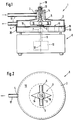
- a laboratory pump for liquids has a pump housing 2 with an inlet opening 3 and an outlet opening 4, in which a pump rotor 5 rotates.
- the pump rotor 5 has a magnet 6 which is magnetically coupled to a drive magnet 7 of a magnetic stirrer 8.
- the drive magnet 7 is arranged on the free end of a drive shaft 9 of a drive motor 10 of the magnetic stirrer 8 and rotates adjacent to a mounting surface 11 of the magnetic stirrer 8 about the longitudinal axis 12 of the drive shaft 9 oriented perpendicular to the mounting surface 11.
- the drive magnet 7 is centered on the drive shaft 9 arranged and aligned with its longitudinal axis perpendicular to its longitudinal axis 12.
- the free ends of the drive magnet 7 forming the magnetic poles thereby rotate on a circular path parallel to the mounting surface 11.
- the resulting rotating magnetic field is coupled to the magnetic field of the magnet 6, which is also adjacent and has its longitudinal axis parallel to the mounting surface 11, so that the magnet 6 and the pump rotor 5 connected to it rotate with the drive magnet 7.
- the laboratory pump 1 therefore does not have its own drive, but is driven by a magnetic stirrer 8.
- Magnetic stirrers present in laboratories can thus also be used as laboratory pump 1 with a very simply constructed additional part and thus have an additional function.
- the magnetic coupling between the pump rotor 5 and the magnetic stirrer 8 enables a particularly simple pump housing 2, in which a bushing for a drive shaft of the pump rotor is implemented 5 can be omitted.
- the pump rotor 5 is rotatably mounted on its upper side with a shaft 13 in a bearing bush 14 of the pump housing 2 and is supported on the lower housing wall 15 on its underside.
- the longitudinal axes of the shaft 13 of the pump rotor 5 and the drive shaft 9 are in the functional position on a common axis.
- the pump rotor 5 is designed as a vane pump wheel which sucks in the liquid to be pumped in the center and accelerates it radially outwards with the aid of the pump vanes 16.
- the inlet opening 3 of the pump housing 2 is therefore arranged above the core region of the pump rotor 5, while the outlet opening 4 is provided on the circumference of the pump housing 2.
- Inlet opening 3 and outlet opening 4 each have connecting pieces 17, on which, for example, a hose can be attached or pushed on.
- the pump blades 16 of the pump rotor 5 shown in FIGS. 1 and 2 are symmetrical and are aligned with their longitudinal center axis radially to the axis of rotation 18 of the pump rotor 5.
- the delivery rate of the pump 1 is therefore independent of the direction of rotation of the pump rotor 5, so that it can be used in the same way with magnetic stirrers 8 with a clockwise or with a counterclockwise drive magnetic field. This is particularly advantageous in the case of magnetic stirrers 8 with a switchable direction of rotation, since the pump 1 is then effective regardless of the respectively set direction of rotation.
- the magnet 6 is arranged perpendicular to the two pump blades 16 on a diameter of the pump rotor 5, so that there are practically four pump blades, two of which are formed by the magnet 6 itself.
- the space 6 to be kept free for the pump rotor 5 in the pump housing 2 is reduced by the magnet 6 arranged in the rotating area of the pump blades 16.
- the magnetic stirrer 8 has a heating plate 19 which, in the functional position, touches the lower housing wall 15 of the pump housing 2 and is thus coupled to the latter in a thermally conductive manner.
- the heating plate 19 can therefore be used for heating the liquid conveyed by the pump 1, which is why the pump 1 according to the invention is particularly well suited for heating the bath liquid and thermostatically controlled, preferably double-walled vessels.
- the drive of the magnetic stirrer 8 but also its heating plate 19 can be used for circulating and tempering the bath liquid.
- the pump housing 2 can be plugged onto the heating plate 19 of the magnetic stirrer 8 with a peripheral circumferential coupling edge 20, whereby the pump housing 2 is positively connected to the magnetic stirrer 8 at least in the direction of extension of the heating plate 19.
- the longitudinal axis 12 of the drive shaft 9 and the axis of rotation 18 of the pump rotor 5 are thus centered on one another in the functional position.
- the peripheral coupling edge 20 also enables a particularly good thermal coupling between the heating plate 19 and the pump housing 2, since the entire heat transfer surface of the heating plate 19 can be used for heat transfer. So that the pump housing 2 can also be used together with magnetic stirrers 8, the heating plate 19 of which has a larger outer diameter than the inner diameter of the coupling edge 20, the coupling edge 20 can be detachably connected to the pump housing 2.
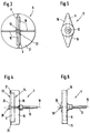
- FIGS. 3 and 4 show an exemplary embodiment of a pump rotor 5 with four pump blades 16, which are formed by thin platelets which are aligned radially to the axis of rotation 18 of the pump rotor 5 and are arranged on a common carrier disk 21.
- the carrier disk 21 is connected in one piece to the pump vanes 16 and therefore, despite the thin-walled, streamlined pump vanes 16, enables a pump rotor 5 of stable construction.
- the pump rotor 5 formed from the carrier disk 21 and the pump vanes 16 The unit is also designed as a holder for the magnet 6.
- the carrier disk 21 has on the flat side a rectangular recess 22 arranged symmetrically with respect to its axis of rotation 18, into which the magnet 6 with a longitudinal wall 23 is inserted flush with the underside of the carrier disk 21.
- the rectangular recess 22 is arranged centrally below two pump vanes 16 offset by 180 °, in which a recess 24 is also provided for the magnet 6.
- the magnet 6 thus engages both in the two pump blades 16 and in the carrier disk 21.
- a retaining screw 25 inserted into the shaft 13 is provided, the screw head of which forms the bearing surface 26 for the lower support bearing of the pump rotor 5.
- FIGS. 5 and 6 show a further embodiment of a pump rotor 5, which has two plastic pump blades 16 arranged on one of its diameters on both sides of its axis of rotation 18, into which the magnet 6 is cast. This results in a particularly compact pump rotor 5, in which the magnet 6 is particularly well protected against corrosion.
- the exemplary embodiment according to FIGS. 3 and 4 enables a particularly good magnetic coupling between the magnet 6 and the magnetic field of the magnetic stirrer 8, since the magnet 6 is arranged directly on the underside of the carrier disk 21 and therefore as close as possible to the installation surface 11 of the magnetic stirrer 8.
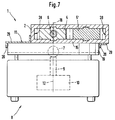
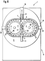
- the exemplary embodiment according to FIGS. 7 and 8 shows a laboratory pump 1 which has two intermeshing pump rotors 5, 5 'designed as spur gearwheels.
- a magnet 6 is integrated in the center of the pump rotor 5, the longitudinal axis of which is arranged perpendicular to the axis of rotation 18 of the pump rotor 5.
- the delivery medium entering through the inlet opening 3 is detected by the delivery teeth 27 moving closely along the inner side of the pump chamber 28 and in Displaced towards the outlet opening 4.
- comparatively high delivery pressures can be achieved.
- the delivery direction of the pump 1 can also be switched over from forward to backward delivery. It is also advantageous that the connections for the inlet opening 3 and the outlet opening 4 are arranged laterally on the pump housing 2, so that the upper side of the pump housing 2 can be designed as a flat surface which can be used, for example, as a storage surface.
- the magnet 6 integrated in the pump rotor 5 also enables a particularly compact and flat pump housing 2.
- the pump housing 2 also has three holding arms 29 arranged radially to the axis of rotation of the magnet 6, each offset by 90 ° to each other, which in the use position engage behind the heating plate 19 laterally, so that the axis of the magnet 6 coaxial with the axis of the drive magnet 7 of the magnetic stirrer 8 is arranged.
- the magnet 6 passes through a shaft 30 which carries a pinion 31, the toothing of which engages with the outer toothing of an intermediate pinion 32 which is connected in a rotationally fixed manner to the drive shaft 33 of the pump rotor 5.
- the magnet is arranged centrally below the pinion 31 and with its longitudinal axis perpendicular to its axis of rotation.
- the pinion 31 has a significantly smaller diameter than the intermediate pinion 32, so that overall there is a reduction gear which reduces the speed of the magnet 6 to a lower speed of the pump rotors 5, 5 '.
- the pinion 31 and the intermediate pinion 32 are arranged in an area of the pump housing 2 which is separated from the pump chamber 34 and sealed against it.
- the pump 1 is therefore particularly suitable for pumping viscous media, since the pumped medium does not come into contact with the pinions 31, 32 or the magnet 6 and therefore cannot cause any friction on these parts.
- the laboratory pump 1 for liquids has a pump housing 2 with an inlet opening 3 and an outlet opening 4, in which at least one pump rotor 5 rotates.
- the pump rotor 5 is connected to a magnet 6 directly or indirectly via a gear which is magnetically coupled to a rotating magnetic field of a magnetic stirrer 8.
- the pump housing 2 of the pump 1 can be connected to the magnetic stirrer 8 in such a way that the magnet 6 comes into the area of influence of the rotating magnetic field of the magnetic stirrer 8 and is driven by it.
- the pump according to the invention does not have its own drive and is therefore of particularly simple construction. Magnetic stirrers 8 present in laboratories can be used to drive the pump 1 and thus have an additional function.
Landscapes
- Engineering & Computer Science (AREA)
- Mechanical Engineering (AREA)
- General Engineering & Computer Science (AREA)
- Mixers With Rotating Receptacles And Mixers With Vibration Mechanisms (AREA)
- Details And Applications Of Rotary Liquid Pumps (AREA)
- Structures Of Non-Positive Displacement Pumps (AREA)
Applications Claiming Priority (2)
| Application Number | Priority Date | Filing Date | Title |
|---|---|---|---|
| DE4421431 | 1994-06-18 | ||
| DE4421431A DE4421431C2 (de) | 1994-06-18 | 1994-06-18 | Labor-Pumpe für Flüssigkeiten |
Publications (2)
| Publication Number | Publication Date |
|---|---|
| EP0692632A2 true EP0692632A2 (fr) | 1996-01-17 |
| EP0692632A3 EP0692632A3 (fr) | 1996-12-04 |
Family
ID=6520974
Family Applications (1)
| Application Number | Title | Priority Date | Filing Date |
|---|---|---|---|
| EP95104900A Ceased EP0692632A3 (fr) | 1994-06-18 | 1995-04-01 | Pompe à entraînement magnétique |
Country Status (4)
| Country | Link |
|---|---|
| US (1) | US5692885A (fr) |
| EP (1) | EP0692632A3 (fr) |
| JP (1) | JPH084664A (fr) |
| DE (1) | DE4421431C2 (fr) |
Families Citing this family (21)
| Publication number | Priority date | Publication date | Assignee | Title |
|---|---|---|---|---|
| DE29701888U1 (de) * | 1997-02-04 | 1997-03-27 | Wolters, Ralf, Dipl.-Ing., 44866 Bochum | Sterilisierbare, platzsparende Laborpumpe mit Rührkern als Rotor |
| WO1999018399A1 (fr) | 1997-10-06 | 1999-04-15 | Matsushita Refrigeration Company | Collecteur comportant un module thermoelectrique et un dispositif de refroidissement utilisant ce module |
| DE19858137B4 (de) * | 1998-12-16 | 2016-12-15 | BSH Hausgeräte GmbH | Heizung zum Erwärmen der Spülflüssigkeit in einer Geschirrspülmaschine |
| US7313840B2 (en) * | 2002-07-25 | 2008-01-01 | Charles E. Watkins | Induction liquid pump and magnetic tank scrubber |
| US7249571B2 (en) * | 2003-10-09 | 2007-07-31 | Mag-Life Llc | Aquarium having improved filtration system |
| US8513848B2 (en) | 2003-10-09 | 2013-08-20 | Mag Life, Llc | Aquarium having improved filtration system with neutral buoyancy substrate, pump and sediment removal system |
| TW200719126A (en) * | 2005-11-01 | 2007-05-16 | Sunonwealth Electr Mach Ind Co | Compact fluid pump |
| JP2009299471A (ja) * | 2008-04-24 | 2009-12-24 | Daito Kogyo Kk | マグネットカップリング機構を有するギアポンプ |
| US20080273999A1 (en) * | 2007-05-02 | 2008-11-06 | John David Jude | Machine for compressing gasses and refrigerant vapors |
| TW200920475A (en) * | 2007-11-02 | 2009-05-16 | Plus Lab Technology Co Ltd A | Electromagnetic stirring device |
| DE102009011987A1 (de) | 2009-03-05 | 2010-09-16 | RATIONAL Technische Lösungen GmbH | Mischgerät für den Laborbetrieb |
| US9693672B2 (en) | 2011-09-22 | 2017-07-04 | Whirlpool Corporation | Dishwasher with sprayer |
| JP5887822B2 (ja) * | 2011-10-18 | 2016-03-16 | セイコーエプソン株式会社 | 液体供給装置及び液体噴射装置 |
| US9532701B2 (en) | 2013-03-01 | 2017-01-03 | Whirlpool Corporation | Dishwasher with sprayer |
| US9713413B2 (en) | 2013-07-01 | 2017-07-25 | Whirlpool Corporation | Dishwasher for treating dishes |
| US9297553B2 (en) * | 2013-07-01 | 2016-03-29 | Whirlpool Corporation | Pump assembly |
| US9532699B2 (en) | 2013-07-15 | 2017-01-03 | Whirlpool Corporation | Dishwasher with sprayer |
| TWM517017U (zh) * | 2015-11-25 | 2016-02-11 | 百城機械企業有限公司 | 攪料送餡結構 |
| WO2019018704A1 (fr) | 2017-07-19 | 2019-01-24 | Group B Labs Llc | Préparation et conservation d'aliment liquide |
| US11219099B2 (en) * | 2018-07-19 | 2022-01-04 | Group B Labs, Inc. | Multiple pillar liquid heater |
| US11785674B2 (en) * | 2017-07-19 | 2023-10-10 | Group B Labs, Inc. | Multiple pillar liquid heater |
Family Cites Families (22)
| Publication number | Priority date | Publication date | Assignee | Title |
|---|---|---|---|---|
| DE753585C (de) * | 1941-01-12 | 1953-05-04 | Ig Farbenindustrie Ag | Heizbare Zahnradpumpe |
| US3139832A (en) * | 1963-07-24 | 1964-07-07 | Alan P Saunders | Centrifugal enclosed inert pump |
| FR1540100A (fr) * | 1966-10-04 | 1968-09-20 | Itt | Pompe à couplage magnétique |
| US3485177A (en) * | 1968-04-30 | 1969-12-23 | Atomic Energy Commission | Centrifugal pump having a shaftless impeller |
| US3493036A (en) * | 1968-06-28 | 1970-02-03 | Du Pont | Gear pump and heating and cooling means therefor |
| US3771906A (en) * | 1972-06-05 | 1973-11-13 | Robbins & Myers | Temperature control of stator/rotor fit in helical gear pumps |
| US3986797A (en) * | 1974-05-20 | 1976-10-19 | David Kopf Systems | Magnetic pump |
| US4266914A (en) * | 1979-03-12 | 1981-05-12 | Dickinson David G | Magnetic drive laboratory pump |
| CA1125712A (fr) * | 1979-04-16 | 1982-06-15 | Walter H. Cobbs, Jr. | Methode et appareil pour debiter des compositions polymerique liquides, sensibles a la chaleur |
| US4304532A (en) * | 1979-12-17 | 1981-12-08 | Mccoy Lee A | Pump having magnetic drive |
| DD213024B1 (de) * | 1982-12-31 | 1992-08-20 | Werner Eisenreich | Zahnradpumpe |
| US4846641A (en) * | 1983-08-08 | 1989-07-11 | Micropump Corporation | Readily-removable floating bushing pump construction |
| CH668919A5 (de) * | 1984-05-07 | 1989-02-15 | Dieter Alex Rufer | Geraet zum ruehren oder pumpen eines mediums. |
| US4643641A (en) * | 1984-09-10 | 1987-02-17 | Mici Limited Partnership Iv | Method and apparatus for sterilization of a centrifugal pump |
| US4927337A (en) * | 1986-09-08 | 1990-05-22 | Ferdinand Lustwerk | Magnetically driven pump |
| US4747744A (en) * | 1987-01-09 | 1988-05-31 | Eastman Kodak Company | Magnetic drive gerotor pump |
| JPH0799145B2 (ja) * | 1988-03-24 | 1995-10-25 | 日本碍子株式会社 | ルーツ形ポンプ用ヒステリシスマグネットカップリング |
| DE3927391A1 (de) * | 1989-08-19 | 1991-02-21 | Bosch Gmbh Robert | Vorrichtung zum beheizen des fahrgastraumes eines kraftfahrzeuges |
| DE4305023C2 (de) * | 1992-02-18 | 1999-08-19 | Oken Seiko Kk | Flügelradpumpe |
| DE4303629A1 (de) * | 1993-02-09 | 1994-08-18 | Junkalor Gmbh | Übertemperatur- und Anlaufsicherung in Pumpen mit Permanentmagnet-Kupplungen |
| US5525039A (en) * | 1993-07-21 | 1996-06-11 | Roy E. Roth Company | Hermetically sealed magnetic drive pump |
| DE9400471U1 (de) * | 1994-01-13 | 1994-04-21 | Janke & Kunkel GmbH & Co. KG IKA-Labortechnik, 79219 Staufen | Magnetrührer mit einer heizbaren Aufstellplatte |
-
1994
- 1994-06-18 DE DE4421431A patent/DE4421431C2/de not_active Expired - Fee Related
-
1995
- 1995-04-01 EP EP95104900A patent/EP0692632A3/fr not_active Ceased
- 1995-06-14 JP JP7147878A patent/JPH084664A/ja active Pending
- 1995-06-14 US US08/490,220 patent/US5692885A/en not_active Expired - Fee Related
Also Published As
| Publication number | Publication date |
|---|---|
| DE4421431A1 (de) | 1995-12-21 |
| DE4421431C2 (de) | 1997-07-17 |
| EP0692632A3 (fr) | 1996-12-04 |
| JPH084664A (ja) | 1996-01-09 |
| US5692885A (en) | 1997-12-02 |
Similar Documents
| Publication | Publication Date | Title |
|---|---|---|
| DE4421431C2 (de) | Labor-Pumpe für Flüssigkeiten | |
| CH668101A5 (de) | Magnetisch angetriebene zentrifugalpumpe. | |
| DE69606293T2 (de) | Niedrigdurchflusspumpe | |
| DE1450113B2 (de) | Flüssigkeitsreibungskupplung | |
| DE2532262A1 (de) | Magnetisch angetriebene kreiselpumpe | |
| DE2750801C2 (de) | Pumpe, insbesondere Faßpumpe | |
| DE2246265A1 (de) | Pumpe mit taumelbarem laeufer | |
| EP0112462B1 (fr) | Pompe centrifuge autonettoyante | |
| DE2205959A1 (de) | Pump- und Filtereinheit | |
| DE4433907A1 (de) | Rotationsrührwerk mit konzentrisch angeordnetem Saugrohr | |
| DE1553183B2 (de) | Schraubenrohrpumpe | |
| WO2006027043A1 (fr) | Dispositif de circulation de fluides | |
| DE3640657A1 (de) | Pumpe fuer fluessige medien | |
| DE2626449C3 (de) | Führungsgetriebe für eine parallel- und innenachsige Umlaufkolbenmaschine | |
| DE9409901U1 (de) | Labor-Pumpe für Flüssigkeiten | |
| EP0689865B1 (fr) | Tête de mélange dynamique | |
| DE4305023A1 (fr) | ||
| DE202005013923U1 (de) | Anordnung zur Förderung von Fluiden | |
| DE2754621B1 (de) | Vorrichtung zur Belueftung von Fluessigkeiten auf Wasserbasis,insbesondere Guelle oder Kanalabwaesser | |
| DE10312978A1 (de) | Elektrohydrodynamisches Aggregat | |
| DE4205542A1 (de) | Selbstansaugende seitenkanalpumpe | |
| DE1653670A1 (de) | Radialpumpe mit selbsteinstellendem hydraulischem Kraefteausgleich | |
| DE2844990C2 (de) | Kreiselpumpe | |
| DE2455321C2 (de) | Behälterpumpe | |
| DE1450113C (de) | Flüssigkeitsreibungskupplung |
Legal Events
| Date | Code | Title | Description |
|---|---|---|---|
| PUAI | Public reference made under article 153(3) epc to a published international application that has entered the european phase |
Free format text: ORIGINAL CODE: 0009012 |
|
| AK | Designated contracting states |
Kind code of ref document: A2 Designated state(s): CH DE FR GB IT LI |
|
| 17P | Request for examination filed |
Effective date: 19960710 |
|
| PUAL | Search report despatched |
Free format text: ORIGINAL CODE: 0009013 |
|
| AK | Designated contracting states |
Kind code of ref document: A3 Designated state(s): CH DE FR GB IT LI |
|
| GRAG | Despatch of communication of intention to grant |
Free format text: ORIGINAL CODE: EPIDOS AGRA |
|
| 17Q | First examination report despatched |
Effective date: 19990811 |
|
| STAA | Information on the status of an ep patent application or granted ep patent |
Free format text: STATUS: THE APPLICATION HAS BEEN REFUSED |
|
| 18R | Application refused |
Effective date: 20000205 |