EP0692704A1 - Assemblage de transducteur de température - Google Patents
Assemblage de transducteur de température Download PDFInfo
- Publication number
- EP0692704A1 EP0692704A1 EP95110824A EP95110824A EP0692704A1 EP 0692704 A1 EP0692704 A1 EP 0692704A1 EP 95110824 A EP95110824 A EP 95110824A EP 95110824 A EP95110824 A EP 95110824A EP 0692704 A1 EP0692704 A1 EP 0692704A1
- Authority
- EP
- European Patent Office
- Prior art keywords
- heat
- assembly
- wall section
- housing
- signal producing
- Prior art date
- Legal status (The legal status is an assumption and is not a legal conclusion. Google has not performed a legal analysis and makes no representation as to the accuracy of the status listed.)
- Withdrawn
Links
- 238000012546 transfer Methods 0.000 claims abstract description 46
- 239000004020 conductor Substances 0.000 claims description 24
- 239000000463 material Substances 0.000 claims description 20
- 238000004873 anchoring Methods 0.000 claims description 15
- 239000011810 insulating material Substances 0.000 claims description 8
- 239000004033 plastic Substances 0.000 claims description 4
- 230000000903 blocking effect Effects 0.000 claims description 2
- 239000002991 molded plastic Substances 0.000 claims description 2
- 239000000126 substance Substances 0.000 claims 1
- 239000003570 air Substances 0.000 description 32
- 239000012080 ambient air Substances 0.000 description 14
- 239000003507 refrigerant Substances 0.000 description 9
- 239000012212 insulator Substances 0.000 description 8
- 238000009434 installation Methods 0.000 description 6
- 239000002184 metal Substances 0.000 description 4
- 229910052751 metal Inorganic materials 0.000 description 4
- 238000000034 method Methods 0.000 description 4
- 238000013459 approach Methods 0.000 description 3
- 238000010276 construction Methods 0.000 description 3
- 238000010438 heat treatment Methods 0.000 description 3
- 238000012544 monitoring process Methods 0.000 description 3
- 238000010257 thawing Methods 0.000 description 3
- 230000006978 adaptation Effects 0.000 description 2
- 230000002411 adverse Effects 0.000 description 2
- 230000000712 assembly Effects 0.000 description 2
- 238000000429 assembly Methods 0.000 description 2
- 238000001816 cooling Methods 0.000 description 2
- 230000008878 coupling Effects 0.000 description 2
- 238000010168 coupling process Methods 0.000 description 2
- 238000005859 coupling reaction Methods 0.000 description 2
- 230000000694 effects Effects 0.000 description 2
- 239000012530 fluid Substances 0.000 description 2
- 230000007246 mechanism Effects 0.000 description 2
- 238000012986 modification Methods 0.000 description 2
- 230000004048 modification Effects 0.000 description 2
- 239000000615 nonconductor Substances 0.000 description 2
- 238000004382 potting Methods 0.000 description 2
- 238000005057 refrigeration Methods 0.000 description 2
- 239000002470 thermal conductor Substances 0.000 description 2
- OKTJSMMVPCPJKN-UHFFFAOYSA-N Carbon Chemical compound [C] OKTJSMMVPCPJKN-UHFFFAOYSA-N 0.000 description 1
- RYGMFSIKBFXOCR-UHFFFAOYSA-N Copper Chemical compound [Cu] RYGMFSIKBFXOCR-UHFFFAOYSA-N 0.000 description 1
- -1 Copper C17200 Chemical compound 0.000 description 1
- 229910000881 Cu alloy Inorganic materials 0.000 description 1
- 239000004593 Epoxy Substances 0.000 description 1
- 229920004142 LEXAN™ Polymers 0.000 description 1
- 239000004418 Lexan Substances 0.000 description 1
- 239000004677 Nylon Substances 0.000 description 1
- 230000035508 accumulation Effects 0.000 description 1
- 238000009825 accumulation Methods 0.000 description 1
- 230000001154 acute effect Effects 0.000 description 1
- 239000002131 composite material Substances 0.000 description 1
- 229910052802 copper Inorganic materials 0.000 description 1
- 239000010949 copper Substances 0.000 description 1
- 230000007423 decrease Effects 0.000 description 1
- 230000003467 diminishing effect Effects 0.000 description 1
- 238000010292 electrical insulation Methods 0.000 description 1
- 238000007710 freezing Methods 0.000 description 1
- 230000008014 freezing Effects 0.000 description 1
- 239000011521 glass Substances 0.000 description 1
- 229910002804 graphite Inorganic materials 0.000 description 1
- 239000010439 graphite Substances 0.000 description 1
- 238000011065 in-situ storage Methods 0.000 description 1
- 238000002347 injection Methods 0.000 description 1
- 239000007924 injection Substances 0.000 description 1
- 238000009413 insulation Methods 0.000 description 1
- 230000003993 interaction Effects 0.000 description 1
- 239000007788 liquid Substances 0.000 description 1
- 229920001778 nylon Polymers 0.000 description 1
- 230000002093 peripheral effect Effects 0.000 description 1
- 239000004417 polycarbonate Substances 0.000 description 1
- 229920000515 polycarbonate Polymers 0.000 description 1
- 230000004043 responsiveness Effects 0.000 description 1
- 238000007789 sealing Methods 0.000 description 1
- 238000000926 separation method Methods 0.000 description 1
- 230000011664 signaling Effects 0.000 description 1
- 230000007480 spreading Effects 0.000 description 1
- 239000012815 thermoplastic material Substances 0.000 description 1
Images


Classifications
-
- G—PHYSICS
- G01—MEASURING; TESTING
- G01K—MEASURING TEMPERATURE; MEASURING QUANTITY OF HEAT; THERMALLY-SENSITIVE ELEMENTS NOT OTHERWISE PROVIDED FOR
- G01K1/00—Details of thermometers not specially adapted for particular types of thermometer
- G01K1/14—Supports; Fastening devices; Arrangements for mounting thermometers in particular locations
- G01K1/143—Supports; Fastening devices; Arrangements for mounting thermometers in particular locations for measuring surface temperatures
-
- G—PHYSICS
- G01—MEASURING; TESTING
- G01K—MEASURING TEMPERATURE; MEASURING QUANTITY OF HEAT; THERMALLY-SENSITIVE ELEMENTS NOT OTHERWISE PROVIDED FOR
- G01K1/00—Details of thermometers not specially adapted for particular types of thermometer
- G01K1/16—Special arrangements for conducting heat from the object to the sensitive element
-
- G—PHYSICS
- G01—MEASURING; TESTING
- G01K—MEASURING TEMPERATURE; MEASURING QUANTITY OF HEAT; THERMALLY-SENSITIVE ELEMENTS NOT OTHERWISE PROVIDED FOR
- G01K1/00—Details of thermometers not specially adapted for particular types of thermometer
- G01K1/20—Compensating for effects of temperature changes other than those to be measured, e.g. changes in ambient temperature
-
- Y—GENERAL TAGGING OF NEW TECHNOLOGICAL DEVELOPMENTS; GENERAL TAGGING OF CROSS-SECTIONAL TECHNOLOGIES SPANNING OVER SEVERAL SECTIONS OF THE IPC; TECHNICAL SUBJECTS COVERED BY FORMER USPC CROSS-REFERENCE ART COLLECTIONS [XRACs] AND DIGESTS
- Y10—TECHNICAL SUBJECTS COVERED BY FORMER USPC
- Y10S—TECHNICAL SUBJECTS COVERED BY FORMER USPC CROSS-REFERENCE ART COLLECTIONS [XRACs] AND DIGESTS
- Y10S236/00—Automatic temperature and humidity regulation
- Y10S236/06—Clamp on
Definitions
- the present invention relates to a temperature sensing assembly and more particularly to a temperature sensing assembly for monitoring the temperature of an object in an ambient fluid having a temperature which is different from that of the object.
- Temperature sensing assemblies for monitoring the temperature of an object in an ambient fluid having a different temperature are used in many different applications.
- An example is a "heat pump" refrigeration system used for heating and cooling buildings.
- refrigerant is passed through an outdoor heat exchanger where it is evaporated and gathers heat from outdoor air.
- the refrigerant is then compressed and passed through an indoor heat exchanger where the heat is transferred from the refrigerant to indoor air for heating the building.
- the outdoor heat exchanger typically includes a highly conductive metal flow tube through which the refrigerant flows for efficient heat exchange between the tube and its environment (usually atmospheric air). Atmospheric air is blown across the heat exchanger to maximize convective heat transfer between the flow tube and the air.
- frost or ice may form on the outdoor heat exchanger flow tubes. The ice or frost insulates the tubes.
- the impeded heat transfer reduces the heat pump efficiency and requires periodically clearing frost or ice from the outdoor heat exchanger flow tubes.
- So called "demand defrost" heat pump systems are designed to defrost the outdoor heat exchanger flow tubes when ice or frost has actually formed.
- Numerous different approaches to sensing frost or ice accumulations have been proposed.
- One general approach is to sense the temperature difference between the atmospheric air and the outdoor flow tubes when the atmospheric air temperature approaches freezing.
- the insulating effect of frost on the flow tube reduces heat flow to the refrigerant from the ambient air. Consequently, when ice or frost forms the outdoor heat exchanger, flow tube surface temperature drops relative to the ambient air temperature.
- the existence of a predetermined temperature differential between the flow tube surface and ambient air signifies that frost or ice is present and the tube should be defrosted.
- Modern demand defrost systems are typically electrically operated and rely on temperature sensors which produce electric signals having values dependant upon sensed flow tube temperature. It is essential that the sensing elements be electrically isolated from the flow tubes. Typical electrical insulators are also effective heat insulators. Electrically isolating the sensors from the flow tubes thus has the effect of diminishing heat transfer between sensor and flow tube. This has reduced defrost system responsiveness.
- Temperature sensor devices have been attached to the outdoor tubes in different ways.
- One technique was to clamp an electrically insulated temperature sensor device directly onto the tube using a hose clamp or spring clip. This assured good thermal contact between the heat exchanger flow tube and the temperature sensor, but placed the sensor in convective heat transfer relationship with the atmospheric air. Inaccurate flow tube temperature readings resulted.
- heavy insulating tape was sometimes wrapped around the sensor and flow tube. The tape tended to assume the ambient air temperature and adversely influence the sensor output signal.
- sensors were placed in metal housings clamped to the flow tubes.
- the housing materials were efficient heat conductors but the sensors had to be electrically insulated from the flow tubes.
- the sensors were thus stationed in the housings in a body of plastic or other electric insulating material.
- the electrical insulating materials were likewise thermal insulators. These devices did not produce acceptably accurate flow tube temperature readings.
- the sensors In order to function as required for a demand defrost application the sensors had to be constructed so that they quickly and accurately monitored the flow tube temperature. This required efficient thermal coupling between the sensor and the flow tube. At the same time the sensors had to be unresponsive to ambient air temperature, an attribute of a good heat insulator. Finally, the sensors had to be mounted so that they were electrically insulated and isolated from the heat pump system components. These conflicting requirements were not satisfied in prior art sensor constructions.
- the present invention provides a new and improved temperature sensing assembly for sensing the temperature of an object in a fluent medium and producing an electrical output signal, the assembly being so constructed and arranged that the sensor is electrically isolated from the object, effectively thermally coupled to the object and insulated from heat exchange with the fluent medium.
- a heat transfer structure is disposed in heat transfer relationship between the housing and the object and tends to maintain the object and the housing temperatures the same.
- the heat transfer structure is disposed at least partly in the channel between the housing and the insulating jacket so that the insulating jacket resists heat transfer between the ambient fluent medium and the heat transfer structure.
- the preferred and illustrated heat transfer structure comprises a heat conductive spring member which also serves to secure the sensor assembly in heat transfer relationship with the object.
- the preferred sensor assemblies employ an anchoring arrangement for securing the signal producing element in heat transfer relationship with the heat transmitting housing wall wherein a positioner member latches into position for maintaining the signal producing element in heat transfer relationship with the heat transmitting wall.
- FIG. 1 schematically depicts an outdoor heat exchanger installation 10 forming part of a heat pump system for heating and cooling a building.
- the heat exchanger installation 10 absorbs heat from atmospheric air and delivers the heat to the building interior.
- the installation delivers heat from inside the building to the atmospheric air.
- the installation 10 comprises a heat exchanger 11, a housing, or enclosure, 12 surrounding and supporting the heat exchanger 11, and a blower (not illustrated) supported by the housing for forcing atmospheric air flows across the heat exchanger.
- the heat exchanger 11 comprises a long refrigerant flow tube 18 which is wound back and forth within the housing. Closely spaced, thermally conductive metal fins (not illustrated) are assembled to the tube to increase the effectiveness of the convective heat transfer between the tube and the atmospheric air.
- the blower is located in the top center of the housing and forces atmospheric air through the fins and across the flow tube 18 via appropriate vent openings in the housing walls.
- the heat exchanger, blower and housing may be of any conventional or suitable construction and therefore are not described in detail.
- the heat pump system operates to heat the building.
- the installation 10 absorbs heat from the atmospheric air and delivers the heat to the building interior.
- the temperature differential between the flow tube 18 and the air may be relatively small. In such conditions ice or frost readily forms on the heat exchanger surfaces. This materially reduces the efficiency of the heat exchanger and requires prompt defrosting.
- Defrosting the heat exchanger 11 is preferably controlled in the manner disclosed by U.S. Patent No. 4,882,908 to White entitled “Demand Defrost Control Method and Apparatus," the disclosure of which is hereby incorporated herein in its entirety by this reference.
- the control module 20 is associated with a temperature sensing assembly 22 mounted on the flow tube 18 for signalling the flow tube temperature via a signal cable 24.
- An atmospheric air temperature sensor not illustrated, enables monitoring the differential between the flow tube temperature and the atmospheric air temperature.
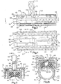
- the temperature sensing assembly 22 comprises a housing 30, a thermally responsive signal producing assembly 34 supported in the housing 30, and mounting structure 38 for connecting the assembly 22 to the flow tube 18.
- the illustrated housing 30 comprises an anchoring arrangement 36 for positioning and securing the signal producing assembly in place in the housing.
- the temperature sensing assembly 22 is mounted at a flow tube location which is best determined according to the geometry of the heat exchanger and enclosure as well as the operating characteristics of the blower.
- the housing 30 is formed from electrical insulating materials which are relatively poor thermal conductors and comprises a thin walled heat transmitting wall section 40 extending substantially the entire length of the housing, a relatively thick, heat insulating structural support wall section 42 coextending with the wall section 40 and a relatively thick, heat insulating end wall 44.
- the illustrated housing wall sections 40, 42, and 44 define the walls of a chamber 32 and are formed by a single continuous body of molded polycarbonate thermoplastic material such as G.E. Lexan 500r-7344@ or another suitable alternative.
- the wall section 40 defines a film (preferably 0.01 in. thick) extending continuously throughout the length of the chamber and shaped to conform to the peripheral flow tube surface.
- the illustrated film wall is thus concave and cylindrically curved to conform to the circular flow tube cross sectional shape. Even though the film wall material thermal conductivity is quite low, the large contact area between the flow tube surface and the wall section 40, together with the short conduction path through the wall, enables the wall section 40 to function as an efficient heat conductor.
- the housing wall section 42 comprises a base wall portion 50 and laterally spaced side wall portions 52 extending between the base wall portion edges and the film wall section edges.
- the housing wall section 42 is "U" shaped in cross section.
- the concavely curved film wall section medial portion 54 projects toward the base wall portion 50 between the side wall portions.
- the housing end wall section 44 is preferably thick and imperforate and closes the chamber end opposite to the open housing end.
- the signal producing assembly 34 comprises an electrical signal producing element 60 disposed in the chamber 32 in heat transfer relationship with the heat transmitting wall section 40 and first and second conductors 62, 64 extending into the chamber for completing an electric circuit through the element 60.
- the conductors 62, 64 form part of the signal cable 24 and are uninsulated in the vicinity of the element 60.
- Each conductor extends to the control module and is shrouded by a resilient plastic insulator 65.
- the insulators 65 extend slightly into the chamber 32.
- the preferred signal producing element 60 is a generally cylindrical thermistor with integral wire leads extending from opposite ends for connection to the conductors 62, 64 by suitable splices.
- the thermistor has a larger diameter (about 0.090 inches) than the leads and the conductors.
- the thermistor is hermetically sealed by a glass bead-like shield.
- the anchoring arrangement 36 locates and fixes the signal producing assembly in place in the chamber.
- the illustrated anchoring arrangement 36 comprises a septal rib 70 in the chamber 32 for locating the element 60 near the wall section 40 with the conductors 62, 64 separated, a positioner unit 72 securing the assembly in place in the housing 30, and a body 74 encapsulating the assembly 34 when it has been positioned in the chamber.
- the septal rib 70 engages and guides the signal producing assembly as it is inserted into the chamber so that the assembly assumes a desired position in the housing.
- the rib 70 extends longitudinally along the chamber base wall portion 50 and projects toward the wall section medial portion 54 for engagement with the signal producing assembly.
- the rib projects sufficiently far into the housing so the element 60 is maintained in position along one side wall portion 52 and the conductors and leads are effectively spaced from each other in the chamber to preclude short circuiting the thermistor.
- One of the leads forms a loop-like projecting end of the signal producing assembly 34 and is guided into close proximity with the wall section 40 by the rib. This interaction assures that the thermistor is likewise positioned in engagement with or immediately adjacent the wall section 40.
- the positioner unit 72 secures the signal producing assembly in place in the housing so that tensile forces tending to pull the housing 30 from the cable 24 are not exerted on the signal producing assembly.
- the unit 72 comprises a positioner member 76 for engaging and positioning the signal producing assembly and a latching mechanism for securing the positioner member in place.
- the preferred positioner member 76 has a shaped end projecting into the chamber between the conductors 62, 64 adjacent the open chamber end.
- the positioner member end comprises outwardly diverging wedging faces 78.
- the faces 78 wedge the conductors apart and into tight, frictional contact with the chamber side wall portions.
- the faces 78 engage the conductors where each is jacketed by an insulator. The insulators are compressed slightly against the chamber wall.
- the latching mechanism comprises latching elements formed by faces 80, 82, located respectively on the positioner member 76 and the housing 30, confronting each other when the member 76 wedges the conductors into place to prevent withdrawal of the member 76 from the housing.
- the member 76 carries a keeper face 80 at the wide end of each wedging face 78.
- Each keeper face 80 intersects its associated wedging face 78 at an acute angle with the face 80 extending from the wedging face end to the member 76.
- the latching faces 82 are formed on the base wall portion 50.
- a positioner member receiving slot 84 extends through the base wall portion 50 from the open chamber end toward the rib 70.
- the slot 84 extends longitudinally relative to the housing 30 along the base wall portion mid-line.
- the longitudinally extending slot sides 86 diverge from each other proceeding away from the chamber 32 at an included angle which is larger than the included angle of the wedging faces 78.
- the latching faces 82 extend along the edges of the slot 84 in the chamber.
- the positioner member 76 is inserted into the chamber by forcing the wedging faces 78 through the slot 84 with the wedging faces 78 passing between the slot sides 86.
- the housing wall portions defining the slot sides 86 and the associated latching faces 82 resiliently deflect away from each other as the wedging faces pass between them.
- the slot sides spring back to their initial positions so that the latching faces 82 confront the keeper faces 80.
- the positioner member end can not be withdrawn from the chamber.
- the positioner member 76 is a continuous integral part of the temperature sensing assembly 22.
- the illustrated positioner member is elongated and has a square or rectangular cross sectional shape.
- the width of the member 76, except for the wedging faces 78, is less than the width of the slot 84.
- the member 76 fits easily between the slot sides except when the slot sides are engaged by the wedging faces 78.
- the member 76 is connected to the housing at the closed end of the slot 84 by a thin flexible hinge strap 88.
- the member 76, housing 30 and the strap 88 are molded as a single continuous unit. The strap 88 flexes as the positioner end is aligned with and manually pushed through the slot 84 to its latched-in-place location.
- the body 74 engulfs, or encapsulates, the signal producing assembly 34 in the housing 30 to aid in fixing the assembly in place as well as to provide a heat transfer path between the film wall section 40 and the thermistor.
- the material forming the body 74 is an electrical insulator which is preferably a plastic or epoxy inserted into the chamber 32 in a liquid state before the positioner 76 is latched in place. In order to best assure the absence of air bubbles or other discontinuities in the body 74 the material is flowed into the chamber via a suitable cannula. When the chamber 32 is appropriately filled, the positioner 76 is latched in place and the body 74 is cured. In this preferred embodiment of the invention a potting material known as Conap DPEN 8536 is used to form the body 74.
- the positioner member 76 extends to a location immediately adjacent the wall section 40 when latched in place.
- the wedging faces 78 engage and deform the insulation around the conductors 62, 64 so that the end of the chamber 32 remote from the wall 44 is essentially closed. This prevents loss of liquified potting material from the chamber before the body 74 is cured. Squeezing and deforming the insulating material 65 as described also assures that the conductors are gripped extremely tightly.
- the mounting structure 38 not only retains the temperature sensing assembly 22 in place on the flow tube, but also forms a highly conductive heat flow path between the flow tube and the housing 30.
- the mounting structure heat flow path is shielded to minimize convective heat exchange with the ambient air stream.
- the preferred structure 38 comprises a resilient retainer member 90 secured to the housing 30 and to the flow tube 18, and an insulating jacket 92 for blocking heat transfer between the retainer member and ambient atmospheric air.
- the retainer member material is a copper (e.g. Copper C17200, 1/4 HT), or copper alloy, spring metal having a high thermal conductivity so that heat from both the ambient air and the housing 30 flows through it to the flow tube 18 when the heat pump is operating to heat the building.
- the retainer member 90 has a central body portion 93 attached to the housing 30 and projecting gripping fingers 94 resiliently engaging the flow tube 18.
- the body portion 93 tightly engages and conforms to the exterior of the heat insulating wall section 42.
- the large area conductive interface between the retainer member 90 and the wall section 42 assures maximal heat flow between them.
- the wall section temperature tends always to approximate the flow tube temperature because of the heat sink-like character of the retainer member.
- the fingers 94 project from the housing 30 to the flow tube 18 and define arcuate sections 96 contiguous with outwardly extending tab-like ends 98.
- the ends 98 guide the fingers onto the flow tube when the assembly 22 is initially mounted and facilitate spreading the fingers during assembly removal.
- the resilient arcuate sections 96 confront and closely conform to the flow tube periphery. This maximizes heat flow between the retainer member and the flow tube and minimizes chances for frost or ice buildups between them.
- the arcuate sections 96 additionally resiliently urge the flow tube into snug contact with the film wall 40.
- the insulating jacket 92 minimizes convective heat transfer between the ambient atmospheric air being blown across the heat exchanger 11, the retainer member 90 and housing section 42.
- the housing 30 is placketed to provide a retainer member receiving channel 100 between the wall section 42 and the surrounding jacket 92.
- the preferred jacket 92 is molded continuously with the housing 30 and projects from the end wall 44 parallel to the wall section 42.
- the jacket 92 is relatively thin walled and defines a base wall portion 102 and depending side wall portions 104 projecting from the portion 102 towards the flow tube 18.
- the base wall portion 102 is bifurcated to provide a positioner member accommodating slot 106.
- the positioner member 76 moves through the slot 106 as it is being latched into position while fabricating the assembly 22.
- the slot 106 is relatively narrow and oriented so that only relatively weak eddy currents of ambient air, if any at all may be established in the channel 100. These currents are insufficient to produce any significant convective heat transfer with the retainer member parts in the channel so the channel is, for all intents and purposes, a "dead" air space.
- the side wall portions 104 extend parallel to the retainer member fingers 94 and terminate adjacent the arcuate finger sections 96.
- the side wall portions 104 shield the retainer member fingers in the channel 100 from the ambient air.
- the side wall portions 104 block convective heat transfer between the ambient air and the retainer fingers remote from the flow tube 18.
- the retainer member fingers adjacent the flow tube are subject to convective heat transfer from ambient air blown across the heat exchanger.
- the retainer member conductivity is so great and the heat transfer coupling between the fingers 94 and the flow tube 18 is so efficient that the ambient air condition has minimal impact on the temperature of the housing 30.
- FIGS 7-10 illustrate another preferred temperature sensing assembly 122 embodying the invention mounted on a refrigerant flow tube 118.
- the temperature sensing assembly 122 comprises a housing 130, a thermally responsive signal producing assembly 134 supported in the housing 130, and mounting structure 138 for connecting the assembly 122 to the flow tube 118.
- the temperature sensing assembly 122 is mounted at a flow tube location which is best determined according to the geometry of the heat exchanger and enclosure as well as the operating characteristics of the blower.
- the signal producing assembly 134 is constructed like the assembly 34 described above in reference to Figures 1-6. Parts of the assembly 134 which are identical to parts of the assembly 34 are indicated by corresponding primed reference characters in Figures 7-9.
- the illustrated housing 130 comprises an anchoring arrangement formed by a core-like member 136 for positioning the signal producing assembly 134 in place in the housing 130 and a rigid body 139 of electrical insulating material molded over the core member and the signal producing assembly for encapsulating and securing the signal producing assembly in situ in the core member 136.
- the housing 130 is thus formed by a composite of the core member 136 and the body 139, both consisting of molded electrical insulating materials which are relatively poor thermal conductors.
- the core member 136 comprises a thin, heat transmitting wall section 140 extending substantially the entire length of the core member, relatively thicker, structural support wall sections 142 projecting from opposite lateral sides of, and coextending with, the wall section 140, a relatively thick, end wall 144 extending transversely with respect to the wall sections, and a septal rib 145 projecting from the center of the wall section 140 and extending parallel to the walls 142.
- the illustrated housing wall sections 140, 142, 144, and the septal rib 145 define a chamber 132 for receiving the signal producing assembly 134.
- the rib 145 terminates just short of the wall 144 to define a slot 146 through which a thermistor lead extends.
- the core member 136 is formed by a single continuous body of molded material which exhibits maximum heat transmissivity consonant with assuring that the signal producing assembly has adequate electrical insulation.
- the preferred core member is formed from 30% graphite filled 6/6 nylon.
- the wall section 140 is a film-like element (on the order of 0.01 inches thick) cylindrically curved to conform to the flow tube periphery. Heat conduction through the wall section 140 is facilitated by the very thin section. Heat flow between the flow tube and the thermistor through the wall section 140 is relatively efficient and the core element temperature closely follows the flow tube temperature via conduction through the core member material.
- the core member 136 is constructed and arranged so that anchoring structure maintains the thermistor in heat transfer contact with the wall section 140 and one of the wall sections 142.
- the wall sections 142 each terminate in a lip 142a projecting toward the septal rib.
- the clearance between the lip 142a and the rib 145 is smaller than the diameter of the thermistor.
- the wall section 142 and the rib 145 are resiliently deformed by the thermistor as it passes between them during assembly of the signal producing assembly to the core member 136.
- the wall sections 142 and the rib 145 snap back toward their normal positions after the thermistor passes between them so the thermistor is resiliently anchored between the wall sections 140, 142. This assures good heat transmitting contact between the thermistor and both wall sections.
- the core member 136 and signal producing assembly 134 are placed in a mold cavity (not illustrated) and material forming the body 139 is injected into the mold to substantially encapsulate both the core member and the assembly 134.
- the preferred core member 136 is positioned within the mold cavity by locating projections, generally indicated by the reference character 148, which respectively engage a cavity surface.
- the projections 148 engage the mold cavity to force the core member 136 to a position where the wall section 140 is firmly engaged with a conforming cylindrical mold cavity surface. Full surface engagement between the wall section 140 and the mold cavity assures that the material forming the body 139 does not cover the outer surface of the wall section 140.
- the body 139 comprises a housing section 150 surrounding and encapsulating the core member 136 (except for the exposed cylindrical face of the wall section 140) and the signal producing assembly 134, an end wall 152 adjacent and fixed to the core member end wall section 144, and a heat insulating jacket 192 projecting from the end wall 152 parallel to and spaced from the housing section 150.
- the body 139 is formed from an injection molded plastic electrical insulating material selected to exhibit a relatively low degree of thermal conductivity. Thus, compared to the core member material, the body 139 is a heat insulator.
- the housing section 150 defines walls 150a extending along the core member walls 142, a central section 150b between the walls 150a and an end segment 150d projecting a short distance from the core member end for hermetically sealing the conductors.
- the core member projections 148 further serve to lock the core member 136 and body 139 together when the body material solidifies.
- the locating projections 148a on the wall sections 142 take the form of longitudinally extending lands projecting laterally from the core member. Each projection 148a extends through a respective housing section wall 150a.
- the septal rib projection 148b is a longitudinally extending land projecting through the central section 150b.
- the material of the central section 150b flows around the septal rib into the core member chamber 132 completely filling the chamber and engulfing the signal producing assembly.
- the central section 150b forms part of the anchoring structure in that it secures the thermistor in place against the wall section 140 when it has solidified.
- a central section end 151 projects from the chamber end along the conductors to hermetically seal the entry location of the conductors into the chamber.
- the locating projections on the end wall section 144 are formed by a single cylindrical dowel-like longitudinal projection 148c and a pair of laterally extending tangs 148d.
- the projection 148c extends through the end wall 152 while the tangs 148d project through the jacket 192 at its juncture with the end wall 152.
- the jacket 192 and housing section 150 are spaced to define a channel 200 between them.
- the mounting structure 138 is disposed in the channel.
- the preferred mounting structure comprises a resilient retainer member 190 having a high heat conductivity and secured to the housing section 150 and to the flow tube 118.
- the insulating jacket 192 blocks convective heat transfer between the retainer member 190 and ambient atmospheric air.
- the channel 200 forms an insulating dead air space between the jacket 192 and both the retainer member 190 and the housing section 150.
- the jacket 192 has a very thin cross section which, together with its low thermal conductivity, minimizes heat flow along the jacket and thus minimizes heat transfer between the jacket and the housing 150 and its contents.
- the retainer member is constructed the same as the member 90 referred to above. Accordingly, the retainer member tends to maintain the temperature of the housing section 150 the same as the flow tube temperature. This further insures responsive, accurate temperature related signals from the thermistor.
Landscapes
- Physics & Mathematics (AREA)
- General Physics & Mathematics (AREA)
- Air Conditioning Control Device (AREA)
Applications Claiming Priority (2)
| Application Number | Priority Date | Filing Date | Title |
|---|---|---|---|
| US273588 | 1994-07-11 | ||
| US08/273,588 US5707151A (en) | 1994-01-13 | 1994-07-11 | Temperature transducer assembly |
Publications (1)
| Publication Number | Publication Date |
|---|---|
| EP0692704A1 true EP0692704A1 (fr) | 1996-01-17 |
Family
ID=23044576
Family Applications (1)
| Application Number | Title | Priority Date | Filing Date |
|---|---|---|---|
| EP95110824A Withdrawn EP0692704A1 (fr) | 1994-07-11 | 1995-07-11 | Assemblage de transducteur de température |
Country Status (2)
| Country | Link |
|---|---|
| US (1) | US5707151A (fr) |
| EP (1) | EP0692704A1 (fr) |
Cited By (5)
| Publication number | Priority date | Publication date | Assignee | Title |
|---|---|---|---|---|
| EP0899083A3 (fr) * | 1997-09-01 | 2000-05-10 | Georg Fischer Rohrleitungssysteme AG | Appareil et procédé pour le soudage de pièces en matière synthétique |
| WO2018068977A1 (fr) * | 2016-10-12 | 2018-04-19 | Epcos Ag | Sonde de température d'application |
| CN110914657A (zh) * | 2017-07-21 | 2020-03-24 | Tdk电子股份有限公司 | 贴靠式温度探测器 |
| CN112147850A (zh) * | 2019-06-28 | 2020-12-29 | 上海微电子装备(集团)股份有限公司 | 温度测量装置及用于光刻机的浸没装置 |
| US20220205848A1 (en) * | 2020-12-31 | 2022-06-30 | Endress+Hauser Wetzer Gmbh+Co. Kg | Measurement device for measuring a temperature |
Families Citing this family (34)
| Publication number | Priority date | Publication date | Assignee | Title |
|---|---|---|---|---|
| US6092925A (en) * | 1996-02-06 | 2000-07-25 | Ishizuka Electronics Corporation | Frost formation detector |
| AU6683498A (en) | 1997-03-03 | 1998-09-22 | Medical Solutions, Inc. | Method and apparatus for pressure infusion and temperature control of infused liquids |
| US7090658B2 (en) * | 1997-03-03 | 2006-08-15 | Medical Solutions, Inc. | Temperature sensing device for selectively measuring temperature at desired locations along an intravenous fluid line |
| US6467953B1 (en) | 1999-03-30 | 2002-10-22 | Medical Solutions, Inc. | Method and apparatus for monitoring temperature of intravenously delivered fluids and other medical items |
| DE29905700U1 (de) * | 1999-03-27 | 1999-06-24 | Festo AG & Co, 73734 Esslingen | Sensoranordnung |
| US6558036B2 (en) * | 2000-11-29 | 2003-05-06 | Weatherford/Lamb, Inc. | Non-intrusive temperature sensor for measuring internal temperature of fluids within pipes |
| US7238171B2 (en) * | 2001-03-12 | 2007-07-03 | Medical Solutions, Inc. | Method and apparatus for controlling pressurized infusion and temperature of infused liquids |
| US8226605B2 (en) | 2001-12-17 | 2012-07-24 | Medical Solutions, Inc. | Method and apparatus for heating solutions within intravenous lines to desired temperatures during infusion |
| US6814486B2 (en) * | 2002-08-09 | 2004-11-09 | Advanced Thermal Products, Inc. | Return bend temperature sensor |
| US6761480B2 (en) * | 2002-08-26 | 2004-07-13 | Charles William Parnicza | Thermocouple holder for furnace tube |
| US7611504B1 (en) | 2004-03-09 | 2009-11-03 | Patented Medical Solutions Llc | Method and apparatus for facilitating injection of medication into an intravenous fluid line while maintaining sterility of infused fluids |
| US7748224B2 (en) * | 2004-10-28 | 2010-07-06 | Caterpillar Inc | Air-conditioning assembly |
| US7740611B2 (en) * | 2005-10-27 | 2010-06-22 | Patented Medical Solutions, Llc | Method and apparatus to indicate prior use of a medical item |
| KR101173699B1 (ko) * | 2005-12-06 | 2012-08-13 | 한라공조주식회사 | 자동차 공조장치용 수온센서 |
| US8487738B2 (en) * | 2006-03-20 | 2013-07-16 | Medical Solutions, Inc. | Method and apparatus for securely storing medical items within a thermal treatment system |
| US7526972B2 (en) * | 2006-05-08 | 2009-05-05 | Tektronix, Inc. | Probe holder for various thickness substrates |
| US20080008227A1 (en) * | 2006-07-10 | 2008-01-10 | Samsung Electronics Co., Ltd. | Temperature sensor fixing apparatus and air conditioner having the same |
| US8226293B2 (en) * | 2007-02-22 | 2012-07-24 | Medical Solutions, Inc. | Method and apparatus for measurement and control of temperature for infused liquids |
| US20080238603A1 (en) * | 2007-03-26 | 2008-10-02 | Honeywell International Inc. | Methods and apparatus for attaching a thermal switch to a tube |
| US7597472B2 (en) * | 2008-01-25 | 2009-10-06 | Pacific Controls Co., Ltd. | Temperature sensor assembly having bracket |
| US11608618B2 (en) | 2011-01-03 | 2023-03-21 | Sentinel Hydrosolutions, Llc | Thermal dispersion flow meter with fluid leak detection and freeze burst prevention |
| US11814821B2 (en) | 2011-01-03 | 2023-11-14 | Sentinel Hydrosolutions, Llc | Non-invasive thermal dispersion flow meter with fluid leak detection and geo-fencing control |
| US9146172B2 (en) * | 2011-01-03 | 2015-09-29 | Sentinel Hydrosolutions, Llc | Non-invasive thermal dispersion flow meter with chronometric monitor for fluid leak detection |
| US8870455B2 (en) * | 2011-09-15 | 2014-10-28 | Jeffrey N. Daily | Temperature sensing assembly for measuring temperature of a surface of a structure |
| WO2013092103A1 (fr) * | 2011-12-22 | 2013-06-27 | Endress+Hauser Flowtec Ag | Procédé servant à détecter une précipitation de gouttelettes sur une sonde de température chauffée |
| US9211381B2 (en) | 2012-01-20 | 2015-12-15 | Medical Solutions, Inc. | Method and apparatus for controlling temperature of medical liquids |
| US9656029B2 (en) | 2013-02-15 | 2017-05-23 | Medical Solutions, Inc. | Plural medical item warming system and method for warming a plurality of medical items to desired temperatures |
| US9964345B2 (en) | 2013-12-26 | 2018-05-08 | Emerson Electric Co. | Heat pump controller with user-selectable defrost modes and reversing valve energizing modes |
| US9412328B2 (en) | 2013-12-26 | 2016-08-09 | Emerson Electric Co. | HVAC controls or controllers including alphanumeric displays |
| JP6839556B2 (ja) * | 2017-02-08 | 2021-03-10 | リンナイ株式会社 | 熱交換器 |
| US11408779B2 (en) | 2019-06-03 | 2022-08-09 | Daily Thermetrics Corporation | Temperature sensor and methods of use |
| DE102020115856A1 (de) * | 2020-06-16 | 2021-12-16 | Tdk Electronics Ag | Sensoranordnung |
| DE102021110764A1 (de) * | 2021-04-27 | 2022-10-27 | Tdk Electronics Ag | Prüfanordnung und Temperatursensor |
| US11707420B2 (en) | 2021-08-31 | 2023-07-25 | L'oreal | Compositions, kits, and methods for altering the color of hair |
Citations (7)
| Publication number | Priority date | Publication date | Assignee | Title |
|---|---|---|---|---|
| US2484585A (en) | 1948-12-02 | 1949-10-11 | Gen Electric | Thermal responsive resistance device |
| US3123790A (en) | 1964-03-03 | tyler | ||
| US3357249A (en) | 1966-01-03 | 1967-12-12 | Xerox Corp | Temperature sensor |
| GB2062860A (en) * | 1979-11-06 | 1981-05-28 | Iss Clorius Ltd | Temperature sensing assembly |
| US4411537A (en) * | 1981-03-25 | 1983-10-25 | Degussa Aktiengesellschaft | Electrical thermometer for measuring surface temperature (I) |
| US4529869A (en) * | 1979-12-31 | 1985-07-16 | Ekstrom Jr R A | Instrument for inducing heat into an elongated object whose temperature is to be measured |
| US4882908A (en) | 1987-07-17 | 1989-11-28 | Ranco Incorporated | Demand defrost control method and apparatus |
Family Cites Families (18)
| Publication number | Priority date | Publication date | Assignee | Title |
|---|---|---|---|---|
| US2979586A (en) * | 1959-07-06 | 1961-04-11 | Penn Controls | Clamp-on temperature responsive device |
| US3151484A (en) * | 1961-02-03 | 1964-10-06 | Gulf Oil Corp | Thermocouple support |
| FR1448295A (fr) * | 1965-06-24 | 1966-08-05 | Commissariat Energie Atomique | Perfectionnements apportés aux dispositifs de contrôle d'éléments tubulaires parallèles et notamment à ceux destinés à la mesure de l'isolement thermique des tubes de force d'un réacteur nucléaire |
| US3789340A (en) * | 1972-07-17 | 1974-01-29 | Ranco Inc | Thermal sensing device for control circuits |
| FR2252566A1 (en) * | 1973-11-22 | 1975-06-20 | Auxitrol | Temperature sensor for fluids in pipes - clamp and shell maintain sensor in contact with pipe |
| US3981266A (en) * | 1974-06-26 | 1976-09-21 | Persson Russell C | High visibility dial indicator |
| US4303827A (en) * | 1979-10-10 | 1981-12-01 | General Electric Company | Heating appliance and thermostat mount |
| SU1040351A1 (ru) * | 1980-07-04 | 1983-09-07 | Специальное конструкторское бюро "Газприборавтоматика" Всесоюзного научно-производственного объединения "Союзгазавтоматика" | Устройство дл измерени температуры преимущественно подземной части трубопровода |
| IT1164309B (it) * | 1983-07-07 | 1987-04-08 | Cise Spa | Gruppo strumentato per il rilievo delle temperature e dei flussi termici in pareti evaporative di generatori di vapore |
| JPS60256021A (ja) * | 1984-06-01 | 1985-12-17 | Matsushita Electric Ind Co Ltd | 温度センサ |
| US4575258A (en) * | 1984-08-06 | 1986-03-11 | Wall Donald E | Steam trap failure detector |
| US4614443A (en) * | 1984-11-29 | 1986-09-30 | Societe De Dietrich & Cie | Thermal sensor for chemical reactor |
| US4881057A (en) * | 1987-09-28 | 1989-11-14 | Ranco Incorporated | Temperature sensing apparatus and method of making same |
| FR2638522A1 (fr) * | 1988-11-03 | 1990-05-04 | Jaeger Regulation | Systeme thermostatique pour regulation de temperature |
| US5281793A (en) * | 1991-10-28 | 1994-01-25 | Xerox Corporation | Apparatus for positioning a temperature sensing element in temperature sensing relationship with a moving object |
| US5172979A (en) * | 1991-11-29 | 1992-12-22 | Texaco Inc. | Heater tube skin thermocouple |
| US5382093A (en) * | 1993-02-22 | 1995-01-17 | Gay Engineering & Sales Co., Inc. | Removable temperature measuring device |
| US5454641A (en) * | 1994-01-13 | 1995-10-03 | Ranco Incorporated Of Delaware | Temperature transducer assembly |
-
1994
- 1994-07-11 US US08/273,588 patent/US5707151A/en not_active Expired - Lifetime
-
1995
- 1995-07-11 EP EP95110824A patent/EP0692704A1/fr not_active Withdrawn
Patent Citations (7)
| Publication number | Priority date | Publication date | Assignee | Title |
|---|---|---|---|---|
| US3123790A (en) | 1964-03-03 | tyler | ||
| US2484585A (en) | 1948-12-02 | 1949-10-11 | Gen Electric | Thermal responsive resistance device |
| US3357249A (en) | 1966-01-03 | 1967-12-12 | Xerox Corp | Temperature sensor |
| GB2062860A (en) * | 1979-11-06 | 1981-05-28 | Iss Clorius Ltd | Temperature sensing assembly |
| US4529869A (en) * | 1979-12-31 | 1985-07-16 | Ekstrom Jr R A | Instrument for inducing heat into an elongated object whose temperature is to be measured |
| US4411537A (en) * | 1981-03-25 | 1983-10-25 | Degussa Aktiengesellschaft | Electrical thermometer for measuring surface temperature (I) |
| US4882908A (en) | 1987-07-17 | 1989-11-28 | Ranco Incorporated | Demand defrost control method and apparatus |
Cited By (9)
| Publication number | Priority date | Publication date | Assignee | Title |
|---|---|---|---|---|
| EP0899083A3 (fr) * | 1997-09-01 | 2000-05-10 | Georg Fischer Rohrleitungssysteme AG | Appareil et procédé pour le soudage de pièces en matière synthétique |
| WO2018068977A1 (fr) * | 2016-10-12 | 2018-04-19 | Epcos Ag | Sonde de température d'application |
| CN109863378A (zh) * | 2016-10-12 | 2019-06-07 | Tdk电子股份有限公司 | 贴靠式温度测量感测器 |
| JP2019529956A (ja) * | 2016-10-12 | 2019-10-17 | テーデーカー エレクトロニクス アーゲー | 接触温度測定プローブ |
| CN110914657A (zh) * | 2017-07-21 | 2020-03-24 | Tdk电子股份有限公司 | 贴靠式温度探测器 |
| CN112147850A (zh) * | 2019-06-28 | 2020-12-29 | 上海微电子装备(集团)股份有限公司 | 温度测量装置及用于光刻机的浸没装置 |
| CN112147850B (zh) * | 2019-06-28 | 2021-11-12 | 上海微电子装备(集团)股份有限公司 | 温度测量装置及用于光刻机的浸没装置 |
| US20220205848A1 (en) * | 2020-12-31 | 2022-06-30 | Endress+Hauser Wetzer Gmbh+Co. Kg | Measurement device for measuring a temperature |
| US11703395B2 (en) * | 2020-12-31 | 2023-07-18 | Endress+Hauser Wetzer Gmbh+Co. Kg | Measurement device for measuring a temperature |
Also Published As
| Publication number | Publication date |
|---|---|
| US5707151A (en) | 1998-01-13 |
Similar Documents
| Publication | Publication Date | Title |
|---|---|---|
| US5707151A (en) | Temperature transducer assembly | |
| US5454641A (en) | Temperature transducer assembly | |
| KR101485377B1 (ko) | 온도 센서 지지 장치 및 온도 센서 부착 구조체 | |
| CN103477138B (zh) | 电加热介质管及其制造方法 | |
| US20160047694A1 (en) | Line & Pipe Flexible Temperature Sensor Assembly | |
| WO1996021336B1 (fr) | Element chauffant polymere a resistance | |
| US5438869A (en) | Protective reed switch housing | |
| US2758150A (en) | Electrical connector for refrigerator defrosting means | |
| US4800422A (en) | Frostless interface supercooled VLSI system | |
| EP4302058B1 (fr) | Appareil et méthode de détection de la température de surfaces cylindriques | |
| US4596141A (en) | Electrically operated oil level gauge | |
| JPH02183127A (ja) | サーモカツプル装置およびその製造方法 | |
| US4385658A (en) | Fluid temperature measuring device | |
| US20040227636A1 (en) | Method of making fluid sensor probe | |
| JPH0775134B2 (ja) | スイツチ | |
| CN101026910A (zh) | 金属被覆型加热器和温度调节组件以及使用方法 | |
| US20230213393A1 (en) | Thermal probe assembly | |
| US20040190590A1 (en) | Apparatus for determining the temperature of a flowing medium in conduit and method for producing the apparatus | |
| US4016521A (en) | Thermal limiter | |
| CN115077734A (zh) | 一种热电偶安装结构 | |
| US20040227519A1 (en) | Fluid sensing probe | |
| JPH1060958A (ja) | ヒータ装置およびヒータ付配管 | |
| US4626820A (en) | Thermoswitch | |
| JPS6242341Y2 (fr) | ||
| US6844805B2 (en) | Temperature detection and switching assembly |
Legal Events
| Date | Code | Title | Description |
|---|---|---|---|
| PUAI | Public reference made under article 153(3) epc to a published international application that has entered the european phase |
Free format text: ORIGINAL CODE: 0009012 |
|
| AK | Designated contracting states |
Kind code of ref document: A1 Designated state(s): DE FR GB IT |
|
| STAA | Information on the status of an ep patent application or granted ep patent |
Free format text: STATUS: THE APPLICATION IS DEEMED TO BE WITHDRAWN |
|
| 18D | Application deemed to be withdrawn |
Effective date: 19960718 |