EP0692792A1 - Chemise de combustible nucléaire - Google Patents
Chemise de combustible nucléaire Download PDFInfo
- Publication number
- EP0692792A1 EP0692792A1 EP95304465A EP95304465A EP0692792A1 EP 0692792 A1 EP0692792 A1 EP 0692792A1 EP 95304465 A EP95304465 A EP 95304465A EP 95304465 A EP95304465 A EP 95304465A EP 0692792 A1 EP0692792 A1 EP 0692792A1
- Authority
- EP
- European Patent Office
- Prior art keywords
- gold
- zirconium
- coating
- cladding
- hydrogen
- Prior art date
- Legal status (The legal status is an assumption and is not a legal conclusion. Google has not performed a legal analysis and makes no representation as to the accuracy of the status listed.)
- Withdrawn
Links
- 238000005253 cladding Methods 0.000 title claims abstract description 100
- 239000003758 nuclear fuel Substances 0.000 title description 15
- PCHJSUWPFVWCPO-UHFFFAOYSA-N gold Chemical compound [Au] PCHJSUWPFVWCPO-UHFFFAOYSA-N 0.000 claims abstract description 104
- 229910052737 gold Inorganic materials 0.000 claims abstract description 100
- 239000010931 gold Substances 0.000 claims abstract description 100
- 238000000576 coating method Methods 0.000 claims abstract description 65
- QCWXUUIWCKQGHC-UHFFFAOYSA-N Zirconium Chemical compound [Zr] QCWXUUIWCKQGHC-UHFFFAOYSA-N 0.000 claims abstract description 63
- 229910052726 zirconium Inorganic materials 0.000 claims abstract description 63
- 239000000446 fuel Substances 0.000 claims abstract description 60
- 239000011248 coating agent Substances 0.000 claims abstract description 57
- 239000001257 hydrogen Substances 0.000 claims abstract description 47
- 229910052739 hydrogen Inorganic materials 0.000 claims abstract description 47
- 229910001093 Zr alloy Inorganic materials 0.000 claims abstract description 38
- 230000004888 barrier function Effects 0.000 claims abstract description 38
- 239000000758 substrate Substances 0.000 claims abstract description 37
- UFHFLCQGNIYNRP-UHFFFAOYSA-N Hydrogen Chemical group [H][H] UFHFLCQGNIYNRP-UHFFFAOYSA-N 0.000 claims abstract description 34
- 125000004435 hydrogen atom Chemical group [H]* 0.000 claims abstract description 15
- 230000004907 flux Effects 0.000 claims abstract description 4
- 230000000149 penetrating effect Effects 0.000 claims abstract description 3
- 238000000034 method Methods 0.000 claims description 21
- 238000009713 electroplating Methods 0.000 claims description 4
- 238000004519 manufacturing process Methods 0.000 claims description 4
- 239000013626 chemical specie Substances 0.000 abstract description 4
- PXHVJJICTQNCMI-UHFFFAOYSA-N Nickel Chemical compound [Ni] PXHVJJICTQNCMI-UHFFFAOYSA-N 0.000 description 18
- XEEYBQQBJWHFJM-UHFFFAOYSA-N Iron Chemical compound [Fe] XEEYBQQBJWHFJM-UHFFFAOYSA-N 0.000 description 14
- 239000000463 material Substances 0.000 description 14
- XLYOFNOQVPJJNP-UHFFFAOYSA-N water Substances O XLYOFNOQVPJJNP-UHFFFAOYSA-N 0.000 description 12
- 229910045601 alloy Inorganic materials 0.000 description 10
- 239000000956 alloy Substances 0.000 description 10
- 230000007797 corrosion Effects 0.000 description 10
- 238000005260 corrosion Methods 0.000 description 10
- 241000894007 species Species 0.000 description 10
- 229910052759 nickel Inorganic materials 0.000 description 9
- 230000008569 process Effects 0.000 description 9
- ATJFFYVFTNAWJD-UHFFFAOYSA-N Tin Chemical compound [Sn] ATJFFYVFTNAWJD-UHFFFAOYSA-N 0.000 description 8
- 238000013461 design Methods 0.000 description 8
- 229910052718 tin Inorganic materials 0.000 description 8
- 230000015572 biosynthetic process Effects 0.000 description 7
- 150000004678 hydrides Chemical class 0.000 description 7
- 229910052742 iron Inorganic materials 0.000 description 7
- QSGNKXDSTRDWKA-UHFFFAOYSA-N zirconium dihydride Chemical compound [ZrH2] QSGNKXDSTRDWKA-UHFFFAOYSA-N 0.000 description 7
- 229910000568 zirconium hydride Inorganic materials 0.000 description 7
- 230000007547 defect Effects 0.000 description 6
- 229910052758 niobium Inorganic materials 0.000 description 6
- 239000010955 niobium Substances 0.000 description 6
- GUCVJGMIXFAOAE-UHFFFAOYSA-N niobium atom Chemical compound [Nb] GUCVJGMIXFAOAE-UHFFFAOYSA-N 0.000 description 6
- VYZAMTAEIAYCRO-UHFFFAOYSA-N Chromium Chemical compound [Cr] VYZAMTAEIAYCRO-UHFFFAOYSA-N 0.000 description 5
- 229910052797 bismuth Inorganic materials 0.000 description 5
- JCXGWMGPZLAOME-UHFFFAOYSA-N bismuth atom Chemical compound [Bi] JCXGWMGPZLAOME-UHFFFAOYSA-N 0.000 description 5
- 229910052804 chromium Inorganic materials 0.000 description 5
- 239000011651 chromium Substances 0.000 description 5
- 239000002826 coolant Substances 0.000 description 5
- 230000004992 fission Effects 0.000 description 5
- 239000000203 mixture Substances 0.000 description 5
- 239000008188 pellet Substances 0.000 description 5
- KZBUYRJDOAKODT-UHFFFAOYSA-N Chlorine Chemical compound ClCl KZBUYRJDOAKODT-UHFFFAOYSA-N 0.000 description 4
- 230000003993 interaction Effects 0.000 description 4
- 239000011159 matrix material Substances 0.000 description 4
- 238000007747 plating Methods 0.000 description 4
- 229910003771 Gold(I) chloride Inorganic materials 0.000 description 3
- ZOKXTWBITQBERF-UHFFFAOYSA-N Molybdenum Chemical compound [Mo] ZOKXTWBITQBERF-UHFFFAOYSA-N 0.000 description 3
- 238000000137 annealing Methods 0.000 description 3
- QVGXLLKOCUKJST-UHFFFAOYSA-N atomic oxygen Chemical compound [O] QVGXLLKOCUKJST-UHFFFAOYSA-N 0.000 description 3
- 238000006243 chemical reaction Methods 0.000 description 3
- 238000005229 chemical vapour deposition Methods 0.000 description 3
- 230000001627 detrimental effect Effects 0.000 description 3
- FDWREHZXQUYJFJ-UHFFFAOYSA-M gold monochloride Chemical compound [Cl-].[Au+] FDWREHZXQUYJFJ-UHFFFAOYSA-M 0.000 description 3
- 229910052750 molybdenum Inorganic materials 0.000 description 3
- 239000011733 molybdenum Substances 0.000 description 3
- 239000001301 oxygen Substances 0.000 description 3
- 229910052760 oxygen Inorganic materials 0.000 description 3
- OOAWCECZEHPMBX-UHFFFAOYSA-N oxygen(2-);uranium(4+) Chemical compound [O-2].[O-2].[U+4] OOAWCECZEHPMBX-UHFFFAOYSA-N 0.000 description 3
- 125000006850 spacer group Chemical group 0.000 description 3
- FCTBKIHDJGHPPO-UHFFFAOYSA-N uranium dioxide Inorganic materials O=[U]=O FCTBKIHDJGHPPO-UHFFFAOYSA-N 0.000 description 3
- 229910052727 yttrium Inorganic materials 0.000 description 3
- VWQVUPCCIRVNHF-UHFFFAOYSA-N yttrium atom Chemical compound [Y] VWQVUPCCIRVNHF-UHFFFAOYSA-N 0.000 description 3
- 240000005020 Acaciella glauca Species 0.000 description 2
- IJGRMHOSHXDMSA-UHFFFAOYSA-N Atomic nitrogen Chemical compound N#N IJGRMHOSHXDMSA-UHFFFAOYSA-N 0.000 description 2
- XLYOFNOQVPJJNP-ZSJDYOACSA-N Heavy water Chemical compound [2H]O[2H] XLYOFNOQVPJJNP-ZSJDYOACSA-N 0.000 description 2
- 238000010521 absorption reaction Methods 0.000 description 2
- 238000009835 boiling Methods 0.000 description 2
- 238000005336 cracking Methods 0.000 description 2
- 230000000694 effects Effects 0.000 description 2
- 238000005516 engineering process Methods 0.000 description 2
- RJHLTVSLYWWTEF-UHFFFAOYSA-K gold trichloride Chemical compound Cl[Au](Cl)Cl RJHLTVSLYWWTEF-UHFFFAOYSA-K 0.000 description 2
- -1 hydroxyl ions Chemical class 0.000 description 2
- 239000012535 impurity Substances 0.000 description 2
- 230000004048 modification Effects 0.000 description 2
- 238000012986 modification Methods 0.000 description 2
- 230000003647 oxidation Effects 0.000 description 2
- 238000007254 oxidation reaction Methods 0.000 description 2
- 230000009467 reduction Effects 0.000 description 2
- 235000003499 redwood Nutrition 0.000 description 2
- 239000000243 solution Substances 0.000 description 2
- 229910052714 tellurium Inorganic materials 0.000 description 2
- PORWMNRCUJJQNO-UHFFFAOYSA-N tellurium atom Chemical compound [Te] PORWMNRCUJJQNO-UHFFFAOYSA-N 0.000 description 2
- 239000010409 thin film Substances 0.000 description 2
- WFKWXMTUELFFGS-UHFFFAOYSA-N tungsten Chemical compound [W] WFKWXMTUELFFGS-UHFFFAOYSA-N 0.000 description 2
- 102000010637 Aquaporins Human genes 0.000 description 1
- 229910001020 Au alloy Inorganic materials 0.000 description 1
- 229910003803 Gold(III) chloride Inorganic materials 0.000 description 1
- 241001354471 Pseudobahia Species 0.000 description 1
- 239000004809 Teflon Substances 0.000 description 1
- 229920006362 Teflon® Polymers 0.000 description 1
- 238000005299 abrasion Methods 0.000 description 1
- 239000011358 absorbing material Substances 0.000 description 1
- 238000009825 accumulation Methods 0.000 description 1
- 238000007259 addition reaction Methods 0.000 description 1
- 238000005275 alloying Methods 0.000 description 1
- 238000013459 approach Methods 0.000 description 1
- 239000007864 aqueous solution Substances 0.000 description 1
- 238000000429 assembly Methods 0.000 description 1
- 230000000712 assembly Effects 0.000 description 1
- 229910052789 astatine Inorganic materials 0.000 description 1
- 239000010953 base metal Substances 0.000 description 1
- 229910052794 bromium Inorganic materials 0.000 description 1
- 239000003054 catalyst Substances 0.000 description 1
- 238000001311 chemical methods and process Methods 0.000 description 1
- 229910052801 chlorine Inorganic materials 0.000 description 1
- 239000000460 chlorine Substances 0.000 description 1
- 239000002131 composite material Substances 0.000 description 1
- 150000001875 compounds Chemical class 0.000 description 1
- 230000000593 degrading effect Effects 0.000 description 1
- 230000002939 deleterious effect Effects 0.000 description 1
- 238000009792 diffusion process Methods 0.000 description 1
- 238000007772 electroless plating Methods 0.000 description 1
- 230000003628 erosive effect Effects 0.000 description 1
- 230000008020 evaporation Effects 0.000 description 1
- 238000001704 evaporation Methods 0.000 description 1
- 239000002360 explosive Substances 0.000 description 1
- 238000001125 extrusion Methods 0.000 description 1
- 238000011049 filling Methods 0.000 description 1
- 239000010408 film Substances 0.000 description 1
- 229910052731 fluorine Inorganic materials 0.000 description 1
- 239000007789 gas Substances 0.000 description 1
- 239000003353 gold alloy Substances 0.000 description 1
- 229910052736 halogen Inorganic materials 0.000 description 1
- 150000002367 halogens Chemical class 0.000 description 1
- 238000001513 hot isostatic pressing Methods 0.000 description 1
- 235000003642 hunger Nutrition 0.000 description 1
- 238000004845 hydriding Methods 0.000 description 1
- 229910052740 iodine Inorganic materials 0.000 description 1
- 239000007788 liquid Substances 0.000 description 1
- 238000011068 loading method Methods 0.000 description 1
- 229910052751 metal Inorganic materials 0.000 description 1
- 239000002184 metal Substances 0.000 description 1
- 229910052987 metal hydride Inorganic materials 0.000 description 1
- 150000004681 metal hydrides Chemical class 0.000 description 1
- 229910052757 nitrogen Inorganic materials 0.000 description 1
- 229910052756 noble gas Inorganic materials 0.000 description 1
- 150000002835 noble gases Chemical class 0.000 description 1
- 150000002894 organic compounds Chemical class 0.000 description 1
- 150000002940 palladium Chemical class 0.000 description 1
- 230000003071 parasitic effect Effects 0.000 description 1
- 239000002245 particle Substances 0.000 description 1
- 230000035515 penetration Effects 0.000 description 1
- UTDLAEPMVCFGRJ-UHFFFAOYSA-N plutonium dihydrate Chemical compound O.O.[Pu] UTDLAEPMVCFGRJ-UHFFFAOYSA-N 0.000 description 1
- FLDALJIYKQCYHH-UHFFFAOYSA-N plutonium(IV) oxide Inorganic materials [O-2].[O-2].[Pu+4] FLDALJIYKQCYHH-UHFFFAOYSA-N 0.000 description 1
- 238000002360 preparation method Methods 0.000 description 1
- 238000012545 processing Methods 0.000 description 1
- 230000001681 protective effect Effects 0.000 description 1
- 229910052761 rare earth metal Inorganic materials 0.000 description 1
- 150000002910 rare earth metals Chemical class 0.000 description 1
- 230000004044 response Effects 0.000 description 1
- 239000012266 salt solution Substances 0.000 description 1
- 239000007787 solid Substances 0.000 description 1
- 230000037351 starvation Effects 0.000 description 1
- 239000000126 substance Substances 0.000 description 1
- 230000008961 swelling Effects 0.000 description 1
- 150000003586 thorium compounds Chemical class 0.000 description 1
- 239000011135 tin Substances 0.000 description 1
- 229910052721 tungsten Inorganic materials 0.000 description 1
- 239000010937 tungsten Substances 0.000 description 1
- 150000003671 uranium compounds Chemical class 0.000 description 1
- 239000011800 void material Substances 0.000 description 1
- 150000003754 zirconium Chemical class 0.000 description 1
Images


Classifications
-
- G—PHYSICS
- G21—NUCLEAR PHYSICS; NUCLEAR ENGINEERING
- G21C—NUCLEAR REACTORS
- G21C3/00—Reactor fuel elements and their assemblies; Selection of substances for use as reactor fuel elements
- G21C3/02—Fuel elements
- G21C3/04—Constructional details
- G21C3/16—Details of the construction within the casing
- G21C3/20—Details of the construction within the casing with coating on fuel or on inside of casing; with non-active interlayer between casing and active material with multiple casings or multiple active layers
-
- G—PHYSICS
- G21—NUCLEAR PHYSICS; NUCLEAR ENGINEERING
- G21C—NUCLEAR REACTORS
- G21C3/00—Reactor fuel elements and their assemblies; Selection of substances for use as reactor fuel elements
- G21C3/02—Fuel elements
- G21C3/04—Constructional details
- G21C3/06—Casings; Jackets
-
- Y—GENERAL TAGGING OF NEW TECHNOLOGICAL DEVELOPMENTS; GENERAL TAGGING OF CROSS-SECTIONAL TECHNOLOGIES SPANNING OVER SEVERAL SECTIONS OF THE IPC; TECHNICAL SUBJECTS COVERED BY FORMER USPC CROSS-REFERENCE ART COLLECTIONS [XRACs] AND DIGESTS
- Y02—TECHNOLOGIES OR APPLICATIONS FOR MITIGATION OR ADAPTATION AGAINST CLIMATE CHANGE
- Y02E—REDUCTION OF GREENHOUSE GAS [GHG] EMISSIONS, RELATED TO ENERGY GENERATION, TRANSMISSION OR DISTRIBUTION
- Y02E30/00—Energy generation of nuclear origin
- Y02E30/30—Nuclear fission reactors
Definitions
- This invention relates to fuel components for use in nuclear reactors.
- Nuclear reactors generally use zirconium and zirconium-based alloys for components of fuel assemblies in the reactor core, e.g. fuel cladding, end plugs, flow channels, and spacers.
- Zirconium and its alloys under normal circumstances, are excellent materials for these components because they have low neutron absorption cross sections and, at temperatures below about 350°C, are strong, ductile, extremely stable and relatively nonreactive in the presence of demineralized water or steam.
- "Zircaloys” are a family of corrosion-resistant zirconium alloy cladding materials. They are composed of 98-99% by weight zirconium, with the balance being tin, iron, chromium, and nickel.
- Zircaloy-2 and "Zircaloy-4" are two widely-used alloys for cladding.
- Zircaloy-2 has on a weight basis about 1.2 to 1.7 percent tin; 0.13-0.20 percent iron; 0.06-0.15 percent chromium and 0.05 to 0.08 percent nickel.
- Zircaloy-4 has essentially no nickel and about 0.2% iron but is otherwise substantially similar to Zircaloy-2.
- zirconium-based components can pick up hydrogen resulting from the corrosion of zirconium and zirconium alloys in water or steam environments. The hydrogen then reacts with the zirconium to form zirconium hydride which embrittles the material, thereby establishing conditions for potential damage to the fuel components.
- a particularly deleterious form of hydride embrittlement occurs in the interior of a fuel cladding when water enters through a breach in the cladding wall.
- the initial "primary defect" through which the water enters is not necessarily catastrophic, and the breached cladding can sometimes be used for a period of time.
- the damaged cladding is susceptible to localized hydriding and ensuing "secondary defects". Secondary defects can be much worse than their primary counterparts, potentially allowing release of large amounts of fission products and fuel material from erosion/corrosion of the fuel material.
- the directly absorbed hydrogen also damages zirconium components. However, it does so by forming brittle zirconium hydride platelets within the base metal matrix.
- the platelets generally form first on grain boundaries, and then continue to grow with increasing hydrogen content until a continuous hydride phase at the grain boundaries is achieved.
- yttrium and some other rare earth metals when in intimate contact with zirconium, have been found to act as preferential sinks for hydrogen.
- a fuel rod design incorporating monolithic layers of yttrium provided as inner liners on a zirconium-based alloy tube, or as an internal cap on an end plug is described in German Auslegeschrift 19 03 009, published on December 16, 1976.
- any bare yttrium used in such tubes would likely corrode in the fuel core environment, thus degrading its usefulness in preventing hydride formation.
- U.S. Patent No. 4,659,545 (issued to Ferrari on April 21, 1987) describes a similar design in which between 140 percent of a cladding inner surface area is coated with thin film nickel spots. This design supposedly provides multiple hydrogen entry regions (the nickel film spots) so as to distribute the hydrogen more uniformly over the inner surface of the cladding. Unfortunately, this design still allows formation of locally high hydrogen concentrations in the zirconium alloy matrix near the nickel spots. Thus, hydride platelets can still form in the cladding tube, albeit at separated regions.
- U.S. Patent Application No. 08/215,451 (Attorney Docket No. 24-NT- 05494/GENEP011, entitled "NUCLEAR FUEL CLADDING WITH HYDROGEN ABSORBING LINER", naming Marlowe as inventor, filed on March 16, 1994, and assigned to the assignee hereof) describes an improved fuel cladding design having a hydrogen-absorbing zirconium-alloy inner liner.
- the zirconium alloy contains a matrix having a relatively high concentration of a hydrogen absorbing material such as nickel.
- hydrogen in a fuel rod is absorbed uniformly over the cladding interior.
- the present invention provides modified zirconium and zirconium alloy reactor fuel components such as cladding tubes having protective gold coatings.
- the gold coatings protect against the detrimental effects of zirconium hydride formation by effectively preventing hydrogen and hydrogen-bearing chemical species from finding their way into the zirconium or zirconium alloy.
- the cladding tube includes an outer circumferential zirconium alloy substrate, a zirconium barrier layer metallurgically bonded to the inner surface of the substrate, and a gold coating disposed on the inner surface of the zirconium barrier layer.
- the thickness of the inner circumferential gold coating is between about 0.0001 and 0.01 times the wall thickness of the circumferential substrate. More preferably, the gold coating is about 0.005 times the wall thickness of the circumferential substrate.
- the gold coating thickness is between about 0.05 and 10 micrometers thick. More preferably, the gold coating is between about 0.5 and 10 micrometers thick, and even more preferably between about 1 and 5 micrometers thick.
- the invention provides a method of making a cladding tube having a coating of gold.
- a preferred method includes the following steps: (1) providing a tube having one or more layers, at least one of which comprises zirconium or a zirconium alloy, each of the layers having inner and outer circumferential surfaces. and (2) forming a coating of gold on at least one of the inner and outer circumferential surfaces of one of said layers.
- the gold coating may be formed by a variety of methods. An especially preferred method is extruding a gold sleeve together with a zirconium alloy billet (which will form the substrate) and sleeves for any other cladding layers that may be required (e.g., a zirconium barrier layer sleeve). Other suitable methods of forming the gold coating include electroplating, electroless plating, evaporation, and chemical vapor deposition.
- Hydrogen is completely insoluble in gold.
- a thin gold coating provided on the surface of a zirconium or zirconium alloy surface will prevent the ingress of hydrogen and consequent formation of zirconium hydride.
- gold is highly malleable and ductile, thus allowing for preparation of thin gold coatings on cladding surfaces.
- the present invention advantageously employs these properties of gold to provide cladding tubes and other reactor components having increased resistance to the detrimental effects of hydrogen in nuclear reactor environments.
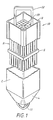
- Fig. 1 shows a cutaway sectional view of a nuclear fuel bundle or assembly 10 for a boiling water reactor ("BWR").
- the fuel bundle 10 is a discrete unit of fuel containing many individual sealed fuel elements or rods R each containing a cladding tube and nuclear fuel.
- the fuel bundle consists of a flow channel C provided at its upper end with an upper lifting bale 12 and at its lower end with a nose piece L and lower lifting bale 11.
- the upper end of channel C is open at 13 and the lower end of the nose piece is provided with coolant flow openings.
- the array of fuel elements or rods R is enclosed in channel C and supported therein by means of upper tie plate U and lower tie plate (not shown).
- one or more spacers S may be disposed within the flow channel to hold the fuel elements in alignment with one another and the flow channel.
- the liquid coolant ordinarily enters through the openings in the lower end of the nose piece, passes upwardly around fuel elements R, and discharges at upper outlet 13 in partially vaporized condition.
- PWR nuclear fuel bundles are similar in some regards to the BWR fuel bundles, there are some important differences. For example, there are no channels in the PWR fuel bundles. Further, there are more fuel rods -- as many as 17x17 or 289 -- in the bundle array. In most other regards, PWR and BWR bundles are similar. For instance, both have lifting bales and tie plates.
- CANDU reactors which are used in some Canadian reactors --have a somewhat different design, employing natural uranium dioxide in horizontally oriented cladding tubes and using heavy water as the moderator.
- the fuel elements or rods R are sealed at their ends by end plugs 18 welded to the fuel rod container 17, which may include studs 19 to facilitate the mounting of the fuel element in the fuel assembly.
- the fuel element is designed to provide excellent thermal contact between the fuel rod container 17 and the fuel material core, a minimum of parasitic neutron absorption, and resistance to bowing and vibration which is occasionally caused by flow of coolant at high velocity.
- the fuel material core is typically a plurality of fuel pellets of fissionable and/or fertile material.
- the fuel core may have various shapes, such as cylindrical pellets, spheres, or small particles.
- Various nuclear fuels may be used, including uranium compounds, thorium compounds and mixtures thereof.
- Preferred fuels include uranium dioxide or a mixture comprising uranium dioxide and plutonium dioxide.
- a void space or plenum 20 is provided at one end of the element to permit circumferential expansion of the fuel material 16 and accumulation of gases released by the fuel material.
- a getter (not shown) can be employed to remove hydrogenous impurities found in the fuel rod after manufacture.
- a nuclear fuel material retainer 24 in the form of a helical member is positioned within space 20 to provide restraint against axial movement of the pellet column during handling and transportation of the fuel element.
- Fuel element 14 includes a fuel rod container 17 surrounding a fuel material core 16.
- the container 17 is a composite cladding having a structure including a substrate 21, a zirconium barrier 22, each having circumferential inner and outer surfaces.
- the inner surface of the zirconium barrier layer contains a gold coating or liner 27.
- the substrate defines an outer circumferential region of a cladding tube, the inner coating defines an inner circumferential region, and the zirconium barrier is located between the substrate and inner coating.
- the gold inner coating is both corrosion resistant and completely hydrogen impermeable, thereby preventing hydrogen in the tube interior from reaching the zirconium barrier layer or zirconium alloy substrate.
- the cladding substrate is preferably made from a zirconium alloy.
- suitable zirconium alloys have (1) corrosion resistance to boiling water reactor (“BWR") and/or pressurized water reactor (“PWR") coolant and (2) sufficient strength and ductility for use as fuel elements.
- BWR boiling water reactor
- PWR pressurized water reactor
- Suitable zirconium alloys for the substrate preferably include at least about 98% zirconium, up to about 0.25% iron, up to about 0.1% nickel, up to about 0.25% chromium, and up to about 1.7% tin (all percents by weight).
- Other alloying elements may include niobium, bismuth, molybdenum, as well as various other elements used in the art.
- the substrate is Zircaloy-2 or Zircaloy-4.
- exemplary substrate alloys include zirconium/2.5% niobium, "NSF' alloys (about 1% tin, about 0.2-0.5% iron, about 0.05% nickel, about 0.6-1% niobium, and the balance zirconium), "Valloy” (about 0.1% iron, about 1.2% chromium, and the balance zirconium), other high chromium content alloys, and "Excel” or “Excellite” (about 0.3% niobium, about 0.3 molybdenum, about 1.2 to 1.5% tin, and the balance zirconium). Still other exemplary alloys include various bismuth-containing zirconium alloys such as those described in U.S. Patent No.
- alloys include, for example, (1) about 0.5 to 2.5 weight percent bismuth, (2) about 0.5 to 2.3 weight percent of a mixture of bismuth and tin plus about 0.5 to 1.0 weight percent of solute which may be niobium, molybdenum, tellurium, or mixtures thereof, or (3) about 0.5 to 2.5 weight percent of a mixture of tin and bismuth plus about 0.3 to 1.0 weight percent tellurium.
- a pure (or dilutely alloyed) zirconium barrier layer is metallurgically bonded to the inner surface of a Zircaloy tube (the substrate).
- the substrate provides the strength necessary to withstand the mechanical stresses induced in a nuclear reactor.
- the barrier layer provides the compliance necessary to combat the detrimental effects of a phenomenon known as pellet-cladding interaction. Pellet-cladding interaction is caused by the interactions between the nuclear fuel, the cladding, and the fission products produced during the nuclear reaction. It has been found that this undesirable effect is due to localized mechanical stresses on the fuel cladding resulting from differential expansion and friction between the fuel and the cladding in coincidence with corrosive fission product species causing stress corrosion cracking.
- the gold inner layer or coating is preferably sufficiently thick to prevent the transport of hydrogen or other hydrogen-bearing chemical species to the zirconium barrier layer.
- hydrogen-bearing specie refers to chemical species containing a hydrogen atom and including such compounds as water, hydroxyl ions (OH), and metal hydrides.
- Gold coatings will also block transport of some non-hydrogenous fission products such as nitrogen, oxygen, the noble gases, and, at low to moderate concentrations, the halogens F, Cl, Br, I and At.
- the gold coatings used in the cladding of this invention will preferably be somewhat thicker. This reduces their susceptibility to tearing and punctures during handling steps such as fuel loading.
- the gold layer is provided at a location where it is not susceptible to tearing or abrasion (e.g., between Zircaloy substrate and a zirconium barrier layer), the lower limit of gold thickness (e.g., about 100 angstroms) will be sufficient.
- the gold coatings should be thick enough to block transport of hydrogen-bearing species and resist tears, they should also be thin enough to allow penetration of thermal neutrons.
- the neutron cross section of gold is about 99 barns while that of zirconium is about 0.3 to 0.4 barns.
- the optimal thickness of the gold coating will be based on considerations of transparency to thermal neutrons.
- the gold coating should be sufficiently thin so that it does not absorb significantly more thermal neutrons than the zirconium-based cladding wall. Therefore, it is generally desirable for the gold coating to be between about 0.0001 and 0.01 times the thickness of the normal cladding. More preferably, the gold coating thickness is somewhat near 0.005 times the normal cladding thickness.
- the zirconium alloy substrate is about 750 micrometers thick and the zirconium barrier layer is about 75 micrometers thick.
- the gold coating should be between about 0.05 and 10 micrometers thick. More preferably, the gold coating should be between about 0.5 and 10 micrometers thick, and even more preferably between about 1 and 5 micrometers thick.
- the present invention provides a gold coated three-layer cladding including a substrate, a barrier, and, in addition, an inner liner.
- the substrate and the barrier layer may take the same form as described above.
- the inner liner matrix is preferably Zircaloy or another zirconium alloy.
- the inner liner protects the zirconium barrier layer from oxidation should water enter the cladding tube interior.
- the structure 47 includes a gold coating 45 on a three-layer fuel cladding including a substrate 41, a zirconium barrier 42, and an inner layer or liner 43.
- the substrate forms the outer circumferential region of a cladding tube
- the inner liner forms an inner circumferential region
- the zirconium barrier is located between the substrate and inner liner.
- the inner liner 43 is corrosion resistant and thereby protects the zirconium barrier from rapid oxidation should the fuel element interior come in contact with steam.
- the inner liner should be made from a layer on a highly corrosion resistant material such as a zirconium alloy (e.g., a modified Zircaloy).
- the gold coating 45 protects the inner liner 43 from hydrogen bearing species.
- the gold coating is preferably located on the inner surface of the cladding, it can also provide protection at other locations in the cladding.
- the gold coating may be located on the outer surface of the substrate (i.e., coating the exterior circumferential surface of the substrate). This protects the cladding from hydride damage due to hydrogen-bearing species in the moderator or other media contacting the cladding exterior.
- the gold coating may located within the cladding wall, between the substrate and the zirconium barrier layer of the cladding. This arrangement would still protect the substrate (the principal structural member of the fuel element) from hydride damage resulting from hydrogen-bearing species originating in the fuel element interior.
- cladding structures having an inner liner the gold coating could be located between either (1) the inner liner and the zirconium barrier layer, or (2) the zirconium barrier layer and the substrate. Cladding having the gold coating disposed as described within the cladding wall (as opposed to the cladding interior or exterior) is less likely to tear or puncture in response to handling. Multiple layers of gold can be used in these same locations with the proviso that the sum of the thicknesses of these multiple layers is less than the thickness limitation specified previously.
- a cladding tube may include a first 1 micrometer thick gold layer provided between the substrate and barrier layer, and a second 1 micrometer thick gold layer provided between the zirconium layer and the inner liner.
- the gold coating is initially provided as a sleeve that is bonded with other components of the cladding.
- the substrate is initially prepared from a beta quenched ingot of suitable zirconium alloy such as Zircaloy-2 or Zircaloy4.
- the ingot is machined to form a hollow billet which is then bonded with the gold sleeve to form a tubeshell. Because gold is very ductile and malleable down to room temperatures, there is no low temperature limit on the bonding step arising from the use of gold as a barrier layer.
- the bonding step involves coextrusion of the zirconium alloy billet with the gold sleeve at temperatures of less than about 1063 °C.
- the extruded tubeshell is then reduced to a final tubing size by a series of cold tube reduction steps (e.g. pilgering steps), each followed by an annealing step at temperatures of up to 650°C.
- the final reduction step is followed by a final annealing at a temperature selected to give either completely recrystallized final tubing or partially recrystallized tubing, depending on the desired mechanical properties and the application of the tubing.
- a zirconium alloy billet is prepared as above and then bonded (preferably by coextrusion) with a zirconium sleeve and a gold sleeve. If a three-layer cladding is to be formed, a zirconium alloy inner sleeve is also includes in the bonding step(s). Details of suitable processes for forming three layer structures having inner liners, zirconium barrier layers, and substrates can be found in U.S. Patent Application No.
- the various cladding components can be coextruded in separate steps.
- the substrate and zirconium barrier layer can be coextruded in a first step followed by coextrusion of the resulting structure with a gold sleeve in a second step.
- at least some of the cladding components can be bonded to one another by processes other than extrusion. Such processes include, by way of example, hot isostatic pressing, explosive bonding, and diffusion annealing.
- the gold is provided as thin leaves which are burnished onto the cladding tube interior surface.
- the leaves are wrapped on a dow of Teflon or other suitable material and then inserted into the tube interior on the dow.
- the dow is subsequently rolled inside the cladding tube causing the gold leaves to preferentially adhere to the cladding tube interior.
- the gold coating is applied to the zirconium or zirconium alloy surface of the cladding tube by a conventional electrochemical or an electroless chemical process.
- the gold can be electroplated onto the inner surface of a cladding tube prepared by conventional processing.
- One suitable electroplating process involves providing a gold chloride (AuCl3) aqueous solution in the cladding tube interior.
- the gold ions in the salt solution are then plated out on the cladding tube interior surface by holding the cladding tube at a cathodic potential.
- Various suitable anodes can be used.
- the anode is a gold wire held axially in the cladding interior and maintained at an anodic potential.
- Vendors of suitable products for gold electroplating include Norbert Plating Company, 340-T N. Ashland Ave., Chicago, III., 60607; Acteron Corporation, 851 Shasta Street, Redwood City, CA 94063; American Electro Products, 1360 Thomaston Avenue, Waterbury, Conn., 06704; and International Technical Associates, 2281 Calle de Luna, Santa Clara, CA, 95054.
- Suitable process conditions for gold plating are provided in various well-known references such as L. I. Maissel & R. Glang, Handbook of Thin Film Technology , McGraw Hill, NY, pages 5-9 (1970) which is incorporated herein by reference for all purposes.
- Suitable solutions for electroless gold plating are provided by Epner Technology Inc., 25 Division Place, Brooklyn, NY 11222; MacDermid Inc., Waterbury Conn. 06704; Acteron Corporation, 851 Shasta Street, Redwood City, CA 94063; and International Technical Associates, 2281 Calle de Luna, Santa Clara, CA, 95054.
- Such solutions may include, for example, a few parts per billion of a palladium salt (which acts as a catalyst) together with AuCl3 and organic compounds which will support an organic addition reaction. Further details of suitable electroless gold plating processes are found in the Maissel and Glang handbook previously incorporated by reference.
- gold is evaporated onto the cladding tube interior surface.
- a tungsten wire coated with gold is inserted into an evacuated cladding tube interior. Sufficient current is then passed through the tungsten causing the temperature of the wire to rise to approximately 1200° C. At this temperature the vapor pressure of gold is sufficiently high that it evaporates and deposits on the relatively cool zirconium inner surface to form a gold coating of thickness suitable for this invention.
- additional details of this process may be found in the Maissel and Glang handbook previously incorporated by reference.
- the gold coating is formed by chemical vapor deposition. Because cladding tubes have long thin profiles (e.g., 5 meters long by one centimeter), conventional chemical vapor deposition processes may require some modification to provide a sufficiently uniform gold coating.
- One suitable method involves providing a gold wire along the cladding interior axis and filling the interior with chlorine gas. The gold wire is then heated to approximately 900-1000° C by passing current through the wire. The cladding tube interior is held at approximately 700° C. Under these conditions, the chlorine gas reacts with the gold wire to form gaseous (AuCl)2 which is stable at about 900° C.
- the gaseous (AuCl)2 so formed diffuses to the cooler cladding wall where it is no longer stable (because of the lower temperature) and decomposes to release gold metal and chlorine gas.
- the chlorine gas then diffuses back to the hotter gold wire where it reacts with the solid gold to form more (AuCl)2.
- a uniform gold coating of sufficient thickness for this invention is formed. See for example, " Chemical Transport Reactions ,” H. Schafer, Academic Press NY, p. 39 (1964) which is incorporated herein by reference for all purposes.
- the gold coating may be applied to other nuclear reactor components susceptible to hydrogen damage as well.
- fuel element end plugs, spacers, tie rods, tie plates, flow channels, water rods, and control tubes may also be gold coated in accordance with this invention.
- the gold used herein can be used in forms other than pure unalloyed gold.
- the cladding tubes here taught may be coated with gold alloys and their equivalents in which hydrogen and hydrogen bearing species are substantially or completely insoluble. That is, the present invention, in its broadest aspect, envisages a zirconium alloy nuclear reactor component having a coating which is substantially insoluble to hydrogen and hydrogen bearing species, the coating being sufficiently thin to pass a significant neutron flux from fissionable fuel.
Landscapes
- Physics & Mathematics (AREA)
- Engineering & Computer Science (AREA)
- Plasma & Fusion (AREA)
- General Engineering & Computer Science (AREA)
- High Energy & Nuclear Physics (AREA)
- Monitoring And Testing Of Nuclear Reactors (AREA)
- Chemically Coating (AREA)
- Other Surface Treatments For Metallic Materials (AREA)
Applications Claiming Priority (2)
| Application Number | Priority Date | Filing Date | Title |
|---|---|---|---|
| US274518 | 1988-11-22 | ||
| US27451894A | 1994-07-13 | 1994-07-13 |
Publications (1)
| Publication Number | Publication Date |
|---|---|
| EP0692792A1 true EP0692792A1 (fr) | 1996-01-17 |
Family
ID=23048528
Family Applications (1)
| Application Number | Title | Priority Date | Filing Date |
|---|---|---|---|
| EP95304465A Withdrawn EP0692792A1 (fr) | 1994-07-13 | 1995-06-26 | Chemise de combustible nucléaire |
Country Status (3)
| Country | Link |
|---|---|
| EP (1) | EP0692792A1 (fr) |
| JP (1) | JPH08170992A (fr) |
| TW (1) | TW258815B (fr) |
Cited By (1)
| Publication number | Priority date | Publication date | Assignee | Title |
|---|---|---|---|---|
| EP1703523A3 (fr) * | 2005-03-14 | 2008-01-23 | General Electric Company | Procédés de réduction de l'absorption d'hydrogène dans des alliages de zircone d'un ensemble à combustible nucléaire |
Families Citing this family (2)
| Publication number | Priority date | Publication date | Assignee | Title |
|---|---|---|---|---|
| WO2009150710A1 (fr) * | 2008-06-09 | 2009-12-17 | 原子燃料工業株式会社 | Combustible pour réacteur à eau lourde ou réacteur à graphite et son procédé de production |
| JP5597375B2 (ja) * | 2009-04-10 | 2014-10-01 | 株式会社東芝 | 高速炉、照射集合体、照射ピン及び照射ペレット |
Citations (13)
| Publication number | Priority date | Publication date | Assignee | Title |
|---|---|---|---|---|
| US3085059A (en) * | 1958-10-02 | 1963-04-09 | Gen Motors Corp | Fuel element for nuclear reactors |
| DE1903009A1 (de) | 1969-01-22 | 1970-09-03 | Kernenergieverwert Ges Fuer | Bauelement aus Zirkon oder einer Zirkonlegierung |
| FR2317372A1 (fr) * | 1975-06-26 | 1977-02-04 | Gen Electric | Procede d'amelioration de la resistance a la corrosion de pieces en alliage de zirconium et pieces ainsi obtenues. |
| JPS54121386A (en) * | 1978-03-14 | 1979-09-20 | Toshiba Corp | Nuclear fuel element |
| US4200492A (en) | 1976-09-27 | 1980-04-29 | General Electric Company | Nuclear fuel element |
| GB2064201A (en) * | 1979-11-26 | 1981-06-10 | Gen Electric | Hydrogen Resistant Nuclear Fuel Container |
| US4372817A (en) | 1976-09-27 | 1983-02-08 | General Electric Company | Nuclear fuel element |
| US4610842A (en) | 1983-03-30 | 1986-09-09 | Ab Asea-Atom | Fuel rod for a nuclear reactor |
| US4659545A (en) | 1984-05-07 | 1987-04-21 | Westinghouse Electric Corp. | Hydride blister-resistant zirconium-based nuclear fuel rod cladding |
| EP0326896A1 (fr) * | 1988-02-05 | 1989-08-09 | General Electric Company | Elément de combustible nucléaire à revêtement résistant à l'oxydation |
| US4876064A (en) | 1987-04-23 | 1989-10-24 | General Electric Company | Corrosion resistant zirconium alloys containing bismuth |
| US9167293B2 (en) | 2011-08-31 | 2015-10-20 | Kabushiki Kaisha Toshiba | Electronic device and method of transmitting content item |
| US9218893B2 (en) | 2012-09-28 | 2015-12-22 | Lenovo Enterprise Solutions (Singapore) Pte. Ltd. | Memory testing in a data processing system |
-
1995
- 1995-02-07 TW TW084100995A patent/TW258815B/zh not_active IP Right Cessation
- 1995-06-26 EP EP95304465A patent/EP0692792A1/fr not_active Withdrawn
- 1995-07-07 JP JP7171240A patent/JPH08170992A/ja not_active Withdrawn
Patent Citations (14)
| Publication number | Priority date | Publication date | Assignee | Title |
|---|---|---|---|---|
| US3085059A (en) * | 1958-10-02 | 1963-04-09 | Gen Motors Corp | Fuel element for nuclear reactors |
| DE1903009A1 (de) | 1969-01-22 | 1970-09-03 | Kernenergieverwert Ges Fuer | Bauelement aus Zirkon oder einer Zirkonlegierung |
| FR2317372A1 (fr) * | 1975-06-26 | 1977-02-04 | Gen Electric | Procede d'amelioration de la resistance a la corrosion de pieces en alliage de zirconium et pieces ainsi obtenues. |
| US4372817A (en) | 1976-09-27 | 1983-02-08 | General Electric Company | Nuclear fuel element |
| US4200492A (en) | 1976-09-27 | 1980-04-29 | General Electric Company | Nuclear fuel element |
| JPS54121386A (en) * | 1978-03-14 | 1979-09-20 | Toshiba Corp | Nuclear fuel element |
| GB2064201A (en) * | 1979-11-26 | 1981-06-10 | Gen Electric | Hydrogen Resistant Nuclear Fuel Container |
| US4610842A (en) | 1983-03-30 | 1986-09-09 | Ab Asea-Atom | Fuel rod for a nuclear reactor |
| US4659545A (en) | 1984-05-07 | 1987-04-21 | Westinghouse Electric Corp. | Hydride blister-resistant zirconium-based nuclear fuel rod cladding |
| US4876064A (en) | 1987-04-23 | 1989-10-24 | General Electric Company | Corrosion resistant zirconium alloys containing bismuth |
| EP0326896A1 (fr) * | 1988-02-05 | 1989-08-09 | General Electric Company | Elément de combustible nucléaire à revêtement résistant à l'oxydation |
| US4894203A (en) | 1988-02-05 | 1990-01-16 | General Electric Company | Nuclear fuel element having oxidation resistant cladding |
| US9167293B2 (en) | 2011-08-31 | 2015-10-20 | Kabushiki Kaisha Toshiba | Electronic device and method of transmitting content item |
| US9218893B2 (en) | 2012-09-28 | 2015-12-22 | Lenovo Enterprise Solutions (Singapore) Pte. Ltd. | Memory testing in a data processing system |
Non-Patent Citations (3)
| Title |
|---|
| H. SCHAFER: "Chemical Transport Reactions", 1964, ACADEMIC PRESS, NY, pages: 39 |
| L.I.MAISSEL & R. GLANG: "Handbook of Thin Film Technology", 1970, MCGRAW HILL, NY, pages: 5 - 9 |
| PATENT ABSTRACTS OF JAPAN vol. 3, no. 144 (M - 082) 28 November 1979 (1979-11-28) * |
Cited By (1)
| Publication number | Priority date | Publication date | Assignee | Title |
|---|---|---|---|---|
| EP1703523A3 (fr) * | 2005-03-14 | 2008-01-23 | General Electric Company | Procédés de réduction de l'absorption d'hydrogène dans des alliages de zircone d'un ensemble à combustible nucléaire |
Also Published As
| Publication number | Publication date |
|---|---|
| JPH08170992A (ja) | 1996-07-02 |
| TW258815B (en) | 1995-10-01 |
Similar Documents
| Publication | Publication Date | Title |
|---|---|---|
| US5341407A (en) | Inner liners for fuel cladding having zirconium barriers layers | |
| US4029545A (en) | Nuclear fuel elements having a composite cladding | |
| FI92355B (fi) | Ydinpolttoaine-elementti sekä menetelmä ydinpolttoaineen komposiittiverhoussäiliön käsittelemiseksi | |
| US4200492A (en) | Nuclear fuel element | |
| US4372817A (en) | Nuclear fuel element | |
| US5247550A (en) | Corrosion resistant zirconium liner for nuclear fuel rod cladding | |
| US5434897A (en) | Hydride damage resistant fuel elements | |
| US4022662A (en) | Nuclear fuel element having a metal liner and a diffusion barrier | |
| US4045288A (en) | Nuclear fuel element | |
| US4406012A (en) | Nuclear fuel elements having a composite cladding | |
| US5524032A (en) | Nuclear fuel cladding having an alloyed zirconium barrier layer | |
| EP0624882A1 (fr) | Chemisage en zircaloy ayant une résistance élevée à la propagation des fissures | |
| US4717534A (en) | Nuclear fuel cladding containing a burnable absorber | |
| US5475723A (en) | Nuclear fuel cladding with hydrogen absorbing inner liner | |
| US4445942A (en) | Method for forming nuclear fuel containers of a composite construction and the product thereof | |
| US4659540A (en) | Composite construction for nuclear fuel containers | |
| CA1198231A (fr) | Ecran en alliage de zirconium offrant une resistance accrue a la corrosion | |
| CA1209726A (fr) | Ecran en alliage de zircone a resistance accrue a la corrosion | |
| US5867552A (en) | Zirconium-based two-phase alloys for hydride resistant nuclear reactor components | |
| EP0692792A1 (fr) | Chemise de combustible nucléaire | |
| JPH0160797B2 (fr) | ||
| CA1209727A (fr) | Couche-ecran incorporee en zircone | |
| JPH0373832B2 (fr) | ||
| JP2026007265A (ja) | 燃料集合体および燃料集合体の製造方法 | |
| JPH04204196A (ja) | 核燃料要素 |
Legal Events
| Date | Code | Title | Description |
|---|---|---|---|
| PUAI | Public reference made under article 153(3) epc to a published international application that has entered the european phase |
Free format text: ORIGINAL CODE: 0009012 |
|
| AK | Designated contracting states |
Kind code of ref document: A1 Designated state(s): CH DE ES IT LI |
|
| 17P | Request for examination filed |
Effective date: 19960717 |
|
| 17Q | First examination report despatched |
Effective date: 19970206 |
|
| STAA | Information on the status of an ep patent application or granted ep patent |
Free format text: STATUS: THE APPLICATION IS DEEMED TO BE WITHDRAWN |
|
| 18D | Application deemed to be withdrawn |
Effective date: 20030123 |