EP0692921A1 - Schallaufnahmevorrichtung durch Elektretmikrofon - Google Patents
Schallaufnahmevorrichtung durch Elektretmikrofon Download PDFInfo
- Publication number
- EP0692921A1 EP0692921A1 EP95401674A EP95401674A EP0692921A1 EP 0692921 A1 EP0692921 A1 EP 0692921A1 EP 95401674 A EP95401674 A EP 95401674A EP 95401674 A EP95401674 A EP 95401674A EP 0692921 A1 EP0692921 A1 EP 0692921A1
- Authority
- EP
- European Patent Office
- Prior art keywords
- electret microphone
- input
- differential
- preamplifier stage
- symmetrical
- Prior art date
- Legal status (The legal status is an assumption and is not a legal conclusion. Google has not performed a legal analysis and makes no representation as to the accuracy of the status listed.)
- Granted
Links
Images


Classifications
-
- H—ELECTRICITY
- H04—ELECTRIC COMMUNICATION TECHNIQUE
- H04R—LOUDSPEAKERS, MICROPHONES, GRAMOPHONE PICK-UPS OR LIKE ACOUSTIC ELECTROMECHANICAL TRANSDUCERS; ELECTRIC HEARING AIDS; PUBLIC ADDRESS SYSTEMS
- H04R19/00—Electrostatic transducers
- H04R19/04—Microphones
-
- H—ELECTRICITY
- H04—ELECTRIC COMMUNICATION TECHNIQUE
- H04R—LOUDSPEAKERS, MICROPHONES, GRAMOPHONE PICK-UPS OR LIKE ACOUSTIC ELECTROMECHANICAL TRANSDUCERS; ELECTRIC HEARING AIDS; PUBLIC ADDRESS SYSTEMS
- H04R1/00—Details of transducers, loudspeakers or microphones
- H04R1/02—Casings; Cabinets ; Supports therefor; Mountings therein
- H04R1/04—Structural association of microphone with electric circuitry therefor
-
- H—ELECTRICITY
- H04—ELECTRIC COMMUNICATION TECHNIQUE
- H04R—LOUDSPEAKERS, MICROPHONES, GRAMOPHONE PICK-UPS OR LIKE ACOUSTIC ELECTROMECHANICAL TRANSDUCERS; ELECTRIC HEARING AIDS; PUBLIC ADDRESS SYSTEMS
- H04R19/00—Electrostatic transducers
- H04R19/01—Electrostatic transducers characterised by the use of electrets
- H04R19/016—Electrostatic transducers characterised by the use of electrets for microphones
Definitions
- the invention relates to a sound pickup device by electret microphone.
- the final cost of the product essentially depends on the type of microphone used, the cost of this varying directly as a result of its quality.
- the overall cost can become very high.
- Dynamic microphones are generally used for sound recording in shows and in the studio, because of their very high quality, but their high price and their irreducible size do not make them suitable for sound recording for telephone terminals, or any making sound economic.
- Electret microphones providing a weak useful signal, require a preamplifier in order to bring the output signal of the electret capsule at a level of the order of a volt.
- the electret capsule must be supplied with electrical energy, since it incorporates a field effect transistor.
- the electret microphone M comprising a point connected to ground and a point receiving the electrical supply and delivering the useful audio signal, the usual arrangement is shown in FIG. 1a.
- the output level of the useful signal which varies from a few hundred microvolts to a few tens of millivolts, depending on the sensitivity of the capsules and the position of the microphone relative to the source, i.e.
- this mounting requires the implementation of a high gain preamplification stage.
- the presence of this significant gain makes the assembly very sensitive to power supply noise and electromagnetic disturbances. Indeed, if the supply voltage VM is not perfectly regulated, the variations thereof are seen as a useful signal by the preamplification stage. The same is true for electromagnetic radiation or parasites, which affect the useful input of the preamplification stage.
- Such sound recording systems are said to be noisy, because these, on the one hand, have a low signal-to-noise ratio when the power supply is not perfectly regulated, rate of change less than or equal to 0.5% , and, on the other hand, are very sensitive to parasitic electromagnetic radiation, 50 Hz, if the assembly is not perfectly shielded.
- the object of the present invention is to remedy the aforementioned drawbacks by using a device for picking up sound by an electret microphone of the differential type in which any transformer is omitted.
- Another object of the present invention is also the implementation of a sound pickup device by good quality electret microphone, due to its operation in differential mode.
- the device for taking sound from an electret microphone, object of the present invention in which signals delivered by the electret microphone are amplified by means of a differential preamplifier stage, is remarkable in that it comprises a link by connection capacity between each output terminal of the electret microphone and an input of the differential preamplifier stage.
- a symmetrical bias circuit of the output terminals an electret microphone is provided, which comprises a first and a second voltage source, symmetrical with respect to a reference voltage, and each connected to an output terminal of the electret microphone.
- the electret microphone sound pickup device finds application in the production of quality sound pickup systems in the field of telecommunications, voice recognition, acoustic antennas.
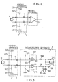
- FIG. 2 it is indicated that the same references indicate the same elements as in FIGS. 1a and 1b relating to the prior art.
- the sound pickup device comprises, as shown in FIG. 2 above, a link 1 per link capacity between each output terminal of the electret microphone M and an input of the differential preamplifier stage 3.
- the link capacities bear the reference 11 and 12 on the figure 2.
- a symmetrical bias circuit of the output terminals of the electret microphone M is provided, this circuit bearing the reference 2 in the aforementioned FIG. 2.
- first 21 and a second 22 voltage source the voltages supplied by the sources 21 and 22 being symmetrical with respect to a reference voltage of the device, the mass of the sound pickup device.
- Each voltage source 21, 22 is connected via a resistor 210, respectively 220, to an output terminal of the electret microphone M.
- the polarization device 2 must be symmetrical, the supply voltages -VM and + VM delivered by sources 21 and 22 being opposite, resistors 210 and 220 and capacitors 11 and 12 being identical, for rejection in common mode.
- the differential preamplifier stage 3 can advantageously comprise on each input channel a preamplifier device in non-differential mode, carrying the reference 30 respectively 31.
- the preamplifiers in non-differential mode 30 and 31 can conventionally include a positive terminal forming an input terminal for the signals delivered by the connection capacitors 11 respectively. 12, and a resistive feedback coupling via resistors 301 and 311 respectively on the corresponding negative terminal.
- the output resistors 302 and 312 make it possible to drive a differential output amplifier 32, which can conventionally include a positive terminal forming an input terminal connected to the output of the preamplifier 31 via a resistor 321 and d a capacitor 322 in parallel connected between the aforementioned positive input terminal and the reference voltage, and a negative input terminal connected on the one hand, in feedback by a 320 capacitor circuit 323 to the output terminal of the amplifier 32, and, on the other hand, to the resistor 302 of the output of the preamplifier device in non-differential mode 30.
- each preamplifier device in non-differential mode 30 and 31 is connected to the reference voltage by means of an input resistor 300, respectively 310.
- an adjustable resistor 313 is provided, this resistor connecting the two negative inputs of each preamplifier device in non-differential mode 30 and 31.
- the resistor 313 may include a non-adjustable fixed resistor of non-zero value and thus allows to carry out a gain adjustment adjustment in non-differential mode of the aforementioned non-differential preamplifier devices 30 and 31.
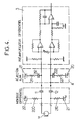
- a noticeable improvement of the device, object of the present invention, as shown in Figure 3, can then be made, as shown in Figure 4, in order to reduce the noise inherent in the two supply voltages 21 and 22 in the case in particular where non-symmetrical noise disturbances would appear on these supplies.
- the electret microphone sound recording device further comprises, between the differential preamplifier stage 3 and the link by link capacity, on each input channels of the aforementioned differential preamplifier stage 3, an inverted coupling circuit of each of the input channels to the symmetrical bias circuit.
- This inverted coupling circuit called supply rejection, makes it possible to reinject at each input terminal of the differential preamplifier stage the voltages delivered by the symmetrical inverted voltage sources, deprived of their continuous components.
- each input of the differential amplifier stage 3 thus sees the sum of the noises of the two aforementioned supplies 21 and 22, this noise then disappearing at the output since the assembly effects the difference of the input signals.
- the coupling circuit 4 comprises a first and a second circuit, each formed by a resistor and an electric capacitor in series, bearing the references 211, 212, respectively 221, 222.
- the first circuit 211, 212 is connected between the second negative voltage source 21 and the first input of the differential amplifier stage 3, that is to say downstream of the connection capacity 11
- the second circuit 221, 222 is connected between the first positive voltage source 20 and the second input of the differential preamplifier stage 3, that is to say downstream of the connection capacitor 12.
- the power rejection circuit 4 must be identical to the bias circuit 2, the resistor 211 being identical to the resistor 210, the resistor 221 identical to the resistor 220, the capacity 212 identical at capacity 12 and capacity 222 identical to capacity 11.
- Figure 5a the response of the assembly of the prior art shown in Figure la to a disturbance of the power supply sector, that is to say at a frequency of 50 Hz.
- Figure 5a is graduated on the ordinate in decibels and, on the abscissa, in frequencies. The tests were carried out in the presence of a pink noise and a line at 50 Hz due to a disturbance of the sector as well as to the harmonic frequencies of the latter.
- the response of the circuit as shown in FIG. 1 relating to the prior art, clearly exhibits parasitic noise at the frequency of the sector mentioned above.
- the device for picking up sound by electret microphone, object of the present invention, previously described, is particularly advantageous insofar as, by the mere replacement of the transformer by a coupling circuit by capacitance link, the results, in terms of pick-up its, however, are identical to the circuits of the prior art comprising such transformers, while the cost price of implementation of these circuits have been known to be reduced.
- circuits in accordance with the object of the present invention, is particularly advantageous in acoustic antennas or in complex circuits requiring quality sound recording.
Landscapes
- Physics & Mathematics (AREA)
- Engineering & Computer Science (AREA)
- Acoustics & Sound (AREA)
- Signal Processing (AREA)
- Circuit For Audible Band Transducer (AREA)
- Soundproofing, Sound Blocking, And Sound Damping (AREA)
Applications Claiming Priority (2)
| Application Number | Priority Date | Filing Date | Title |
|---|---|---|---|
| FR9408807 | 1994-07-15 | ||
| FR9408807A FR2722636B1 (fr) | 1994-07-15 | 1994-07-15 | Dispositif de prise de son par microphone electret |
Publications (2)
| Publication Number | Publication Date |
|---|---|
| EP0692921A1 true EP0692921A1 (de) | 1996-01-17 |
| EP0692921B1 EP0692921B1 (de) | 2001-10-04 |
Family
ID=9465436
Family Applications (1)
| Application Number | Title | Priority Date | Filing Date |
|---|---|---|---|
| EP19950401674 Expired - Lifetime EP0692921B1 (de) | 1994-07-15 | 1995-07-12 | Schallaufnahmevorrichtung durch Elektretmikrofon |
Country Status (4)
| Country | Link |
|---|---|
| EP (1) | EP0692921B1 (de) |
| DE (1) | DE69523004T2 (de) |
| ES (1) | ES2164140T3 (de) |
| FR (1) | FR2722636B1 (de) |
Cited By (2)
| Publication number | Priority date | Publication date | Assignee | Title |
|---|---|---|---|---|
| FR2769164A1 (fr) * | 1997-09-26 | 1999-04-02 | Alain Maurice Ange Magagnini | Dispositif micro electrostatique a interface circuit integre |
| GB2382949A (en) * | 2001-12-04 | 2003-06-11 | Samsung Electronics Co Ltd | Reducing echoes and noise caused by cross talk in a telephone handset connecting cord |
Citations (5)
| Publication number | Priority date | Publication date | Assignee | Title |
|---|---|---|---|---|
| US3778561A (en) * | 1972-06-21 | 1973-12-11 | Bell Canada Northern Electric | Electret microphone |
| EP0055650A1 (de) * | 1980-12-31 | 1982-07-07 | Thomson-Csf Telephone | Schaltung zur Verbindung eines aktiven Mikrophons, insbesondere mit Elektret, mit einer Fernsprechübertragungsschaltung |
| DE3933870A1 (de) * | 1989-10-11 | 1991-04-18 | Neumann Gmbh Georg | Verfahren und schaltungsanordnung zum steuern von mikrofonen |
| EP0546571A1 (de) * | 1991-12-12 | 1993-06-16 | Nec Corporation | Verstärkerschaltungsanordnung für ein Elektret-Kondensator Mikrofon |
| US5315231A (en) * | 1992-11-16 | 1994-05-24 | Hughes Aircraft Company | Symmetrical bipolar bias current source with high power supply rejection ratio (PSRR) |
-
1994
- 1994-07-15 FR FR9408807A patent/FR2722636B1/fr not_active Expired - Lifetime
-
1995
- 1995-07-12 EP EP19950401674 patent/EP0692921B1/de not_active Expired - Lifetime
- 1995-07-12 DE DE1995623004 patent/DE69523004T2/de not_active Expired - Lifetime
- 1995-07-12 ES ES95401674T patent/ES2164140T3/es not_active Expired - Lifetime
Patent Citations (5)
| Publication number | Priority date | Publication date | Assignee | Title |
|---|---|---|---|---|
| US3778561A (en) * | 1972-06-21 | 1973-12-11 | Bell Canada Northern Electric | Electret microphone |
| EP0055650A1 (de) * | 1980-12-31 | 1982-07-07 | Thomson-Csf Telephone | Schaltung zur Verbindung eines aktiven Mikrophons, insbesondere mit Elektret, mit einer Fernsprechübertragungsschaltung |
| DE3933870A1 (de) * | 1989-10-11 | 1991-04-18 | Neumann Gmbh Georg | Verfahren und schaltungsanordnung zum steuern von mikrofonen |
| EP0546571A1 (de) * | 1991-12-12 | 1993-06-16 | Nec Corporation | Verstärkerschaltungsanordnung für ein Elektret-Kondensator Mikrofon |
| US5315231A (en) * | 1992-11-16 | 1994-05-24 | Hughes Aircraft Company | Symmetrical bipolar bias current source with high power supply rejection ratio (PSRR) |
Cited By (6)
| Publication number | Priority date | Publication date | Assignee | Title |
|---|---|---|---|---|
| FR2769164A1 (fr) * | 1997-09-26 | 1999-04-02 | Alain Maurice Ange Magagnini | Dispositif micro electrostatique a interface circuit integre |
| GB2382949A (en) * | 2001-12-04 | 2003-06-11 | Samsung Electronics Co Ltd | Reducing echoes and noise caused by cross talk in a telephone handset connecting cord |
| AU2002302014B2 (en) * | 2001-12-04 | 2004-08-19 | Samsung Electronics Co., Ltd. | Apparatus for reducing echoes and noises in telephone |
| GB2382949B (en) * | 2001-12-04 | 2004-09-29 | Samsung Electronics Co Ltd | Apparatus for reducing echoes and noises in telephone equipment |
| AU2002302014B9 (en) * | 2001-12-04 | 2005-03-24 | Samsung Electronics Co., Ltd. | Apparatus for reducing echoes and noises in telephone |
| US6934383B2 (en) | 2001-12-04 | 2005-08-23 | Samsung Electronics Co., Ltd. | Apparatus for reducing echoes and noises in telephone |
Also Published As
| Publication number | Publication date |
|---|---|
| DE69523004T2 (de) | 2002-06-06 |
| FR2722636B1 (fr) | 1996-09-20 |
| FR2722636A1 (fr) | 1996-01-19 |
| DE69523004D1 (de) | 2001-11-08 |
| ES2164140T3 (es) | 2002-02-16 |
| EP0692921B1 (de) | 2001-10-04 |
Similar Documents
| Publication | Publication Date | Title |
|---|---|---|
| EP1012609B1 (de) | Gerät mit bandpass grosser bandbreite zum messen elektrischer stromstärke in einem leiter | |
| EP2304872B1 (de) | Schaltung zum verstärken eines signals, das eine widerstandsschwankung eines variablen widerstands und entsprechenden kondensators repräsentiert | |
| EP1292171A2 (de) | Chip-Mikrofon und Verfahren zu seiner Herstellung | |
| FR2684251A1 (fr) | Moteur lineaire asservi a reluctance variable. | |
| JP2023540983A (ja) | レーザマイクロフォン及び端末 | |
| FR2719425A1 (fr) | Amplificateur différentiel à réglage de mode commun. | |
| FR2857551A1 (fr) | Dispositif pour capter ou reproduire des signaux audio | |
| FR2485828A1 (fr) | Circuit comportant deux amplificateurs differentiels couples en croix | |
| EP0543708A1 (de) | Ultraschnelle Differenzverstärker | |
| EP0692921B1 (de) | Schallaufnahmevorrichtung durch Elektretmikrofon | |
| EP3637792B1 (de) | Steuerungsvorrichtung eines lautsprechers und entsprechende klangwiedergabeanlage | |
| EP2888815A1 (de) | Analoge verstärkungsvorrichtung, insbesondere für ein laser-anemometer | |
| EP0055650B1 (de) | Schaltung zur Verbindung eines aktiven Mikrophons, insbesondere mit Elektret, mit einer Fernsprechübertragungsschaltung | |
| FR2857798A1 (fr) | Amplificateur de tension a faible consommation. | |
| FR2504753A1 (fr) | Circuit detecteur de niveau | |
| EP0296992B1 (de) | Schaltkreis zum Schalten der Leseköpfe eines Videorecorders | |
| WO1988004124A1 (fr) | Dispositif de traitement d'un signal electrique audiofrequence | |
| EP0305301B1 (de) | Signalkompressorschaltung, insbesondere für Fernsprechapparate | |
| FR3098673A1 (fr) | Microphone électret omnidirectionnel avec étage adaptateur d’impédance à amplificateur opérationnel en particulier pour des applications de détection sur piles | |
| EP0847193A1 (de) | Zwischenfrequenzverstärker für Funkwellenempfänger | |
| FR2532492A1 (fr) | Circuit amplificateur audio | |
| CA2051882A1 (fr) | Dispositif de traitement d'un signal provenant d'un capteur ayant une reponse du type derivatif | |
| FR2464594A1 (fr) | Reseau de regulation parallele d'une tension electrique, notamment la tension d'une ligne telephonique pour un poste d'abonne a circuits electroniques | |
| FR2884984A1 (fr) | Dispositif d'amplification de puissance d'un signal audiophonique et systeme d'amplification symetrique utilisant un tel dispositif | |
| FR2515468A1 (fr) | Ecouteur dynamique |
Legal Events
| Date | Code | Title | Description |
|---|---|---|---|
| PUAI | Public reference made under article 153(3) epc to a published international application that has entered the european phase |
Free format text: ORIGINAL CODE: 0009012 |
|
| AK | Designated contracting states |
Kind code of ref document: A1 Designated state(s): DE ES GB IT |
|
| 17P | Request for examination filed |
Effective date: 19960102 |
|
| 17Q | First examination report despatched |
Effective date: 19991111 |
|
| GRAG | Despatch of communication of intention to grant |
Free format text: ORIGINAL CODE: EPIDOS AGRA |
|
| GRAG | Despatch of communication of intention to grant |
Free format text: ORIGINAL CODE: EPIDOS AGRA |
|
| GRAH | Despatch of communication of intention to grant a patent |
Free format text: ORIGINAL CODE: EPIDOS IGRA |
|
| GRAH | Despatch of communication of intention to grant a patent |
Free format text: ORIGINAL CODE: EPIDOS IGRA |
|
| GRAA | (expected) grant |
Free format text: ORIGINAL CODE: 0009210 |
|
| AK | Designated contracting states |
Kind code of ref document: B1 Designated state(s): DE ES GB IT |
|
| REF | Corresponds to: |
Ref document number: 69523004 Country of ref document: DE Date of ref document: 20011108 |
|
| REG | Reference to a national code |
Ref country code: GB Ref legal event code: IF02 |
|
| GBT | Gb: translation of ep patent filed (gb section 77(6)(a)/1977) |
Effective date: 20011214 |
|
| REG | Reference to a national code |
Ref country code: ES Ref legal event code: FG2A Ref document number: 2164140 Country of ref document: ES Kind code of ref document: T3 |
|
| PLBE | No opposition filed within time limit |
Free format text: ORIGINAL CODE: 0009261 |
|
| STAA | Information on the status of an ep patent application or granted ep patent |
Free format text: STATUS: NO OPPOSITION FILED WITHIN TIME LIMIT |
|
| 26N | No opposition filed | ||
| PGFP | Annual fee paid to national office [announced via postgrant information from national office to epo] |
Ref country code: GB Payment date: 20140624 Year of fee payment: 20 |
|
| PGFP | Annual fee paid to national office [announced via postgrant information from national office to epo] |
Ref country code: IT Payment date: 20140624 Year of fee payment: 20 |
|
| PGFP | Annual fee paid to national office [announced via postgrant information from national office to epo] |
Ref country code: DE Payment date: 20140620 Year of fee payment: 20 |
|
| PGFP | Annual fee paid to national office [announced via postgrant information from national office to epo] |
Ref country code: ES Payment date: 20140703 Year of fee payment: 20 |
|
| REG | Reference to a national code |
Ref country code: DE Ref legal event code: R071 Ref document number: 69523004 Country of ref document: DE |
|
| REG | Reference to a national code |
Ref country code: GB Ref legal event code: PE20 Expiry date: 20150711 |
|
| REG | Reference to a national code |
Ref country code: ES Ref legal event code: FD2A Effective date: 20151026 |
|
| PG25 | Lapsed in a contracting state [announced via postgrant information from national office to epo] |
Ref country code: GB Free format text: LAPSE BECAUSE OF EXPIRATION OF PROTECTION Effective date: 20150711 |
|
| PG25 | Lapsed in a contracting state [announced via postgrant information from national office to epo] |
Ref country code: ES Free format text: LAPSE BECAUSE OF EXPIRATION OF PROTECTION Effective date: 20150713 |