EP0692923B1 - Selektive Schallaufnahmevorrichtung für reflektierende und geräuschvolle Umgebung - Google Patents
Selektive Schallaufnahmevorrichtung für reflektierende und geräuschvolle Umgebung Download PDFInfo
- Publication number
- EP0692923B1 EP0692923B1 EP95401673A EP95401673A EP0692923B1 EP 0692923 B1 EP0692923 B1 EP 0692923B1 EP 95401673 A EP95401673 A EP 95401673A EP 95401673 A EP95401673 A EP 95401673A EP 0692923 B1 EP0692923 B1 EP 0692923B1
- Authority
- EP
- European Patent Office
- Prior art keywords
- electro
- acoustic
- transducers
- acoustic transducers
- antenna
- Prior art date
- Legal status (The legal status is an assumption and is not a legal conclusion. Google has not performed a legal analysis and makes no representation as to the accuracy of the status listed.)
- Expired - Lifetime
Links
Images



Classifications
-
- H—ELECTRICITY
- H04—ELECTRIC COMMUNICATION TECHNIQUE
- H04R—LOUDSPEAKERS, MICROPHONES, GRAMOPHONE PICK-UPS OR LIKE ACOUSTIC ELECTROMECHANICAL TRANSDUCERS; ELECTRIC HEARING AIDS; PUBLIC ADDRESS SYSTEMS
- H04R1/00—Details of transducers, loudspeakers or microphones
- H04R1/20—Arrangements for obtaining desired frequency or directional characteristics
- H04R1/32—Arrangements for obtaining desired frequency or directional characteristics for obtaining desired directional characteristic only
- H04R1/40—Arrangements for obtaining desired frequency or directional characteristics for obtaining desired directional characteristic only by combining a number of identical transducers
- H04R1/406—Arrangements for obtaining desired frequency or directional characteristics for obtaining desired directional characteristic only by combining a number of identical transducers microphones
-
- H—ELECTRICITY
- H04—ELECTRIC COMMUNICATION TECHNIQUE
- H04R—LOUDSPEAKERS, MICROPHONES, GRAMOPHONE PICK-UPS OR LIKE ACOUSTIC ELECTROMECHANICAL TRANSDUCERS; ELECTRIC HEARING AIDS; PUBLIC ADDRESS SYSTEMS
- H04R3/00—Circuits for transducers
- H04R3/005—Circuits for transducers for combining the signals of two or more microphones
-
- H—ELECTRICITY
- H04—ELECTRIC COMMUNICATION TECHNIQUE
- H04R—LOUDSPEAKERS, MICROPHONES, GRAMOPHONE PICK-UPS OR LIKE ACOUSTIC ELECTROMECHANICAL TRANSDUCERS; ELECTRIC HEARING AIDS; PUBLIC ADDRESS SYSTEMS
- H04R2201/00—Details of transducers, loudspeakers or microphones covered by H04R1/00 but not provided for in any of its subgroups
- H04R2201/40—Details of arrangements for obtaining desired directional characteristic by combining a number of identical transducers covered by H04R1/40 but not provided for in any of its subgroups
- H04R2201/401—2D or 3D arrays of transducers
-
- H—ELECTRICITY
- H04—ELECTRIC COMMUNICATION TECHNIQUE
- H04R—LOUDSPEAKERS, MICROPHONES, GRAMOPHONE PICK-UPS OR LIKE ACOUSTIC ELECTROMECHANICAL TRANSDUCERS; ELECTRIC HEARING AIDS; PUBLIC ADDRESS SYSTEMS
- H04R2201/00—Details of transducers, loudspeakers or microphones covered by H04R1/00 but not provided for in any of its subgroups
- H04R2201/40—Details of arrangements for obtaining desired directional characteristic by combining a number of identical transducers covered by H04R1/40 but not provided for in any of its subgroups
- H04R2201/405—Non-uniform arrays of transducers or a plurality of uniform arrays with different transducer spacing
Definitions
- the invention relates to a sound recording system. selective for reverberant and noisy environment.
- a more effective technique for solving aforementioned problems, posed by the taking of its distant, consists in making an acoustic antenna, which is made up of a network of microphones whose output signals are summed. These microphones are advantageously arranged so that the signals useful sounds reach all of them at the same time are therefore summed in phase. Useful speech or signal is thus privileged compared to the parasitic signals due to the reverberation and noise sources.
- the antenna technique acoustic resembles known training techniques radio antenna tracks.
- this technique poses problems specific due, on the one hand, to sound signals belonging to a broadband frequency spectrum, occupying several octaves for example from 100 Hz to 7500 Hz and, on the other hand, the presence of sound sources in the field close, for which the wave propagation hypothesis sound, by plane waves, is not checked.
- one solution consists in breaking it down into sub-antennas, each characterized by a specific spacing between sensors or microphones and dedicated to a part of the overall frequency band. .
- the output signals of the sub-antennas are obtained by summing the signals delivered by the sensors.
- the limitation of each sub-antenna to its frequency band is then carried out by a bank of band-pass filters.
- Such a device has been described in particular in the article published by Y. MAHIEUX, G. LE TOURNEUR, A. GILLOIRE, A. SA-LIOU, JP.
- the acoustic antenna must, to allow a easy industrialization and marketing, be easy to install on any type of terminal in the absence of significant modification of it.
- the selective sound recording system for the environment reverberant and noisy, object of the present invention includes a plurality of electro-acoustic transducers intended to receive useful sound signals in phase coming from the same useful speech area, these sound signals useful being summed in phase and the sound signals coming from of zones other than the useful zone being summed in phase inconsistency to select sound signals from the useful speech area.
- each transducer electro-acoustic is oriented towards the useful area of locution and delivers an analog sound signal, the whole air and electro-acoustic transducers forming an acoustic antenna.
- Partial summation circuits of a plurality of analog sound signals delivered by each of the electro-acoustic transducers are provided, according to a determined arrangement, to form from transducers electro-acoustic, a plurality of acoustic antennas elementary, each delivering an analog signal resulting elementary sound and summation circuits resulting elementary analog sound signals allow to generate a representative sound signal of the sound signal coming from the useful speech area.
- the selective sound recording system for the environment reverberant and noisy, object of the invention finds application in new telecommunication services such as teleconferencing, hands-free calling as well as multimedia computing and tele-computing.
- FIG. 1a A more detailed description of the plug system of its selective for reverberant and noisy environment, in accordance with the object of the present invention, will now be given in connection with FIG. 1a.
- the system which is the subject of the present invention comprises a plurality of electro-acoustic transducers, denoted M 0 to M 10 , intended to receive useful sound signals in phase originating from the same useful speech area, denoted L in the above figure.
- the electro-acoustic transducers M 0 to M 10 are constituted for example by microphones and are intended to receive the useful signals summed in phase, the sound signals coming from zones other than the useful zone L being summed in phase inconsistency to select the audio signals from the aforementioned useful speech area.
- the electro-acoustic transducers M 0 to M 10 are of the substantially unidirectional type, these microphones having a spatial sensitivity diagram of the cardioid type for example.
- the system which is the subject of the present invention, it comprises in combination an aerial, denoted 1, formed by a part of concave cylindrical surface, this surface being denoted S in FIG. 1a.
- the concavity of the cylindrical surface S is oriented towards the useful locution area L and the plurality of electro-acoustic transducers M 0 to M 10 is distributed over and in the vicinity of the above-mentioned cylindrical surface S.
- Each transducer M 0 to M 10 is oriented towards the useful locution area L and delivers an analog sound signal, all of the aerial and electro-acoustic transducers M 0 to M 10 forming an acoustic antenna.
- the analog sound signals delivered by each electro-acoustic transducer are noted respectively s0 to s10.
- each electro-acoustic transducer is connected to a preamplifier, denoted A 0 to A 10 , which delivers an amplified sound analog signal, denoted S 0 to S 10 .
- Partial summation circuits of a plurality of the aforementioned analog sound signals are provided, these circuits bearing the reference 2 1 , 2 2 , 2 3 and 2 4 in the figure 1.
- the partial summation of the plurality of amplified analog sound signals S 0 to S 10 is carried out according to a determined arrangement of these signals, which makes it possible to form, from the aforementioned electro-acoustic transducers, a plurality of elementary acoustic antennas , more commonly referred to as sub-antennas, each sub-antenna delivering a resulting elementary analog sound signal.
- These signals being noted SA 1 , SA 2 , SA 3 and SA 4 in FIG. 1a.
- the resulting analog signals SA 1 to SA 4 delivered by the aforementioned summing circuits 2 1 to 2 4 in the form of analog signals can be kept in this form.
- a circuit 5 of summation of these resulting elementary analog sound signals is provided to generate an analog sound signal resulting representative of the sound signal coming from the useful speech area L previously. mentioned. This signal is noted SUL in FIG. 1a.
- each of the resulting elementary signals SA 1 to SA 4 is successively subjected to an analog to digital conversion process by means of analog digital converters 3 1 to 3 4 , then to filtering by means of digital filters, denoted 4 1 to 4 4 .
- analog to digital conversion and digital filtering processes can be carried out by conventional type processes but nevertheless make it possible to improve the overall performance of the antenna, as will be described later in the description.
- the summing circuit 5 can be produced in digital form.
- the selective sound pickup system object of the present invention, is designed so that the spacings between electro-acoustic transducers M 0 to M 10 are chosen so that the total number of transducers electro-acoustic aforementioned is minimized, thereby creating a so-called logarithmic spacing antenna.
- the electro-acoustic transducers can be distributed so as to present a central transducer, the transducer M 0 , as well as transducers adjacent to this central transducer, arranged on the aerial 1 symmetrically with respect to the transducer central M 0 .
- the transducer M 1 is distant from the central transducer M 0 by a distance of 2.5 cm
- the transducer M 3 is distant from the transducer M 1 by the same distance of 2.5 cm
- the transducer M 5 is distant from the transducer M 3 by a distance of 5 cm
- the transducer M 7 is distant from the transducer M 5 by a distance of 10 cm, these transducers being placed on a guideline of the surface S previously cited.
- the transducers of even index M 2 to M 8 are symmetrical with respect to the central transducer M 0 with respect to the corresponding transducers M 1 to M 7 .
- At least two of the electro-acoustic transducers are located in the vicinity of the surface S but are mechanically decoupled from the aerial 1.
- the most extreme electro-acoustic transducers such as the transducers M 9 and M 10
- the most extreme electro-acoustic transducers are placed at a distance of approximately 30 cm from the extreme transducers located on the aerial 1, that is to say the transducers M 7 and M 8 .
- the most extreme transducers M 9 and M 10 can be placed on a generating line from the surface S, close to the generating lines of this same surface S supporting the extreme transducers M 7 and M 8 placed on the aerial 1. It is understood, as shown in FIG.
- the distance from the most extreme transducers M 9 and M 10 relative to the extreme transducers of the aerial 1, the transducers M 7 and M 8 , in the direction of a guideline of the surface S, may be very small, of the order of 4 to 5 cm, which consequently reduces the size of the acoustic antenna thus formed while maintaining the distance condition between the most extreme transducers M 9 and M 10 and the extreme transducers of the aerial 1, M 7 and M 8 .
- electro-acoustic transducers or microphones directly affects antenna performance acoustic thus produced.
- the physical size of this antenna must be as high as possible to allow the best possible spatial selectivity.
- the electro-acoustic transducers are distributed into a first, M 0 to M 8 , and into a second group, M 9 and M 10 , of electro-acoustic transducers.
- the electro-acoustic transducers M 0 to M 8 of the first group are in odd number and aligned on a line of the curvilinear surface S parallel to a guideline of the cylindrical part, the guideline Dir 1 in FIGS. 1b and 1c. It will of course be understood that the electro-acoustic transducers of the first group are placed symmetrically with respect to a plane of symmetry containing a generating line, the line G 0 in FIGS. 1b and 1c, of the cylindrical surface S, this plane of symmetry containing also the central electro-acoustic transducer M 0 .
- the transducers M 9 and M 10 are distributed over one or more guidelines of the aforementioned concave cylindrical surface S.
- the transducers of the second group M 9 and M 10 can be placed on a common guideline Dir 2 of the surface S, each of them being placed on a separate generating line G 9 , respectively G 10 . It is understood that in the embodiment of FIG. 1b, the condition of distance between the most extreme electro-acoustic transducers M 9 , M 10 relative to the extreme transducers of the aerial 1, M 7 and M 8 , is satisfied without, however, the overall size of the acoustic antenna thus formed is unacceptably increased.
- the transducers of the first group, M 0 to M 8 are of course always placed on a guideline, the line Dir 1 of the surface S, this guideline being this times vertical.
- the transducers of the second group, M 9 and M 10 can advantageously be placed on the same guideline Dir 2, and on two separate generating lines, denoted G 9 and G 10 , which of course makes it possible to satisfy at the distance condition of the most extreme electro-acoustic transducers M 9 and M 10 from the extreme transducers M 7 and M 8 of aerial 1, without however excessively increasing the overall size of the acoustic antenna thus constituted.
- the electro-acoustic transducer M 10 for example can be placed on the generating line G 10 symmetrically to the electro-acoustic transducer M 9 with respect to the generating line G 0 .
- electro-acoustic transducers being arranged as shown in FIGS. 1a and in particular 1b and 1c, it is indicated that each is connected to an electronic gain adjustable preamplifier, noted A 0 to A 10 , this type of preamplifier being able to be trained by an operational pre-amplifier for example.
- sub-antenna 1, sub-antenna 2, sub-antenna 3 and sub-antenna 4 respectively deliver the resulting elementary analog sound signals, ie the signals SA 1 , SA 2 , SA 3 , SA 4 previously mentioned.
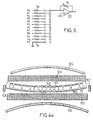
- connection matrix advantageously comprising a battery of twelve preamplifiers in parallel, denoted A 0 to A 11 , each adjustable gain preamplifier being connected via a connection matrix as shown in FIG. 2, to the four summing circuits, denoted 2 1 to 2 4 .
- the channel formed by the preamplifier A 11 can be a free channel, this for convenience being provided and which can then be connected to the reference voltage of the device.
- Each summing circuit 2 1 to 2 4 can be constituted, as shown in FIG.
- each elementary acoustic antenna or aforementioned sub-antenna is further associated with a means of low pass, band pass or high pass frequency filtering depending on the rank of the aforementioned sub-antenna, the bands frequencies transmitted by each filter associated with a elementary acoustic antenna being offset so as to cover a resulting bandwidth covering frequencies for example between 25 Hz and 7500 Hz.
- the mode actual filtering procedure will be described later in the description.
- acoustic antenna object of the present invention, indicates that this, in order to obtain implementation costs as low as possible, uses transducers electro-acoustic consisting of capsules microphones of bare electret type in place of complete sensors usually comprising, in addition to the actual capsule or sensitive microphone element, protective shielding, fixing device and connection elements and a housing for power supply electric.
- the aerial 1 or part of a cylindrical surface is formed by a frame, denoted 10, of substantially rectangular shape made of plastic material.
- This frame 10 is provided with spacers 100 and facing teeth 101, 102 formed in the plane of the frame 10 previously mentioned.
- Two opposite teeth form a housing intended to receive an electro-acoustic transducer, that is to say the microphone capsules M 0 to M 8 previously mentioned in the description.
- the frame 10 is bent so as to form the cylindrical surface part mentioned above.
- the acoustic antenna object of this invention, comprises, at level 1, a shield electromagnetic to ensure immunity of electro-acoustic transducers to noise or disturbance electro-magnetic.
- the shielding electro-magnetic consists of a metal grid, in fact by two metal grids bearing the references 103 and 104, these grids covering the concave part and the convex part of the cylindrical surface part, i.e. finally the rectangular frame 10 previously mentioned, and of course, the electro-acoustic transducers when these have been placed in the planned accommodation and intended to receive them.
- the metal grid 103, 104 is electrically connected to the electrical potential of reference of electro-acoustic transducers.
- the assembly of the aerial 1 is carried out by means of four rods, also made of plastic, carrying the references 105, 106, 107 and 108, these rods in material plastic with a suitable shape to ensure the assembly of the frame 10, provided with its electro-acoustic transducers and electromagnetic shielding grids 103 and 104 overlapping, the rods then being fixed to the periphery of the frame 10 to form a compact unit.
- the said rods are fixed by screws for example to frame 10.
- the main role of the frame 10 is to maintain the electro-acoustic transducers M 0 to M 8 .
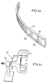
- the geometry of the latter therefore corresponds to that of the aerial 1 and of the antenna, the plastic mount constituting the frame therefore being curved in a semicircle as shown more significantly in FIG. 4b.
- the structure shown in Figure 4b for the frame 10 has the advantage of good solidity in the longitudinal direction and an acoustic transparency, the mechanical structure thus formed does not cause degradation of the acoustic characteristics of the electro-acoustic transducers inserted in the housings formed between two teeth 101, 102.
- Frame 10 can be made of PVC (polychloride vinyl), impact-resistant atactic polymer material and abrasion and whose machining is easy.
- the four rods previously mentioned 105, 106, 107, 108 thus surround frame 10 by strengthening the mechanical strength of this latest.
- Frame 10 is the part of the mechanical assembly which has the most effect on acoustic transparency. This transparency can only be obtained if frame 10 is the as hollowed out as possible so that the capsules are released from the material structure of the latter. Indeed, otherwise, the sound field disturbances modify the specific directional characteristics of electret capsules. This is the reason why the frame 10 as shown in Figures 4a and 4b shows the structure hollowed out between the teeth and the spacers previously mentioned. Laboratory tests have shown than electrets with a sensitivity diagram of cardioid type became omnidirectional in case, no precautions being taken, these were inserted in a full structure frame.
- the length L of the frame 10, that is to say the longitudinal dimension of it, corresponds to the opening of the acoustic antenna.
- the width 1 meets mechanical considerations such as maintaining electro-acoustic, acoustic transducers and aesthetic.
- the thickness h of the frame 10 is equal to that of the electret capsule inserted in each housing formed between two teeth 101, 102.
- Maintaining the microphone capsules can be ensured by truncated triangle shapes at the end of the teeth 101, 102, the truncation of each triangle can be rounded by drilling.
- the diameter of drilling is then chosen so as to allow attachment to force electret capsules in the housing as well formed at the end of the teeth 101, 102. This machining and the method of attachment of each capsule are identical for all capsules.
- the solidity of the frame 10 is obtained by the conservation of the material constituting the spacers 100 of width equal for example to 5 mm. These spacers forming stiffeners are four in number and can be advantageously located on the abscissa ⁇ 5 cm, ⁇ 10 cm on the semicircle taking as origin the position of the central electro-acoustic transducer M 0 . In the central part of the antenna and consequently of the frame 10, it is not necessary to provide a stiffener or spacers 100 because of the short distance between microphones and the allocation of these at high frequencies. Indeed, the directivity disturbances of the electro-acoustic transducers due to obstacles, are stronger at high frequencies than at low frequencies.
- the recesses can be made on one piece straight before bending, the radius of curvature of the frame 10 then being obtained by hot bending.
- the rods 105, 106, 107, 108 can be formed in a copolymer material called impact polystyrene (SB). Of U-shaped section, the rods are formed by the four aforementioned elements, which surround the frame 10 and are attached to it. The main role of the rushes is to reinforce the mechanical rigidity of the assembly.
- the rushes 105, 106, 107 and 108 can be produced by thermoforming, technique applicable to thermoplastics such as impact polystyrene, while allowing forming rods of small size but having good mechanical strength.
- electromagnetic shielding grids 103 and 104 it is indicated that these are made necessary due to lack of shielding specific to each electro-acoustic transducer used.
- the absence of an electromagnetic shielding has for effect of introducing harmful lines at 50 Hz and harmonics of this frequency in the signal spectrum of unshielded electro-acoustic antenna output.
- the the aforementioned electromagnetic shielding grids allow to suppress such a harmful phenomenon.
- the the aforementioned grids must be acoustically transparent, easy to implement and perfectly match the mechanical structure of the air 1.
- the two electro-magnetic shielding grids 103 and 104 are formed by two tinned metal grids surrounding frame 10 of aerial 1.
- the two grids above overlap at the ends of the frame 10 and the electrical mass of each electret capsule forming transducer electro-acoustic is connected to the aforementioned grids by a ground wire.
- Grids 103 and 104 are made of expanded metal micro-meshes of a material such as brass, of length 490 mm and 40 mm wide, and have openings in diamond shape of dimensions 1.45 x 0.25 mm. Their thickness is 0.2 mm and therefore has a fineness which allows to follow the shape of the mechanical structure of overhead 1, electrical contact being provided at the end of the last. Grid mesh dimensions above are entirely satisfactory to ensure a effective electromagnetic shielding.
- the metal grids forming the electromagnetic shielding previously cited also have a very good quality of acoustic transparency. This condition is checked due to the empty / full ratio of the grid, which is well above 50%.
- the aerial 1 can then be installed for example on the video monitor of a workstation thanks to a support 110, as shown in the above figure, which includes an air attachment claw 10, noted 111, the assembly being mounted on a ball joint 112 allowing the orientation of the aerial and in particular of the axis of symmetry of it towards the locution zone L.
- the claw 111 is formed by a double clamp which encloses the aerial 1 at the rushes.
- the ball 112 is formed by a ball lockable with screws, allowing orientation on demand. The fineness of the frame ensures acoustic transparency from the whole.
- FIG. 4d a view of the complete aerial 1, the capsules being put in place but the electro-magnetic shielding grid 104 being eliminated in order to show the interior aspect of the whole.
- the two most extreme electro-acoustic transducers, M 9 and M 10 these can be placed in a structure similar to the frame 10 shown in FIG. 4b but of greatly reduced dimensions since it suffices that the corresponding structure actually has a single pair of teeth 101, 102 to ensure the establishment of the electret capsule forming the electro-acoustic transducer. It is then indicated that the elementary aerials thus formed, for the electro-acoustic transducers M 9 and M 10 , can be placed on one or the sides of the video monitor of a multimedia work station for example, as will be described later in the description, the only condition to be observed being the distance condition D of the order of 30 cm with respect to the aerial 1. It is in fact indicated that the electro-acoustic transducers M 9 and M 10 are intended for low frequencies for which positioning errors are less critical.
- the pre-amplifiers A 0 to A 10 can be produced by operational amplifiers as already mentioned previously in the description.
- these pre-amplifiers could be the subject of a differential type mounting, each pre-amplifier having a gain adjustment making it possible to compensate for the differences in efficiency of the different electret capsules.
- This type of differential assembly will not be described in detail since it may correspond to a conventional type diagram normally used to supply and discriminate the analog sound signals delivered by an electret capsule normally used in the corresponding technique.
- each summing circuit 2 1 , 2 2 , 2 3 , 2 4 is followed for example in a block diagram by an analog-to-digital converter 3 1 , 3 2 , 3 3 , 3 4 and connected in cascade to each of these analog digital converters by a filter 4 1 , 4 2 , 4 3 , 4 4 .
- the output of each filter is then connected to the summing circuit 5 making it possible to deliver the resulting analog sound signal SUL.
- each sub-antenna SA 1 , SA 2 , SA 3 , SA 4 are each delivered to an analog low-pass filter with cut-off frequency 7 kHz, each of the analog filters delivering a corresponding filtered signal, noted SA 1 * , SA 2 * , SA 3 * , SA 4 * .
- the analog-to-digital conversion of the above-mentioned filtered signals is carried out by means of dual-channel analog digital converters, marketed for example under the brand CRYSTAL reference 5356, these two-channel converters, two in number and bearing, by similarity to FIG.
- a time multiplexing circuit is provided, which receives the aforementioned signals delivered by the two analog digital converters 3 1,2 , respectively 3 3,4 , this multiplexing circuit delivering the various aforementioned frames to a signal processor of the TMS 320C50 type marketed. by TEXAS INSTRUMENTS.
- An oscillator at 49.152 MHz makes it possible to control a time base making it possible to deliver signals of sampling frequency to the aforementioned analog digital converters.
- a digital analog converter circuit of the type marketed for example under the brand CRYSTAL reference 4328 makes it possible to restore the signal in analog form, the summation being carried out beforehand within the signal processor.
- the analog-to-digital conversion carried out by the converters 3 1,2 and 3 3,4 is carried out at the same time from the same sampling clock signal CLK delivered by the time base in order to respect the perfect synchronism between the different sub- antennas.
- Each of the aforementioned analog digital converters 3 1,2 respectively 3 3,4 delivers the digitized data on an independent serial train.
- the processing processor digital allows you to perform the various operations of digital filtering on multiplexing on trains digital data each corresponding to the data and therefore to the signals delivered by each of the sub-antennas.
- the multiplexing is thus carried out without shifting the sampling clock signals through realization a specific time base with a tracking system start of frame, in order to find the related signals to each channel in the corresponding order for the same given sampling instant.
- the operation of the assembly is as follows: following the appearance of the FSR signal, the recording of each train corresponding to a sampling instant is done at the signal processor level, then on interruption caused at the signal processor level, the filtering processing is carried out by the latter, the Iack signal representing a response to this interrupt and therefore the filtering performed for each of the data streams represented by the signal Drr.
- the signals delivered by the signal processor, in which a summons has been performed, are then subjected to digital conversion analog.
- the filtering performed by the signal processor is realized in the form digital rather than analog filtering for design flexibility reasons.
- the sum of the filters applied to each of the corresponding signals delivered by the sub-antennas is equal to unity for all frequencies, these filters should not introduce any degradation of the signal.
- These filters are also limited in size in order to maintain a reasonable complexity of calculations.
- Filters can be designed according to different criteria.
- each filter thus produced by filtering by the signal processor is a bandpass type filter classic whose cutoff frequencies are chosen so that each sub-antenna is limited to its band of natural frequencies.
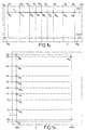
- Figure 6a presents the responses in frequencies of the filters thus retained.
- RIF finite impulse response filters having by example 31 coefficients.
- These filters are then synthesized using a standard filter design procedure RIF.
- An iterative algorithm ensures that the sum of the filters is equal to unity for all frequencies, the function of transfer of each of the filters being well limited to its own frequency band.
- a second approach consists in implementing filters so as to minimize a determined criterion, which can for example correspond to minimizing the energy received outside the speaker's area.
- a determined criterion which can for example correspond to minimizing the energy received outside the speaker's area.
- Figure 6b shows the frequency responses of the filters resulting from the above optimization.
- the filters thus produced make it possible to minimize the energy received from directions external to the useful opening area defined as an area of ⁇ 60 ° in the plane containing the electro-acoustic transducers M 0 to M 8 .
- These filters have a length of 128 coefficients.
- the second embodiment as shown in Figure 6b increases the directivity of the antenna under the conditions previously indicated.
- the aerial 1 is placed laterally to the video display monitor on one of the sides thereof, the aerial 1 then being fixed on the side of the latter at by means of a suction cup system for example or the like.
- the electro-acoustic transducers M 9 and M 10 can on the contrary be placed symmetrically with respect to the plane of symmetry P of the aerial 1 on two generating lines G 10 , G 9 of the convex surface S.
- an electro-acoustic transducer M 11 belonging to the first sub-antenna, band 1 in FIG. 6a can be placed at the top of the video display monitor, midway between the aerial 1 and the electro-acoustic transducers M 9 , M 10 in order to improve the overall performance of the antenna.
- the acoustic antenna object of the present invention is particularly advantageous insofar as it allows a selective sound which favors the user by greatly reducing noise-related damage ambient and room effect. Compared to a microphone unique, current classic solution, gain in selectivity spatial is important as well as noise reduction internal to the sensor.
- the space requirements of the air 1 are not excessive compared to the solution of using a single microphone.
- analog-to-digital conversion and the digital processing can be easily integrated into an echo control and coding system.
Landscapes
- Health & Medical Sciences (AREA)
- Otolaryngology (AREA)
- Physics & Mathematics (AREA)
- Engineering & Computer Science (AREA)
- Acoustics & Sound (AREA)
- Signal Processing (AREA)
- General Health & Medical Sciences (AREA)
- Obtaining Desirable Characteristics In Audible-Bandwidth Transducers (AREA)
- Electrostatic, Electromagnetic, Magneto- Strictive, And Variable-Resistance Transducers (AREA)
- Support Of Aerials (AREA)
Claims (8)
- System zur selektiven Schallaufnahme in einer reflexions- und rauschbehafteten Umgebung, umfassend eine Mehrzahl elektroakustischer Wandler (M0 bis M10), welche zur Aufnahme gleichphasiger Nutzschallsignale bestimmt sind, die von ein und derselben Sprachnutzzone (L) kommen, wobei die Nutzschallsignale gleichphasig summiert werden und solche Schallsignale, die von anderen Zonen als der Nutzzone (L) stammen, phaseninkohärent summiert werden, um die von der Sprachnutzzone kommenden Schallsignale auszulesen, dadurch gekennzeichnet, dass die elektroakustischen Wandler (M0 bis M10) im Wesentlichen unidirektionaler Art sind, wobei das System in Kombination umfasst:einen Antennenkörper (1), welcher von einem konkaven Zylinderflächenstück (S) gebildet ist, wobei die Konkavität der Zylinderfläche zur Sprachnutzzone (L) hin gerichtet ist, wobei die Mehrzahl von elektroakustischen Wandlern (M0 bis M10) längs der Zylinderfläche (S) verteilt und dieser benachbart ist, wobei jeder elektroakustische Wandler (M0 bis M10) zu der Sprachnutzzone (L) hin gerichtet ist und ein analoges Schallsignal (S0 bis S10) bereitstellt, wobei die Anordnung aus Antennenkörper (1) und elektroakustischen Wandlern (M0 bis M10) eine akustische Antenne bildet, wobei die elektroakustischen Wandler (M0 bis M10) auf eine erste (M0 bis M8) und eine zweite (M9, M10) Gruppe verteilt sind, wobei die elektroakustischen Wandler der ersten Gruppe (M0 bis M8) von ungerader Anzahl sind und längs einer zu einer Leitkurve des Zylinderstücks parallelen Linie der gekrümmten Fläche ausgerichtet und symmetrisch bezüglich einer eine Erzeugende der Zylinderfläche (S) sowie einen mittigen elektroakustischen Wandler (M0) enthaltenden Symmetrieebene angeordnet sind, wobei die elektroakustischen Wandler der zweiten Gruppe (M9, M10) längs einer oder mehrerer Leitkurven der konkaven Zylinderfläche (S) verteilt sind,Summationsmittel (21, 22, 23, 24) zur partiellen Summierung mehrerer der von den elektroakustischen Wandlern (M0 bis M10) bereitgestellten analogen Schallsignale gemäß einer vorbestimmten Anordnung, was es erlaubt, mit den elektroakustischen Wandlern eine Mehrzahl akustischer Elementarantennen zu bilden, welche jeweils ein resultierendes analoges Elementarschallsignal (SA1, SA2, SA3, SA4) bereitstellen,Filter- und Summationsmittel (41, 42, 43, 44 und 5) zur Filterung und Summierung der resultierenden analogen Elementarschallsignale, um ein resultierendes analoges Schallsignal (SUL) zu erzeugen, welches für das von der Sprachnutzzone (L) kommende Schallsignal repräsentativ ist.
- System zur selektiven Schallaufnahme nach Anspruch 1, dadurch gekennzeichnet, dass die elektroakustischen Wandler der zweiten Gruppe (M9, M10) symmetrisch bezüglich der Symmetrieebene verteilt sind.
- System zur selektiven Schallaufnahme nach Anspruch 1 oder 2, dadurch gekennzeichnet, dass ferner jeder akustischen Elementarantenne ein Filtermittel (41, 42, 43, 44) zur Tiefpass-, Bandpass- oder Hochpassfilterung zugeordnet ist, wobei die Frequenzbänder, die von den jeweils einer akustischen Elementarantenne zugeordneten Filtern durchgelassen werden, derart versetzt sind, dass ein resultierendes Durchlassband abgedeckt ist, welches die Frequenzen zwischen 25 Hz und 7500 Hz abdeckt.
- System zur selektiven Schallaufnahme nach einem der Ansprüche 1 bis 3, dadurch gekennzeichnet, dass das Zylinderflächenstück (S) von einem im Wesentlichen rechteckförmigen Rahmen (10) aus Kunststoffmaterial gebildet ist, wobei der Rahmen (10) mit Stegen (100) und einander gegenüberliegenden Zähnen (101, 102) ausgeführt ist, welche in der Ebene des Rahmens (10) gebildet sind, wobei zwei einander gegenüberliegende Zähne (101, 102) eine Aufnahme bilden, welche zur Unterbringung eines elektroakustischen Wandlers bestimmt ist, wobei der Rahmen (10) zur Bildung des Zylinderflächenstücks (S) gekrümmt ist.
- System nach Anspruch 1, dadurch gekennzeichnet, dass die akustische Antenne ferner eine elektromagnetische Abschirmung (103, 104) aufweist, welche es erlaubt, die elektroakustischen Wandler von elektromagnetischen Parasitär- oder Störeinflüssen freizuhalten.
- System nach den Ansprüchen 4 und 5, dadurch gekennzeichnet, dass die elektromagnetische Abschirmung von einem Metallgitter (103, 104) gebildet ist, welches den konkaven Teil und den konvexen Teil des Zylinderflächenstücks (S) sowie die elektroakustischen Wandler überdeckt, wobei das Metallgitter (103, 104) mit einem elektrischen Bezugspotenzial der elektroakustischen Wandler elektrisch verbunden ist.
- System nach Anspruch 1, dadurch gekennzeichnet, dass die Wandler der zweiten (M9, M10) Gruppe an einer von der Zylinderfläche (S) unabhängigen mechanischen Struktur angeordnet sind.
- Verwendung eines Systems zur selektiven Schallaufnahme nach einem der Ansprüche 1 bis 7 mit einer Multimedia-Arbeitsstation, wobei der Antennenkörper (1) und die elektroakustischen Wandler der ersten Gruppe (M0 bis M8) einer Seite des Bildanzeigemonitors der Arbeitsstation benachbart angeordnet sind, wobei die Wandler der zweiten Gruppe (M9, M10) auf mindestens einer Leitkurve (G9, G10) der konkaven Zylinderfläche (S) angeordnet sind.
Applications Claiming Priority (2)
| Application Number | Priority Date | Filing Date | Title |
|---|---|---|---|
| FR9408809 | 1994-07-15 | ||
| FR9408809A FR2722637B1 (fr) | 1994-07-15 | 1994-07-15 | Systeme de prise de son selective pour environnement reverberant et bruyant |
Publications (2)
| Publication Number | Publication Date |
|---|---|
| EP0692923A1 EP0692923A1 (de) | 1996-01-17 |
| EP0692923B1 true EP0692923B1 (de) | 2001-11-07 |
Family
ID=9465438
Family Applications (1)
| Application Number | Title | Priority Date | Filing Date |
|---|---|---|---|
| EP95401673A Expired - Lifetime EP0692923B1 (de) | 1994-07-15 | 1995-07-12 | Selektive Schallaufnahmevorrichtung für reflektierende und geräuschvolle Umgebung |
Country Status (4)
| Country | Link |
|---|---|
| US (1) | US5684882A (de) |
| EP (1) | EP0692923B1 (de) |
| DE (1) | DE69523676T2 (de) |
| FR (1) | FR2722637B1 (de) |
Families Citing this family (13)
| Publication number | Priority date | Publication date | Assignee | Title |
|---|---|---|---|---|
| FR2742960B1 (fr) * | 1995-12-22 | 1998-02-20 | Mahieux Yannick | Antenne acoustique pour station de travail informatique |
| DE59801138D1 (de) * | 1997-04-10 | 2001-09-06 | Interkom Electronic Kock & Mre | Schallaufnahmeeinrichtung, insbesondere für eine sprechstelle |
| US6603861B1 (en) | 1997-08-20 | 2003-08-05 | Phonak Ag | Method for electronically beam forming acoustical signals and acoustical sensor apparatus |
| EP1035752A1 (de) | 1999-03-05 | 2000-09-13 | Phonak Ag | Verfahren zur Formgebung der Empfangsverstärkungsraumcharakteristik einer Umwandleranordnung und Umwandleranordnung |
| US6353578B1 (en) | 1999-05-27 | 2002-03-05 | Ronald A. Wagstaff | Phase alignment for vector and coherent signal processing |
| DE10119266A1 (de) * | 2001-04-20 | 2002-10-31 | Infineon Technologies Ag | Programmgesteuerte Einheit |
| US7068796B2 (en) * | 2001-07-31 | 2006-06-27 | Moorer James A | Ultra-directional microphones |
| FR2831763B1 (fr) * | 2001-10-26 | 2004-03-19 | Get Enst | Dispositif de saisie et restitution du son utilisant plusieurs capteurs |
| US20040114772A1 (en) * | 2002-03-21 | 2004-06-17 | David Zlotnick | Method and system for transmitting and/or receiving audio signals with a desired direction |
| KR100677613B1 (ko) * | 2005-09-09 | 2007-02-02 | 삼성전자주식회사 | 멀티미디어 기기의 동작을 제어하는 방법 및 그 장치 |
| WO2011014389A2 (en) * | 2009-07-31 | 2011-02-03 | Halliburton Energy Services, Inc. | Exploitation of sea floor rig structures to enhance measurement while drilling telemetry data |
| US8886541B2 (en) * | 2010-02-04 | 2014-11-11 | Sony Corporation | Remote controller with position actuatated voice transmission |
| US10516962B2 (en) | 2017-07-06 | 2019-12-24 | Huddly As | Multi-channel binaural recording and dynamic playback |
Family Cites Families (7)
| Publication number | Priority date | Publication date | Assignee | Title |
|---|---|---|---|---|
| US4310730A (en) * | 1979-07-25 | 1982-01-12 | Aaroe Kenneth T | Shielded piezoelectric acoustic pickup for mounting on musical instrument sounding boards |
| JPS5939198A (ja) * | 1982-08-27 | 1984-03-03 | Victor Co Of Japan Ltd | マイクロホン装置 |
| FR2559325B1 (fr) * | 1984-02-06 | 1986-08-22 | Renault | Appareillage permettant de capter et de transmettre au loin la parole d'une personne placee dans un milieu perturbe afin d'effectuer un traitement de cette parole |
| JPS6223300A (ja) * | 1985-07-23 | 1987-01-31 | Victor Co Of Japan Ltd | 指向性マイクロホン装置 |
| US4653102A (en) * | 1985-11-05 | 1987-03-24 | Position Orientation Systems | Directional microphone system |
| JPS62135020A (ja) * | 1985-12-06 | 1987-06-18 | Nec Corp | 雑音消去装置 |
| JPH0728470B2 (ja) * | 1989-02-03 | 1995-03-29 | 松下電器産業株式会社 | アレイマイクロホン |
-
1994
- 1994-07-15 FR FR9408809A patent/FR2722637B1/fr not_active Expired - Fee Related
-
1995
- 1995-07-12 DE DE69523676T patent/DE69523676T2/de not_active Expired - Lifetime
- 1995-07-12 EP EP95401673A patent/EP0692923B1/de not_active Expired - Lifetime
- 1995-07-14 US US08/502,695 patent/US5684882A/en not_active Expired - Lifetime
Also Published As
| Publication number | Publication date |
|---|---|
| EP0692923A1 (de) | 1996-01-17 |
| US5684882A (en) | 1997-11-04 |
| FR2722637A1 (fr) | 1996-01-19 |
| FR2722637B1 (fr) | 1996-09-20 |
| DE69523676D1 (de) | 2001-12-13 |
| DE69523676T2 (de) | 2002-07-25 |
Similar Documents
| Publication | Publication Date | Title |
|---|---|---|
| US8213634B1 (en) | Modular and scalable directional audio array with novel filtering | |
| CN112335261B (zh) | 图案形成麦克风阵列 | |
| EP0333581B1 (de) | Einrichtung zur Echokompensation mit Filterung in Frequenzteilbändern | |
| EP2530673B1 (de) | Audiogerät mit Rauschunterdrückung in einem Sprachsignal unter Verwendung von einem Filter mit fraktionaler Verzögerung | |
| EP2518724B1 (de) | Kombinierte Audioeinheit bestehend aus Mikrofon und Kopfhörer, die Mittel zur Geräuschdämpfung eines nahen Wortsignals umfasst, insbesondere für eine telefonische Freisprechanlage | |
| EP0606387B1 (de) | System zur tonaufnahme sowie gerät zur tonaufnahme und -wiedergabe | |
| FR2722637A1 (fr) | Systeme de prise de son selective pour environnement reverberant et bruyant | |
| EP0781070B1 (de) | Akustische Antenne für Computerarbeitsplatz | |
| FR2919454A1 (fr) | Systeme de reproduction sonore a enceinte a events. | |
| FR2992459A1 (fr) | Procede de debruitage d'un signal acoustique pour un dispositif audio multi-microphone operant dans un milieu bruite. | |
| EP1230784A1 (de) | Verfahren und vorrichtung zur echoverminderung | |
| EP1652406B1 (de) | System und verfahren zur bestimmung einer repräsentation eines akustischen feldes | |
| EP0061812A1 (de) | Anordnung von akustischen Wandlern und Verwendung dieser Anordnung in einem Fernsprecher mit Freisprechanlage | |
| FR2764469A1 (fr) | Procede et dispositif de traitement optimise d'un signal perturbateur lors d'une prise de son | |
| US8275147B2 (en) | Selective shaping of communication signals | |
| EP0663136B1 (de) | Elektroakustischer wandler mit schallabstrahlendem volumen | |
| FR2559984A1 (fr) | Microphone auriculaire de contact | |
| Schobben et al. | Transparent communication | |
| JP6031364B2 (ja) | 収音装置及び再生装置 | |
| FR2617660A1 (fr) | Dispositif de prise et de restitution du son, notamment pour audio-conferences | |
| EP1211668A1 (de) | Aktiver akustischer Reflektor | |
| FR2924523A1 (fr) | Etui pour microphone unidirectionnel et appareil electronique comportant un tel etui | |
| EP0710427B1 (de) | Schallaufnahme-und-wiedergabegerät, und seine anwendung für audiokonferenzen | |
| EP0613319B1 (de) | Mehrmikrofon-Schallaufnahmevorrichtung und dazugehörende Signalverarbeitungsvorrichtung | |
| FR2559325A1 (fr) | Appareillage permettant de capter et de transmettre au loin la parole d'une personne placee dans un milieu perturbe afin d'effectuer un traitement de cette parole |
Legal Events
| Date | Code | Title | Description |
|---|---|---|---|
| PUAI | Public reference made under article 153(3) epc to a published international application that has entered the european phase |
Free format text: ORIGINAL CODE: 0009012 |
|
| AK | Designated contracting states |
Kind code of ref document: A1 Designated state(s): DE GB IT NL SE |
|
| 17P | Request for examination filed |
Effective date: 19960102 |
|
| 17Q | First examination report despatched |
Effective date: 19991111 |
|
| GRAG | Despatch of communication of intention to grant |
Free format text: ORIGINAL CODE: EPIDOS AGRA |
|
| GRAG | Despatch of communication of intention to grant |
Free format text: ORIGINAL CODE: EPIDOS AGRA |
|
| GRAH | Despatch of communication of intention to grant a patent |
Free format text: ORIGINAL CODE: EPIDOS IGRA |
|
| GRAH | Despatch of communication of intention to grant a patent |
Free format text: ORIGINAL CODE: EPIDOS IGRA |
|
| GRAA | (expected) grant |
Free format text: ORIGINAL CODE: 0009210 |
|
| AK | Designated contracting states |
Kind code of ref document: B1 Designated state(s): DE GB IT NL SE |
|
| REF | Corresponds to: |
Ref document number: 69523676 Country of ref document: DE Date of ref document: 20011213 |
|
| REG | Reference to a national code |
Ref country code: GB Ref legal event code: IF02 |
|
| GBT | Gb: translation of ep patent filed (gb section 77(6)(a)/1977) |
Effective date: 20020123 |
|
| PLBE | No opposition filed within time limit |
Free format text: ORIGINAL CODE: 0009261 |
|
| STAA | Information on the status of an ep patent application or granted ep patent |
Free format text: STATUS: NO OPPOSITION FILED WITHIN TIME LIMIT |
|
| 26N | No opposition filed | ||
| PGFP | Annual fee paid to national office [announced via postgrant information from national office to epo] |
Ref country code: SE Payment date: 20070625 Year of fee payment: 13 |
|
| PGFP | Annual fee paid to national office [announced via postgrant information from national office to epo] |
Ref country code: NL Payment date: 20070627 Year of fee payment: 13 |
|
| PGFP | Annual fee paid to national office [announced via postgrant information from national office to epo] |
Ref country code: IT Payment date: 20080717 Year of fee payment: 14 |
|
| EUG | Se: european patent has lapsed | ||
| NLV4 | Nl: lapsed or anulled due to non-payment of the annual fee |
Effective date: 20090201 |
|
| PG25 | Lapsed in a contracting state [announced via postgrant information from national office to epo] |
Ref country code: NL Free format text: LAPSE BECAUSE OF NON-PAYMENT OF DUE FEES Effective date: 20090201 |
|
| REG | Reference to a national code |
Ref country code: GB Ref legal event code: 732E Free format text: REGISTERED BETWEEN 20090924 AND 20090930 |
|
| PG25 | Lapsed in a contracting state [announced via postgrant information from national office to epo] |
Ref country code: SE Free format text: LAPSE BECAUSE OF NON-PAYMENT OF DUE FEES Effective date: 20080713 |
|
| PG25 | Lapsed in a contracting state [announced via postgrant information from national office to epo] |
Ref country code: IT Free format text: LAPSE BECAUSE OF NON-PAYMENT OF DUE FEES Effective date: 20090712 |
|
| PGFP | Annual fee paid to national office [announced via postgrant information from national office to epo] |
Ref country code: DE Payment date: 20110729 Year of fee payment: 17 |
|
| PG25 | Lapsed in a contracting state [announced via postgrant information from national office to epo] |
Ref country code: DE Free format text: LAPSE BECAUSE OF NON-PAYMENT OF DUE FEES Effective date: 20130201 |
|
| PGFP | Annual fee paid to national office [announced via postgrant information from national office to epo] |
Ref country code: GB Payment date: 20130624 Year of fee payment: 19 |
|
| REG | Reference to a national code |
Ref country code: DE Ref legal event code: R119 Ref document number: 69523676 Country of ref document: DE Effective date: 20130201 |
|
| GBPC | Gb: european patent ceased through non-payment of renewal fee |
Effective date: 20140712 |
|
| PG25 | Lapsed in a contracting state [announced via postgrant information from national office to epo] |
Ref country code: GB Free format text: LAPSE BECAUSE OF NON-PAYMENT OF DUE FEES Effective date: 20140712 |