EP0693028B1 - Maschine zum automatischen zusammenbringen von verpackungsstapeln, die kupferschichten enthalten um plastiklaminate aus serpentinenförmig angeordneten bändern herzustellen - Google Patents
Maschine zum automatischen zusammenbringen von verpackungsstapeln, die kupferschichten enthalten um plastiklaminate aus serpentinenförmig angeordneten bändern herzustellen Download PDFInfo
- Publication number
- EP0693028B1 EP0693028B1 EP93924788A EP93924788A EP0693028B1 EP 0693028 B1 EP0693028 B1 EP 0693028B1 EP 93924788 A EP93924788 A EP 93924788A EP 93924788 A EP93924788 A EP 93924788A EP 0693028 B1 EP0693028 B1 EP 0693028B1
- Authority
- EP
- European Patent Office
- Prior art keywords
- bands
- pile
- work table
- metal
- packages
- Prior art date
- Legal status (The legal status is an assumption and is not a legal conclusion. Google has not performed a legal analysis and makes no representation as to the accuracy of the status listed.)
- Expired - Lifetime
Links
- RYGMFSIKBFXOCR-UHFFFAOYSA-N Copper Chemical compound [Cu] RYGMFSIKBFXOCR-UHFFFAOYSA-N 0.000 title claims abstract description 49
- 229910052802 copper Inorganic materials 0.000 title claims abstract description 47
- 239000010949 copper Substances 0.000 title claims abstract description 47
- 239000002650 laminated plastic Substances 0.000 title claims abstract description 21
- 239000002184 metal Substances 0.000 claims description 61
- 229910052751 metal Inorganic materials 0.000 claims description 61
- 230000000087 stabilizing effect Effects 0.000 claims description 18
- 230000015572 biosynthetic process Effects 0.000 claims description 16
- 238000000034 method Methods 0.000 claims description 9
- WYTGDNHDOZPMIW-RCBQFDQVSA-N alstonine Natural products C1=CC2=C3C=CC=CC3=NC2=C2N1C[C@H]1[C@H](C)OC=C(C(=O)OC)[C@H]1C2 WYTGDNHDOZPMIW-RCBQFDQVSA-N 0.000 claims description 5
- 238000007599 discharging Methods 0.000 claims description 3
- 230000000284 resting effect Effects 0.000 claims 1
- 230000000630 rising effect Effects 0.000 claims 1
- 238000004804 winding Methods 0.000 claims 1
- 239000011810 insulating material Substances 0.000 abstract description 5
- 229910000831 Steel Inorganic materials 0.000 description 6
- 239000010959 steel Substances 0.000 description 6
- 239000000463 material Substances 0.000 description 4
- 238000004519 manufacturing process Methods 0.000 description 2
- 239000003381 stabilizer Substances 0.000 description 2
- 238000010276 construction Methods 0.000 description 1
- 230000005611 electricity Effects 0.000 description 1
- 238000010438 heat treatment Methods 0.000 description 1
- 239000000203 mixture Substances 0.000 description 1
- 238000003825 pressing Methods 0.000 description 1
Images








Classifications
-
- B—PERFORMING OPERATIONS; TRANSPORTING
- B32—LAYERED PRODUCTS
- B32B—LAYERED PRODUCTS, i.e. PRODUCTS BUILT-UP OF STRATA OF FLAT OR NON-FLAT, e.g. CELLULAR OR HONEYCOMB, FORM
- B32B37/00—Methods or apparatus for laminating, e.g. by curing or by ultrasonic bonding
- B32B37/10—Methods or apparatus for laminating, e.g. by curing or by ultrasonic bonding characterised by the pressing technique, e.g. using action of vacuum or fluid pressure
- B32B37/1045—Intermittent pressing, e.g. by oscillating or reciprocating motion of the pressing means
-
- B—PERFORMING OPERATIONS; TRANSPORTING
- B32—LAYERED PRODUCTS
- B32B—LAYERED PRODUCTS, i.e. PRODUCTS BUILT-UP OF STRATA OF FLAT OR NON-FLAT, e.g. CELLULAR OR HONEYCOMB, FORM
- B32B38/00—Ancillary operations in connection with laminating processes
- B32B38/18—Handling of layers or the laminate
- B32B38/1808—Handling of layers or the laminate characterised by the laying up of the layers
-
- B—PERFORMING OPERATIONS; TRANSPORTING
- B32—LAYERED PRODUCTS
- B32B—LAYERED PRODUCTS, i.e. PRODUCTS BUILT-UP OF STRATA OF FLAT OR NON-FLAT, e.g. CELLULAR OR HONEYCOMB, FORM
- B32B2457/00—Electrical equipment
- B32B2457/08—PCBs, i.e. printed circuit boards
-
- Y—GENERAL TAGGING OF NEW TECHNOLOGICAL DEVELOPMENTS; GENERAL TAGGING OF CROSS-SECTIONAL TECHNOLOGIES SPANNING OVER SEVERAL SECTIONS OF THE IPC; TECHNICAL SUBJECTS COVERED BY FORMER USPC CROSS-REFERENCE ART COLLECTIONS [XRACs] AND DIGESTS
- Y10—TECHNICAL SUBJECTS COVERED BY FORMER USPC
- Y10T—TECHNICAL SUBJECTS COVERED BY FORMER US CLASSIFICATION
- Y10T156/00—Adhesive bonding and miscellaneous chemical manufacture
- Y10T156/10—Methods of surface bonding and/or assembly therefor
- Y10T156/1002—Methods of surface bonding and/or assembly therefor with permanent bending or reshaping or surface deformation of self sustaining lamina
- Y10T156/1007—Running or continuous length work
- Y10T156/1015—Folding
-
- Y—GENERAL TAGGING OF NEW TECHNOLOGICAL DEVELOPMENTS; GENERAL TAGGING OF CROSS-SECTIONAL TECHNOLOGIES SPANNING OVER SEVERAL SECTIONS OF THE IPC; TECHNICAL SUBJECTS COVERED BY FORMER USPC CROSS-REFERENCE ART COLLECTIONS [XRACs] AND DIGESTS
- Y10—TECHNICAL SUBJECTS COVERED BY FORMER USPC
- Y10T—TECHNICAL SUBJECTS COVERED BY FORMER US CLASSIFICATION
- Y10T156/00—Adhesive bonding and miscellaneous chemical manufacture
- Y10T156/10—Methods of surface bonding and/or assembly therefor
- Y10T156/1002—Methods of surface bonding and/or assembly therefor with permanent bending or reshaping or surface deformation of self sustaining lamina
- Y10T156/1043—Subsequent to assembly
- Y10T156/1044—Subsequent to assembly of parallel stacked sheets only
- Y10T156/1046—Bending of one lamina only
-
- Y—GENERAL TAGGING OF NEW TECHNOLOGICAL DEVELOPMENTS; GENERAL TAGGING OF CROSS-SECTIONAL TECHNOLOGIES SPANNING OVER SEVERAL SECTIONS OF THE IPC; TECHNICAL SUBJECTS COVERED BY FORMER USPC CROSS-REFERENCE ART COLLECTIONS [XRACs] AND DIGESTS
- Y10—TECHNICAL SUBJECTS COVERED BY FORMER USPC
- Y10T—TECHNICAL SUBJECTS COVERED BY FORMER US CLASSIFICATION
- Y10T156/00—Adhesive bonding and miscellaneous chemical manufacture
- Y10T156/10—Methods of surface bonding and/or assembly therefor
- Y10T156/1002—Methods of surface bonding and/or assembly therefor with permanent bending or reshaping or surface deformation of self sustaining lamina
- Y10T156/1043—Subsequent to assembly
- Y10T156/1049—Folding only
-
- Y—GENERAL TAGGING OF NEW TECHNOLOGICAL DEVELOPMENTS; GENERAL TAGGING OF CROSS-SECTIONAL TECHNOLOGIES SPANNING OVER SEVERAL SECTIONS OF THE IPC; TECHNICAL SUBJECTS COVERED BY FORMER USPC CROSS-REFERENCE ART COLLECTIONS [XRACs] AND DIGESTS
- Y10—TECHNICAL SUBJECTS COVERED BY FORMER USPC
- Y10T—TECHNICAL SUBJECTS COVERED BY FORMER US CLASSIFICATION
- Y10T156/00—Adhesive bonding and miscellaneous chemical manufacture
- Y10T156/10—Methods of surface bonding and/or assembly therefor
- Y10T156/1002—Methods of surface bonding and/or assembly therefor with permanent bending or reshaping or surface deformation of self sustaining lamina
- Y10T156/1051—Methods of surface bonding and/or assembly therefor with permanent bending or reshaping or surface deformation of self sustaining lamina by folding
-
- Y—GENERAL TAGGING OF NEW TECHNOLOGICAL DEVELOPMENTS; GENERAL TAGGING OF CROSS-SECTIONAL TECHNOLOGIES SPANNING OVER SEVERAL SECTIONS OF THE IPC; TECHNICAL SUBJECTS COVERED BY FORMER USPC CROSS-REFERENCE ART COLLECTIONS [XRACs] AND DIGESTS
- Y10—TECHNICAL SUBJECTS COVERED BY FORMER USPC
- Y10T—TECHNICAL SUBJECTS COVERED BY FORMER US CLASSIFICATION
- Y10T428/00—Stock material or miscellaneous articles
- Y10T428/24—Structurally defined web or sheet [e.g., overall dimension, etc.]
- Y10T428/2419—Fold at edge
- Y10T428/24215—Acute or reverse fold of exterior component
- Y10T428/24231—At opposed marginal edges
Definitions
- the pile of packages is gradually formed.
- the stabilizer unit comprises a pair of pressers each formed of a vertical frame transversal to the work surface.
- This sliding movement is worked by master cylinders or by some other driving means.
- sequences of work lead to formation of a pile of packages obtained by a succession of: insulating sheet, copper lamina, set of prepreg sheets, copper lamina, insulating sheet, intermediate sheet, insulating sheet, and so on.
- the pile of packages consists of: insulating band, metal band, set of sheets of prepreg, second metal band, second insulating band, intermediate metal band, insulating band, and so on until completion of the pile.
- Composition of the layers,consisting of pairs of metal bands associated to insulating bands not only makes possible endothermic heating of the piles of packages for plastic laminates, as disclosed in the above-mentioned patent application, but also a much more rational and efficient use of the automatic machine.
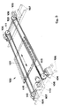
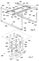
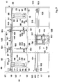
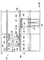
- Said machine has a cage-type parallelepiped structure 11 and includes the following main mechanical devices.
- the carriage 60 consists of two sides 61, 62 connected by the cross pieces 63-65.
- the shaft 96 is put into motion by the pins 89, 90 fixed to pinions 91, 92 pulled, by the continuous belt 94, by the pinion 93 mounted on the shaft of the electric ratio motor 95.
- the unit 100 that horizontally translates the work table 101 comprises the shafts 102, 103 that turn in the supports 104,105 fixed at the two ends of the machine on the pairs of cross bars 106, 107 of the structure 11.
- the hoisting unit 120 for the work table 101 comprises the hoisting means 121 which in turn comprises the plate 128 at the base fixed to the structure 11 of the machine by means of the cross bars 122.
- Said base plate 128 is connected to an upper plate 130 by four columns 125 to which are screwed the nuts 126, and carries in the centre a ratio motor 123 that works the vertical worm screw 124 turning in the bushing 127 of the upper plate 130.
- rods 158, 159 are fixed to the pistons of master cylinders 164, 165 fixed to the bars 152, 153.
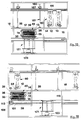
- the work table 101 is on the left at the discharge level 17, a pile of packages for plastic laminates assembled by the machine 10, having been taken of the table in that position in the preceding work sequence.
- the feeder carriages 60, 80 providing copper bands 12,13 and insulating bands 14,15 respectively from the reels 20, 21 and 22, 23, are in position at the longitudinal ends of the machine.
- the work table 101 is drawn along by the chains 115, 116 worked by the ratiomotor 113, to the position 101' in vertical alignment with the hoisting unit 121 and with the aperture 28 in the work surface 18.
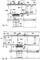
- Said hoister 121 worked by the ratio motor 123 carries the work table 101 onto the geometrical plane of the work surface 18, inside the aperture 28 (Fig. 7).
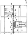
- the carriage 80 moves to the left hand end of the machine and the ends of the second copper band 13 and of the second insulating band 15 are placed, fed in by the second carriage 80 operated by the ratiomotor 95, guided by the idle roller 59, the intermediate sheet 30 being then laid on (Fig. 8).
- the insulating band 14, fed in by the reel 21, in practice is drawn along by friction against the copper band 12.
- the ratiomotor 95 pays out the copper band 13 from the reel 22 and the insulating band 11 from the reel 23.
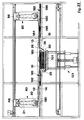
- the first carriage 60 returns to the left of the machine determining the second 180° bend by the first copper band 12 and by the first insulating band 14 around the intermediate sheet 31 held down by the presser 150 (Fig.12).
- serpentinewise arrangement of copper and insulating bands can obviously continue and other packages in the pile 45 be so formed.
- Said unit 180 comprises the longitudinal lateral C-shaped guides 190, 191 facing upwards.
- the work of these blades is substantially that done by the pressers 150, 151 in the stabilizing unit 140, their function being that of holding firm the components of the pile of packages, for making plastic laminates, while in the process of formation, and they therefore operate in the stages seen in Figs. 19-22 which correspond to those already illustrated in Figs. 9-12.
Landscapes
- Physics & Mathematics (AREA)
- Fluid Mechanics (AREA)
- Laminated Bodies (AREA)
- Veneer Processing And Manufacture Of Plywood (AREA)
- Moulding By Coating Moulds (AREA)
- Replacing, Conveying, And Pick-Finding For Filamentary Materials (AREA)
- Manufacturing Of Electrical Connectors (AREA)
- Casting Or Compression Moulding Of Plastics Or The Like (AREA)
- Wrappers (AREA)
- Basic Packing Technique (AREA)
Claims (9)
- Automatische Maschine (10, 110) für die Herstellung von Stapeln (45) von Paketen (38, 39) für die Erzeugung von Kunststofflaminaten mit Metallfolien, die aus Metall- und zwar insbesondere aus Kupferbändern (12, 13), hergestellt werden, die serpentinenartig jeweils zwischen die einzelnen Lagen (35, 36) aus vorimprägnierten und flachen Zwischenplatten (30-32) zwischen die Pakete (38, 39) geschichtet werden,
dadurch gekennzeichnet, daß sie eine längliche, längs verlaufende horizontale Arbeitsfläche (18) umfaßt, in der sich eine mittlere, rechteckige Öffnung (28) für die Aufnahme eines Arbeitstisches (101) befindet, auf dem ein Stapel Pakete (45) gebildet wird, eine Zufuhreinheit (50), die die Metallbänder (12, 13) abgibt, mit einer oder mehreren Schlitten (60, 80), von denen jeder mindestens eine Spule (20, 22) mit Metallband, insbesondere Kupferband, trägt und sich entlang parallel und längs verlaufender Führungen (52, 53) von einer Seite des Arbeitstischs (101) zur anderen verstellt, eine Einheit (120) zum Halten und Anheben des Arbeitstisch (101), eine Einheit (140, 180) für die Stabilisierung des Paketstapels für Laminate mit Hilfe von zwei Vorrichtungen (150, 151) (181, 182), die die Pakete halten, die nach Bedarf entlang längs verlaufender Führungen (142, 143) (190, 191) von den Leerlaufpositionen, von denen sich jeweils eine an jeder Seite des Arbeitstischs (101) befindet, zu der Position des Paketstapels (45) am Arbeitstisch (101) während einer Stufe des Arbeitsablaufs verfahren werden können, sowie eine elektronische Steuereinheit, die den Arbeitsablauf programmiert und die einzelnen Bewegungen synchronisiert, so daß bei der jeweiligen Vor- und Rückwärtsverstellung der Spulen (60, 80) von einer Seite zur anderen des Arbeitstischs (101) und bei Anordnung eines Endes von einem oder mehreren Metallbändern (12, 13) an besagtem Arbeitstisch (101) und bei Beginn jedes Arbeitsgangs, sowie bei Anordnung an besagten Enden, nach jedem wechselweisen Arbeitshub besagter Spulen (60, 80), einer Reihe von Platten aus vorimprägnierten (35, 36) und Zwischenplatten (30, 32), dieser Stapel (45) von Paketen progressiv aus den serpentinenartig verlegten Metallbändern (12, 13) hergestellt wird, die Biegungen von 180° in der einen und der anderen Richtung zwischen dem einen (38, 39) und dem nächsten Paket bilden, während der Arbeitstisch (101) durch Betätigung der Hebevorrichtung (120) im Lauf der Stapelbildung schrittweise heruntergefahren wird, damit seine obere Fläche praktisch auf gleicher Höhe mit der Arbeitsfläche (18) zu liegen kommt, wobei die Vorrichtung (150, 151) (181, 182) der Stabilisierungseinheit (140), (180), die sich an der Seite des Arbeitstisch (101) befindet, die der gegenüberliegt, nach der die Bänder (12-15) gerichtet sind, sich dann auf den wachsenden Stapel (15) zu bewegt und ihn festhält, während die Schlitten (60, 80) sich in Richtung der besagten Seite der Arbeitsfläche (18) bewegen, um die Bildung an den besagten Bändern (12-15) der Biegungen um 180° zu erleichtern, die zunächst in einer und dann in der anderen Richtung vollführt werden muß. - Automatische Maschine (10, 110) für die Herstellung von Stapeln laut Anspruch 1,
dadurch gekennzeichnet, daß an jedem Schlitten (60, 80) eine Spule (21, 23) mit Isolierband mit der Spule (20, 22) mit Metallband verbunden ist, so daß die Bänderserpentine, die sich zwischen einem Paket (38, 39) und dem nächsten windet, die Isolierbänder (14, 15) auf die Zwischenplatten (30, 32), und die Metallbänder (12, 13) auf die Reihen mit vorimprägnierten Platten (35, 36) passen läßt. - Automatische Maschine (10, 110) für die Herstellung von Stapeln laut Anspruch 1,
dadurch gekennzeichnet, daß an jedem Schlitten (60, 80) eine Spule mit Isolierband (21, 23) mit der Spule (20, 22) mit Metallband verbunden ist und dadurch, daß zwei Spulenträger-Schlitten (60, 80) vorhanden sind, die so beschaffen sind, daß bei Beginn des Arbeitsgangs mit den zwei Schlitten (60, 80) an einer Seite des Arbeitstischs (101) und bei Auflage auf diesen Tisch, in folgender Reihenfolge, der verbundenen Enden eines Isolierbands (14) und eines Metallbands (12), die verbundenen Enden eines zweiten Metallbands (13) und eines zweiten Isolierbands (15) die beiden Schlitten (60, 80) abwechselnd von einer Seite des Arbeitstischs (101) zur anderen bewegen und auf den wachsenden Stapel (45) bei jedem Hub des Schlittens (60, 80) und demzufolge bei jeder Biegung um 180°, die die Bänder vollführen, abwechselnd eine Zwischenplatte (30-32) und einen Satz vorimprägnierter Platten (35, 36) legen, wodurch der Paketstapel (45) schrittweise hergestellt wird. - Automatische Maschine (10, 101) für die Herstellung von Stapeln laut Anspruch 1,
dadurch gekennzeichnet, daß die Schlitten (60, 80) in der Zufuhreinheit (50) jeweils zwei Spulen tragen, und zwar eine untere (20, 22) mit Metallband (12, 13) und eine obere Spule (21, 23) mit Isolierband (14, 15), wobei deren Achsen parallel und orthogonal zur Richtung der Bewegung der Schlitten (60, 80) verlaufen, die beiden Spulen auf jedem Schlitten in die entgegengesetzten Richtungen gewickelt sind, das Isolierband (14, 15) um die Spule (20, 22) des Metallbands (12, 13) läuft, eine Losrolle (58, 59) am unteren Ende jedes Schlittens (60, 80), parallel zu den Spulen (20-23) an der der Abwicklungsrichtung der unteren Spulen (20,22) entgegengesetzten Richtung, und besagte untere Spulen (20, 22), die durch die Zugwirkung von zwei Wellen motorgetrieben werden, die Seite an Seite ein Paar (70, 71) (89, 90) bilden und innen an einer Seite (62, 81) des Schlittens (60, 80) vorstehen, und auf denen ein Ende der Welle (68, 96) der unteren Spule (20, 22) frei ruht, wobei diese Wellen (70, 71) (89, 90) durch eine stufenlose Kette (78, 94) gedreht werden, die durch einen elektrischen Getriebemotor (79, 95) gezogen wird, so daß durch Anlassen des besagten Getriebemotors (79, 95) die Spule (20, 22) mit dem Metallband das besagte Band (12, 13) zusammen mit dem Isolierband (14, 15) abwickelt, das mit Hilfe von Reibung vom ersten (12, 13) gezogen wird. - Automatische Maschine (10, 101) für die Herstellung von Stapeln laut Anspruch 1,
dadurch gekennzeichnet, daß die Stabilisiereinheit (140) ein Paar Preßvorrichtungen (150, 151) umfaßt, von denen jede aus einem senkrechten, quer zur Arbeitsflache verlaufenden Rahmen besteht, der eine obere Stange (152, 153) umfaßt, die eine untere waagerechte Stange (160, 161) mit Hilfe zweier senkrechter Stäbe (158, 159) trägt, die axial im Innern von zwei Ständern (154, 156) gleiten, die an dieser oberen Stange (152, 153) befestigt sind, die durch Hauptzylinder (164, 165) angetrieben wird, wobei der besagte Rahmen an Längsführungen (142, 143) über der Arbeitsfläche (18) aufgehängt ist und unter der Kontrolle von elektrischen Getriebemotoren (166, 167) steht, so daß bei Inbetriebsetzung der besagten Getriebemotoren (166, 167) und der besagten Hauptzylinder (164, 165) die beiden Preßvorrichtungen (150, 151) beliebig von ihren jeweiligen Leerlaufstellungen an der Seite des Arbeitstischs (101) in eine Arbeitsstellung oberhalb des besagten Tischs (101) verstellt werden können und dort bei gleichzeitiger Verwendung entsprechender elastischer Mittel (162, 163) einen ausreichenden Druck auf den in der Herstellung begriffenen Stapel (45) ausüben können, um die einzelnen Komponenten des Stapels (45) in der richtigen Stellung zu halten, insbesondere wenn die Schlitten (60, 80) von einer Seite des Arbeitstischs (101) zur anderen übergehen, damit die Bänder ihre Biegung um 180° vollführen können. - Automatische Maschine (10, 110) für die Herstellung von Stapeln laut Anspruch 1,
dadurch gekennzeichnet, daß die Stabilisiereinheit (180) zwei seitliche Langsführungen (190, 191) für zwei rechteckige waagerechte Klingen (181, 182) umfaßt, die wie gewünscht von einer Leerlaufstellung jeweils an der einen und der anderen Seite des Arbeitstischs (101) zu einer Stellung über dem besagten Arbeitstisch (101) gleiten, der durch Hauptzylinder (200, 201) oder andere Motorantriebe betätigt wird, so daß während der Bildung des Stapels (45) und gerade in dem Moment, in dem der Schlitten (60, 80) im Begriff ist, mit seinem Hub für die Bildung der 180°-Biegung der Bänder (12-15) zu beginnen, ragt die Klinge (181) an der entgegengesetzten Seite im Verhältnis zum Arbeitstisch (101) über den wachsenden Stapel (45) hinaus, wobei sie mit ihrer vorderen Kante eine Reaktion gegen die Bänder (12-15) erzeugt, die die Herstellung der 180°-Biegung erleichtert, während die besagte Klinge (181) am Ende des Hubs, den der besagte Schlitten (60, 80) ausführt, zu ihrer Leerlaufstellung zurückkehrt und durch die zweite Klinge (182) abgelöst wird, die sich von ihrer Leerlaufstellung zum in der Herstellung begriffenen Stapel (45) hin bewegt, der in der Zwischenzeit auf die Höhe der Arbeitsfläche (18) heruntergefahren wurde, um die Bildung einer weiteren Biegung um 180° in der der vorherigen Biegung entgegengesetzten Richtung zu erleichtern, und so weiter. - Automatische Maschine (10, 101) für die Herstellung von Stapeln laut Anspruch 1,
dadurch gekennzeichnet, daß die Hebevorrichtung (120) ein Hebezeug (121) mit vier oberen Ständern (125) umfaßt, auf denen der Arbeitstisch (101) ruht, sowie dadurch, daß sie eine Abladeeinrichtung (100) für den Paketstapel (45) umfaßt, die aus zwei stufenlosen, längs verlaufenden Ketten (115, 116) besteht, die jeweils auf parallele senkrechte Flächen an beiden Seiten des Arbeitstischs (101) unter der Arbeitsfläche (18) einwirken, wobei der Abstand voneinander geringer ist als die Breite des Arbeitstischs (101), besagte Ketten an einem Ende durch eine motorbetriebene Welle (102) getragen werden, die durch einen elektrischen Getriebemotor (113) angetrieben wird, so daß das Hebezeug (121), sobald ein Paketstapel (45) vollständig ist, den Arbeitstisch (101) herunterfährt und dieser Tisch (101) dann auf den besagten Ketten (115, 116) ruht und von dem Hebezeug (121) getrennt wird, das weiter herunterfährt und zur Erfassung des vollständigen Stapels (45) bis zum einen Ende der Maschine (10, 110) unter die Arbeitsfläche (18) gebracht wird, wobei die Ketten (115, 116), nachdem dies erledigt ist, den Arbeitstisch (101) zurück zum Hebezeug (121) bringen, das ihn beim Hochfahren zwecks eines weiteren Arbeitsgangs zu der Öffnung (28) in der Arbeitsfläche (18) bringt. - Verfahren für die Herstellung eines Stapels (45) von Paketen (38, 39) für die Erzeugung von Kunststofflaminaten mit Metallfolien, die aus Metallbändern bestehen, und zwar insbesondere aus Kupferbändern (12, 13), die serpentinenartig mit Biegungen von 180° zwischen einen Satz und den nächsten (35, 36) aus vorimprägnierten und flachen Zwischenplatten (30-32) zwischen die Pakete (38, 39) gelegt werden,
dadurch gekennzeichnet, daß die Metallbänder (12, 13) von zwei motorbetriebenen Spulen (20, 22) eingespeist werden, die sich jeweils auf zwei Schlitten (60, 80) drehen, die längs und oberhalb einer Arbeitsfläche (18) verlaufen, die eine längliche Form aufweist und in der Mitte eine Öffnung (28) hat, die mit Isolierbändern (14, 15) verbunden ist, die in ähnlicher Weise von zwei Spulen (21, 23) abgegeben werden, die jeweils von diesen Schlitten (60, 80) getragen werden, und zwar auf einer Höhe, die über den Spulen (20, 22) liegt, die die Metallbänder tragen, sowie dadurch, daß der Paketstapel (45) auf einem Arbeitstisch (101) gebildet wird, der durch ein darunterliegendes, motorbetriebenes Hebezeug (121) getragen wird, und dadurch, daß die beiden Stabilisiervorrichtungen (150, 151) (181, 182) den Stapel (45) während seiner Bildung, und besonders die Bänder (12- 15) bei Beginn ihrer Biegung um 180°, ebenso wie während deren Ausführung, stabilisieren, sowie desweiteren dadurch, daß der Arbeitsablauf folgende Schritte umfaßt:- Die Enden der beiden Metallbänder (12, 13) und der beiden Isolierbänder (14, 15) werden auf den Arbeitstisch (101) gelegt, nachdem sie von den Spulen (22, 23) ab- und auf die Schlitten (60, 80) aufgewickelt wurden, die sich an einem Ende der Maschine befinden, so daß die Bänder in dieser Reihenfolge von unten übereinanderzuliegen kommen: Isolierband (14), Kupferband (12), Kupferband (13), Isolierband (15);- eine Zwischenplatte (30) wird über diese Bandenden gelegt;- die zweite (151, 182) der zwei Stabilisiervorrichtungen wird in Richtung dieser Platte (30) bewegt;- der zweite Schlitten (80) wird zum anderen Ende der Maschine (10, 110) gebracht, wobei ein zweites Paar von Kupfer- (13) und Isolierbändern (15), das durch die Stabilisiervorrichtung (151, 182) gehalten wird, veranlaßt wird, eine Biegung von 180° um die besagte Zwischenplatte (30) zu vollführen;- ein Satz (35) vorimprägnierter Platten wird abgelegt, und dann bewegt sich der erste Schlitten (60) in ähnlicher Weise zum anderen Ende der Maschine, wobei das erste Paar Kupfer- (12) und Isolierbänder (14) ebenso veranlaßt wird, eine Biegung um 180° zu vollführen;- nachdem dann eine Zwischenplatte (31) abgelegt wurde und die erste Stabilisiervorrichtung (150, 181) angesprochen hat, kehrt der erste Schiffen (60) zum ersten Ende der Maschine (10, 110) zurück, wodurch das erste Bänderpaar (12, 14) zur Vollführung einer weiteren Biegung von 180° veranlaßt wird, und zwar in der dem vorherigen Band entgegengesetzten Richtung;- nachdem der zweite Satz (36) von vorimprägnierten Platten abgelegt wurde, kehrt der zweite Schlitten (80) zur linken Seite der Maschine (10, 110) zurück und veranlaßt das zweite Paar Bänder (13, 15) dazu, eine weitere Biegung um 180° zu vollführen, und so weiter;
wobei diese Schritte zu der Herstellung eines Stapels (45) von Paketen (38, 39) führen, der aus Kupfer- (12, 13) und Isolierbändern (14, 15) besteht, die in Serpentinenform zwischen Sätze (35, 36) von vorimprägnierten und Zwischenplatten (30-32) gelegt werden und das Kupferband (12, 13) auf die Sätze (35, 36) von vorimprägnierten Platten paßt. - Paketstapel (45) für Kunststofflaminate, von denen jeder eine Metallfolie aufweist, die aus einem Paar Metallbändern (12, 13), und zwar insbesondere Kupferbändern, besteht und die so verlegt werden, daß sie eine Serpentinenform und Biegungen von 180° bilden, die in die eine und dann in die entgegengesetzte Richtung weisen, und zwar zwischen dem einen und dem anderen Satz (35, 36) von vorimprägnierten und flachen Metall-Zwischenplatten (30, 32) zwischen den Paketen (38, 39),
dadurch gekennzeichnet, daß ein Paar Isolierbänder (14, 15) mit einem Paar Metallbänder (12, 13) verbunden ist, wobei die besagten Isolierbänder an der Außenseite des Paars Metallbänder (12, 13) verlegt werden, so daß der Stapel (45) mit Paketen (38, 39) in folgender Reihenfolge hergestellt wird:
Isolierelement (15), Metallelement (13), Satz mit vorimprägnierten Platten (35), Metall-Zwischenplatte (31), Isolierelement (14), Metallelement (12), Satz mit vorimprägnierten Platten (36), Metallelement (13), Isolierelement (15), Metall-Zwischenelement (32) und so weiter, bis der Stapel (45) vollständig ist.
Applications Claiming Priority (3)
| Application Number | Priority Date | Filing Date | Title |
|---|---|---|---|
| IT93MI000728A IT1264065B1 (it) | 1993-04-09 | 1993-04-09 | Assemblatrice automatica di pacchetti per laminati plastici ottenuti da nastri metallici continui |
| ITMI930728 | 1993-04-09 | ||
| PCT/IT1993/000105 WO1994023948A1 (en) | 1993-04-09 | 1993-10-09 | Automatic machine for assembling piles of packages, including copper laminae, to make plastic laminates from bands arranged serpentinewise |
Publications (2)
| Publication Number | Publication Date |
|---|---|
| EP0693028A1 EP0693028A1 (de) | 1996-01-24 |
| EP0693028B1 true EP0693028B1 (de) | 1997-07-09 |
Family
ID=11365740
Family Applications (1)
| Application Number | Title | Priority Date | Filing Date |
|---|---|---|---|
| EP93924788A Expired - Lifetime EP0693028B1 (de) | 1993-04-09 | 1993-10-09 | Maschine zum automatischen zusammenbringen von verpackungsstapeln, die kupferschichten enthalten um plastiklaminate aus serpentinenförmig angeordneten bändern herzustellen |
Country Status (15)
| Country | Link |
|---|---|
| US (1) | US5637376A (de) |
| EP (1) | EP0693028B1 (de) |
| JP (1) | JP2807925B2 (de) |
| KR (1) | KR100202094B1 (de) |
| CN (1) | CN1056559C (de) |
| AT (1) | ATE155075T1 (de) |
| AU (1) | AU5432994A (de) |
| CA (1) | CA2159810C (de) |
| DE (1) | DE69312095T2 (de) |
| DK (1) | DK0693028T3 (de) |
| ES (1) | ES2105348T3 (de) |
| GR (1) | GR3024887T3 (de) |
| IT (1) | IT1264065B1 (de) |
| TW (1) | TW262449B (de) |
| WO (1) | WO1994023948A1 (de) |
Families Citing this family (4)
| Publication number | Priority date | Publication date | Assignee | Title |
|---|---|---|---|---|
| JP3336185B2 (ja) * | 1996-03-21 | 2002-10-21 | 松下電工株式会社 | 積層体の製造方法及びその装置 |
| ES2143928B1 (es) * | 1997-11-19 | 2000-12-01 | Aismalibar Sa | Maquina para preparar una pila de paquetes para la fabricacion de placas de circuito impreso. |
| ITGE20120087A1 (it) * | 2012-09-04 | 2014-03-05 | Cedal Equipment S R L | Macchina per la formatura di pile di laminati multistrato |
| CN106376187A (zh) * | 2016-10-13 | 2017-02-01 | 深圳崇达多层线路板有限公司 | 一种pcb叠板装置及叠板方法 |
Family Cites Families (11)
| Publication number | Priority date | Publication date | Assignee | Title |
|---|---|---|---|---|
| GB1321305A (en) * | 1970-05-13 | 1973-06-27 | Cupro Sapphire Ltd | Method of laminating assemblies which include plastics material |
| GB2119710A (en) * | 1982-05-05 | 1983-11-23 | Smith H R | Producing thermoplastics material laminates, foams and articles |
| JPS58197017A (ja) * | 1982-05-11 | 1983-11-16 | Masuhiro Mitsuyama | プラスチックシートのマチ付重合体の接着方法 |
| JPS59185600A (ja) * | 1983-04-08 | 1984-10-22 | Hitachi Ltd | 多段形ホツトプレス |
| JPS6297834A (ja) * | 1985-10-25 | 1987-05-07 | Kawasaki Heavy Ind Ltd | プリプレグ材の積層装置 |
| EP0385769A3 (de) * | 1989-03-03 | 1991-11-27 | Hi Tech Fusion Limited | Verbinden von bahnförmigem Material |
| DE4001835A1 (de) * | 1990-01-23 | 1991-07-25 | Schmidlin Geb Schifferle | Verfahren und anlage zur herstellung von sandwich-elementen |
| DE4004720A1 (de) * | 1990-02-15 | 1991-08-29 | Hoechst Ag | Vorrichtung und verfahren zum herstellen von verbundkoerpern aus miteinander laminierten kunststoffolienlagen |
| CH683829A5 (de) * | 1991-08-05 | 1994-05-31 | Alusuisse Lonza Services Ag | Verfahren zum Herstellen eines Wabenkerns aus einer bandförmigen Folie, Vorrichtung zur Durchführung des Verfahrens und Verwendung des Wabenkerns für Verbundplatten. |
| IT1255329B (it) * | 1992-07-09 | 1995-10-31 | Aldo Stabile | Procedimento per la produzione di laminati plastici con alimentazione e nastro |
| JP5954030B2 (ja) | 2012-08-02 | 2016-07-20 | 富士通株式会社 | 暗号処理装置および方法 |
-
1993
- 1993-04-09 IT IT93MI000728A patent/IT1264065B1/it active IP Right Grant
- 1993-09-10 US US08/535,127 patent/US5637376A/en not_active Expired - Lifetime
- 1993-10-09 AU AU54329/94A patent/AU5432994A/en not_active Abandoned
- 1993-10-09 WO PCT/IT1993/000105 patent/WO1994023948A1/en not_active Ceased
- 1993-10-09 DE DE69312095T patent/DE69312095T2/de not_active Expired - Lifetime
- 1993-10-09 DK DK93924788.8T patent/DK0693028T3/da active
- 1993-10-09 EP EP93924788A patent/EP0693028B1/de not_active Expired - Lifetime
- 1993-10-09 KR KR1019950704412A patent/KR100202094B1/ko not_active Expired - Lifetime
- 1993-10-09 JP JP6522959A patent/JP2807925B2/ja not_active Expired - Fee Related
- 1993-10-09 ES ES93924788T patent/ES2105348T3/es not_active Expired - Lifetime
- 1993-10-09 AT AT93924788T patent/ATE155075T1/de not_active IP Right Cessation
- 1993-10-09 CA CA002159810A patent/CA2159810C/en not_active Expired - Fee Related
-
1994
- 1994-01-06 TW TW083100085A patent/TW262449B/zh active
- 1994-02-25 CN CN94102525A patent/CN1056559C/zh not_active Expired - Lifetime
-
1997
- 1997-09-30 GR GR970402534T patent/GR3024887T3/el unknown
Also Published As
| Publication number | Publication date |
|---|---|
| WO1994023948A1 (en) | 1994-10-27 |
| CA2159810C (en) | 2001-01-23 |
| TW262449B (de) | 1995-11-11 |
| GR3024887T3 (en) | 1998-01-30 |
| ITMI930728A0 (it) | 1993-04-09 |
| ES2105348T3 (es) | 1997-10-16 |
| KR960701744A (ko) | 1996-03-28 |
| US5637376A (en) | 1997-06-10 |
| DK0693028T3 (da) | 1998-02-16 |
| EP0693028A1 (de) | 1996-01-24 |
| CN1056559C (zh) | 2000-09-20 |
| IT1264065B1 (it) | 1996-09-10 |
| JPH08508691A (ja) | 1996-09-17 |
| ATE155075T1 (de) | 1997-07-15 |
| ITMI930728A1 (it) | 1994-10-09 |
| AU5432994A (en) | 1994-11-08 |
| KR100202094B1 (ko) | 1999-06-15 |
| CA2159810A1 (en) | 1994-10-27 |
| CN1093319A (zh) | 1994-10-12 |
| DE69312095D1 (de) | 1997-08-14 |
| DE69312095T2 (de) | 1998-02-05 |
| JP2807925B2 (ja) | 1998-10-08 |
Similar Documents
| Publication | Publication Date | Title |
|---|---|---|
| US4777706A (en) | Apparatus for manufacturing endless needled paper machine felts | |
| CN115990686A (zh) | 一种用于钢带剪切分条过程的处理装置 | |
| CN111872472A (zh) | 预应力混凝土管桩端盖钢带剪切机 | |
| CN211079580U (zh) | 自动卷带裁切设备 | |
| EP0693028B1 (de) | Maschine zum automatischen zusammenbringen von verpackungsstapeln, die kupferschichten enthalten um plastiklaminate aus serpentinenförmig angeordneten bändern herzustellen | |
| CN117602151A (zh) | 一种型钢打捆机及其打捆工艺 | |
| US4870742A (en) | Coil winding machine | |
| CN112440116A (zh) | 一种互感器铜皮屏蔽层自动折弯包线机 | |
| CN221362952U (zh) | 一种不锈钢卷带的分条装置 | |
| US3320399A (en) | Method and apparatus for making a honeycomb filter | |
| CN208379302U (zh) | 全自动服饰商标裁切折边机 | |
| CN214184824U (zh) | 一种适合在线叠装的横剪线设备 | |
| CN212920426U (zh) | 一种pet间隔带成型机 | |
| EP2449186A2 (de) | Anlage und verfahren zur herstellung von platten | |
| CN219341202U (zh) | 薄膜裁剪机构 | |
| CN222136197U (zh) | 一种面板的辅助贴面设备 | |
| CN105645169A (zh) | 绝缘纸折边装置 | |
| CN222744670U (zh) | 一种布料超声波切割装置 | |
| CN219946383U (zh) | 一种长行程薄膜切断机 | |
| CN223236488U (zh) | 可降解塑料薄膜自动打孔装置 | |
| CN223493431U (zh) | 一种离型纸生产用自动分切装置 | |
| CN220720274U (zh) | 一种新型环保型材表面覆膜装置 | |
| CN113523715B (zh) | 钢卷护角带的生产设备及生产方法 | |
| CN221870427U (zh) | 带钢倒棱修边机 | |
| CN222040870U (zh) | 一种压膜传动通过式覆膜机 |
Legal Events
| Date | Code | Title | Description |
|---|---|---|---|
| PUAI | Public reference made under article 153(3) epc to a published international application that has entered the european phase |
Free format text: ORIGINAL CODE: 0009012 |
|
| 17P | Request for examination filed |
Effective date: 19951004 |
|
| AK | Designated contracting states |
Kind code of ref document: A1 Designated state(s): AT BE CH DE DK ES FR GB GR IE LI LU MC NL PT SE |
|
| 17Q | First examination report despatched |
Effective date: 19960508 |
|
| GRAG | Despatch of communication of intention to grant |
Free format text: ORIGINAL CODE: EPIDOS AGRA |
|
| GRAH | Despatch of communication of intention to grant a patent |
Free format text: ORIGINAL CODE: EPIDOS IGRA |
|
| GRAH | Despatch of communication of intention to grant a patent |
Free format text: ORIGINAL CODE: EPIDOS IGRA |
|
| GRAH | Despatch of communication of intention to grant a patent |
Free format text: ORIGINAL CODE: EPIDOS IGRA |
|
| GRAA | (expected) grant |
Free format text: ORIGINAL CODE: 0009210 |
|
| AK | Designated contracting states |
Kind code of ref document: B1 Designated state(s): AT BE CH DE DK ES FR GB GR IE LI LU MC NL PT SE |
|
| REF | Corresponds to: |
Ref document number: 155075 Country of ref document: AT Date of ref document: 19970715 Kind code of ref document: T |
|
| REG | Reference to a national code |
Ref country code: CH Ref legal event code: EP |
|
| REF | Corresponds to: |
Ref document number: 69312095 Country of ref document: DE Date of ref document: 19970814 |
|
| REG | Reference to a national code |
Ref country code: CH Ref legal event code: NV Representative=s name: KEMIA S.A. |
|
| ET | Fr: translation filed | ||
| REG | Reference to a national code |
Ref country code: ES Ref legal event code: FG2A Ref document number: 2105348 Country of ref document: ES Kind code of ref document: T3 |
|
| REG | Reference to a national code |
Ref country code: PT Ref legal event code: SC4A Free format text: AVAILABILITY OF NATIONAL TRANSLATION Effective date: 19970829 |
|
| REG | Reference to a national code |
Ref country code: GR Ref legal event code: FG4A Free format text: 3024887 |
|
| REG | Reference to a national code |
Ref country code: DK Ref legal event code: T3 |
|
| PLBE | No opposition filed within time limit |
Free format text: ORIGINAL CODE: 0009261 |
|
| STAA | Information on the status of an ep patent application or granted ep patent |
Free format text: STATUS: NO OPPOSITION FILED WITHIN TIME LIMIT |
|
| 26N | No opposition filed | ||
| REG | Reference to a national code |
Ref country code: GB Ref legal event code: IF02 |
|
| PGFP | Annual fee paid to national office [announced via postgrant information from national office to epo] |
Ref country code: PT Payment date: 20020919 Year of fee payment: 10 |
|
| PGFP | Annual fee paid to national office [announced via postgrant information from national office to epo] |
Ref country code: MC Payment date: 20020920 Year of fee payment: 10 Ref country code: IE Payment date: 20020920 Year of fee payment: 10 |
|
| PGFP | Annual fee paid to national office [announced via postgrant information from national office to epo] |
Ref country code: LU Payment date: 20020924 Year of fee payment: 10 |
|
| PGFP | Annual fee paid to national office [announced via postgrant information from national office to epo] |
Ref country code: GR Payment date: 20021016 Year of fee payment: 10 |
|
| PGFP | Annual fee paid to national office [announced via postgrant information from national office to epo] |
Ref country code: SE Payment date: 20021017 Year of fee payment: 10 |
|
| PGFP | Annual fee paid to national office [announced via postgrant information from national office to epo] |
Ref country code: BE Payment date: 20021018 Year of fee payment: 10 |
|
| PGFP | Annual fee paid to national office [announced via postgrant information from national office to epo] |
Ref country code: NL Payment date: 20021031 Year of fee payment: 10 |
|
| PGFP | Annual fee paid to national office [announced via postgrant information from national office to epo] |
Ref country code: GB Payment date: 20030926 Year of fee payment: 11 |
|
| PGFP | Annual fee paid to national office [announced via postgrant information from national office to epo] |
Ref country code: ES Payment date: 20031001 Year of fee payment: 11 |
|
| PG25 | Lapsed in a contracting state [announced via postgrant information from national office to epo] |
Ref country code: LU Free format text: LAPSE BECAUSE OF NON-PAYMENT OF DUE FEES Effective date: 20031009 Ref country code: IE Free format text: LAPSE BECAUSE OF NON-PAYMENT OF DUE FEES Effective date: 20031009 |
|
| PGFP | Annual fee paid to national office [announced via postgrant information from national office to epo] |
Ref country code: AT Payment date: 20031009 Year of fee payment: 11 |
|
| PG25 | Lapsed in a contracting state [announced via postgrant information from national office to epo] |
Ref country code: SE Free format text: LAPSE BECAUSE OF NON-PAYMENT OF DUE FEES Effective date: 20031010 |
|
| PGFP | Annual fee paid to national office [announced via postgrant information from national office to epo] |
Ref country code: DK Payment date: 20031014 Year of fee payment: 11 |
|
| PG25 | Lapsed in a contracting state [announced via postgrant information from national office to epo] |
Ref country code: MC Free format text: LAPSE BECAUSE OF NON-PAYMENT OF DUE FEES Effective date: 20031031 Ref country code: BE Free format text: LAPSE BECAUSE OF NON-PAYMENT OF DUE FEES Effective date: 20031031 |
|
| BERE | Be: lapsed |
Owner name: *CEDAL S.R.L. Effective date: 20031031 |
|
| PG25 | Lapsed in a contracting state [announced via postgrant information from national office to epo] |
Ref country code: PT Free format text: LAPSE BECAUSE OF NON-PAYMENT OF DUE FEES Effective date: 20040430 |
|
| PG25 | Lapsed in a contracting state [announced via postgrant information from national office to epo] |
Ref country code: NL Free format text: LAPSE BECAUSE OF NON-PAYMENT OF DUE FEES Effective date: 20040501 |
|
| PG25 | Lapsed in a contracting state [announced via postgrant information from national office to epo] |
Ref country code: GR Free format text: LAPSE BECAUSE OF NON-PAYMENT OF DUE FEES Effective date: 20040504 |
|
| EUG | Se: european patent has lapsed | ||
| NLV4 | Nl: lapsed or anulled due to non-payment of the annual fee |
Effective date: 20040501 |
|
| REG | Reference to a national code |
Ref country code: IE Ref legal event code: MM4A |
|
| REG | Reference to a national code |
Ref country code: PT Ref legal event code: MM4A Free format text: LAPSE DUE TO NON-PAYMENT OF FEES Effective date: 20040430 |
|
| PG25 | Lapsed in a contracting state [announced via postgrant information from national office to epo] |
Ref country code: GB Free format text: LAPSE BECAUSE OF NON-PAYMENT OF DUE FEES Effective date: 20041009 Ref country code: AT Free format text: LAPSE BECAUSE OF NON-PAYMENT OF DUE FEES Effective date: 20041009 |
|
| PG25 | Lapsed in a contracting state [announced via postgrant information from national office to epo] |
Ref country code: ES Free format text: LAPSE BECAUSE OF NON-PAYMENT OF DUE FEES Effective date: 20041011 |
|
| PG25 | Lapsed in a contracting state [announced via postgrant information from national office to epo] |
Ref country code: DK Free format text: LAPSE BECAUSE OF NON-PAYMENT OF DUE FEES Effective date: 20041101 |
|
| GBPC | Gb: european patent ceased through non-payment of renewal fee |
Effective date: 20041009 |
|
| REG | Reference to a national code |
Ref country code: DK Ref legal event code: EBP |
|
| REG | Reference to a national code |
Ref country code: ES Ref legal event code: FD2A Effective date: 20041011 |
|
| REG | Reference to a national code |
Ref country code: CH Ref legal event code: PFA Owner name: CEDAL SRL Free format text: CEDAL SRL#VIA CASCANI MOJETTA, 38#I-20148 MILANO (IT) -TRANSFER TO- CEDAL SRL#VIA CASCANI MOJETTA, 38#I-20148 MILANO (IT) |
|
| PGFP | Annual fee paid to national office [announced via postgrant information from national office to epo] |
Ref country code: FR Payment date: 20080930 Year of fee payment: 16 |
|
| REG | Reference to a national code |
Ref country code: FR Ref legal event code: ST Effective date: 20100630 |
|
| PG25 | Lapsed in a contracting state [announced via postgrant information from national office to epo] |
Ref country code: FR Free format text: LAPSE BECAUSE OF NON-PAYMENT OF DUE FEES Effective date: 20091102 |
|
| PGFP | Annual fee paid to national office [announced via postgrant information from national office to epo] |
Ref country code: DE Payment date: 20121026 Year of fee payment: 20 |
|
| PGFP | Annual fee paid to national office [announced via postgrant information from national office to epo] |
Ref country code: CH Payment date: 20130129 Year of fee payment: 20 |
|
| REG | Reference to a national code |
Ref country code: DE Ref legal event code: R071 Ref document number: 69312095 Country of ref document: DE |
|
| REG | Reference to a national code |
Ref country code: DE Ref legal event code: R071 Ref document number: 69312095 Country of ref document: DE |
|
| REG | Reference to a national code |
Ref country code: CH Ref legal event code: PL |
|
| PG25 | Lapsed in a contracting state [announced via postgrant information from national office to epo] |
Ref country code: DE Free format text: LAPSE BECAUSE OF EXPIRATION OF PROTECTION Effective date: 20131010 |