EP0693232B1 - Revetement pour substrats - Google Patents
Revetement pour substrats Download PDFInfo
- Publication number
- EP0693232B1 EP0693232B1 EP94912017A EP94912017A EP0693232B1 EP 0693232 B1 EP0693232 B1 EP 0693232B1 EP 94912017 A EP94912017 A EP 94912017A EP 94912017 A EP94912017 A EP 94912017A EP 0693232 B1 EP0693232 B1 EP 0693232B1
- Authority
- EP
- European Patent Office
- Prior art keywords
- sleeve
- support member
- friction
- substrate
- reducing means
- Prior art date
- Legal status (The legal status is an assumption and is not a legal conclusion. Google has not performed a legal analysis and makes no representation as to the accuracy of the status listed.)
- Expired - Lifetime
Links
- 239000000758 substrate Substances 0.000 title claims description 56
- 239000000463 material Substances 0.000 claims abstract description 24
- 238000000576 coating method Methods 0.000 claims description 16
- 238000000034 method Methods 0.000 claims description 14
- 239000011248 coating agent Substances 0.000 claims description 12
- 229920001903 high density polyethylene Polymers 0.000 claims description 8
- 239000004700 high-density polyethylene Substances 0.000 claims description 8
- 239000013521 mastic Substances 0.000 claims description 7
- 238000010276 construction Methods 0.000 claims description 5
- 239000004519 grease Substances 0.000 claims description 5
- 239000007787 solid Substances 0.000 claims description 5
- 239000000499 gel Substances 0.000 claims description 4
- 239000000565 sealant Substances 0.000 claims description 4
- XECAHXYUAAWDEL-UHFFFAOYSA-N acrylonitrile butadiene styrene Chemical compound C=CC=C.C=CC#N.C=CC1=CC=CC=C1 XECAHXYUAAWDEL-UHFFFAOYSA-N 0.000 claims description 3
- 239000004676 acrylonitrile butadiene styrene Substances 0.000 claims description 3
- 229920000122 acrylonitrile butadiene styrene Polymers 0.000 claims description 3
- 229920003023 plastic Polymers 0.000 abstract 1
- 239000004033 plastic Substances 0.000 abstract 1
- 229920001343 polytetrafluoroethylene Polymers 0.000 description 12
- 239000004810 polytetrafluoroethylene Substances 0.000 description 12
- 239000004698 Polyethylene Substances 0.000 description 9
- 229920000573 polyethylene Polymers 0.000 description 9
- 239000004743 Polypropylene Substances 0.000 description 6
- 229920001155 polypropylene Polymers 0.000 description 6
- -1 polytetrafluoroethylene Polymers 0.000 description 4
- 229920002981 polyvinylidene fluoride Polymers 0.000 description 4
- 239000004705 High-molecular-weight polyethylene Substances 0.000 description 3
- DHKHKXVYLBGOIT-UHFFFAOYSA-N acetaldehyde Diethyl Acetal Natural products CCOC(C)OCC DHKHKXVYLBGOIT-UHFFFAOYSA-N 0.000 description 3
- 125000002777 acetyl group Chemical class [H]C([H])([H])C(*)=O 0.000 description 3
- 239000000314 lubricant Substances 0.000 description 3
- 238000007789 sealing Methods 0.000 description 3
- 230000000694 effects Effects 0.000 description 2
- 230000007613 environmental effect Effects 0.000 description 2
- 239000011152 fibreglass Substances 0.000 description 2
- 238000012986 modification Methods 0.000 description 2
- 230000004048 modification Effects 0.000 description 2
- 230000001681 protective effect Effects 0.000 description 2
- 238000011084 recovery Methods 0.000 description 2
- 229920002379 silicone rubber Polymers 0.000 description 2
- 239000004945 silicone rubber Substances 0.000 description 2
- 239000011343 solid material Substances 0.000 description 2
- 229920002302 Nylon 6,6 Polymers 0.000 description 1
- 238000003916 acid precipitation Methods 0.000 description 1
- 239000000853 adhesive Substances 0.000 description 1
- 230000001070 adhesive effect Effects 0.000 description 1
- 230000015572 biosynthetic process Effects 0.000 description 1
- 238000009954 braiding Methods 0.000 description 1
- 230000001143 conditioned effect Effects 0.000 description 1
- 239000004020 conductor Substances 0.000 description 1
- 239000000356 contaminant Substances 0.000 description 1
- 238000002716 delivery method Methods 0.000 description 1
- 230000009977 dual effect Effects 0.000 description 1
- 239000000428 dust Substances 0.000 description 1
- 239000013013 elastic material Substances 0.000 description 1
- 229920001971 elastomer Polymers 0.000 description 1
- 239000013536 elastomeric material Substances 0.000 description 1
- 239000002360 explosive Substances 0.000 description 1
- 238000001125 extrusion Methods 0.000 description 1
- 238000009472 formulation Methods 0.000 description 1
- 239000007789 gas Substances 0.000 description 1
- 238000009940 knitting Methods 0.000 description 1
- 238000004519 manufacturing process Methods 0.000 description 1
- 239000000203 mixture Substances 0.000 description 1
- QDBQXOAICGSACD-UHFFFAOYSA-N n'-hexylhexanediamide Chemical compound CCCCCCNC(=O)CCCCC(N)=O QDBQXOAICGSACD-UHFFFAOYSA-N 0.000 description 1
- 229920000642 polymer Polymers 0.000 description 1
- 229920000098 polyolefin Polymers 0.000 description 1
- 229920001296 polysiloxane Polymers 0.000 description 1
- 229920000915 polyvinyl chloride Polymers 0.000 description 1
- 239000004800 polyvinyl chloride Substances 0.000 description 1
- 238000001556 precipitation Methods 0.000 description 1
- 230000002028 premature Effects 0.000 description 1
- 230000000750 progressive effect Effects 0.000 description 1
- 230000005855 radiation Effects 0.000 description 1
- 230000000717 retained effect Effects 0.000 description 1
- 238000007493 shaping process Methods 0.000 description 1
- 229920002545 silicone oil Polymers 0.000 description 1
- 239000002904 solvent Substances 0.000 description 1
- 239000000126 substance Substances 0.000 description 1
Images

Classifications
-
- H—ELECTRICITY
- H02—GENERATION; CONVERSION OR DISTRIBUTION OF ELECTRIC POWER
- H02G—INSTALLATION OF ELECTRIC CABLES OR LINES, OR OF COMBINED OPTICAL AND ELECTRIC CABLES OR LINES
- H02G1/00—Methods or apparatus specially adapted for installing, maintaining, repairing or dismantling electric cables or lines
- H02G1/14—Methods or apparatus specially adapted for installing, maintaining, repairing or dismantling electric cables or lines for joining or terminating cables
-
- H—ELECTRICITY
- H02—GENERATION; CONVERSION OR DISTRIBUTION OF ELECTRIC POWER
- H02G—INSTALLATION OF ELECTRIC CABLES OR LINES, OR OF COMBINED OPTICAL AND ELECTRIC CABLES OR LINES
- H02G15/00—Cable fittings
- H02G15/08—Cable junctions
- H02G15/18—Cable junctions protected by sleeves, e.g. for communication cable
-
- H—ELECTRICITY
- H02—GENERATION; CONVERSION OR DISTRIBUTION OF ELECTRIC POWER
- H02G—INSTALLATION OF ELECTRIC CABLES OR LINES, OR OF COMBINED OPTICAL AND ELECTRIC CABLES OR LINES
- H02G15/00—Cable fittings
- H02G15/08—Cable junctions
- H02G15/18—Cable junctions protected by sleeves, e.g. for communication cable
- H02G15/182—Cable junctions protected by sleeves, e.g. for communication cable held in expanded condition in radial direction prior to installation
- H02G15/1826—Cable junctions protected by sleeves, e.g. for communication cable held in expanded condition in radial direction prior to installation on a removable hollow core, e.g. a tube
-
- Y—GENERAL TAGGING OF NEW TECHNOLOGICAL DEVELOPMENTS; GENERAL TAGGING OF CROSS-SECTIONAL TECHNOLOGIES SPANNING OVER SEVERAL SECTIONS OF THE IPC; TECHNICAL SUBJECTS COVERED BY FORMER USPC CROSS-REFERENCE ART COLLECTIONS [XRACs] AND DIGESTS
- Y10—TECHNICAL SUBJECTS COVERED BY FORMER USPC
- Y10T—TECHNICAL SUBJECTS COVERED BY FORMER US CLASSIFICATION
- Y10T29/00—Metal working
- Y10T29/49—Method of mechanical manufacture
- Y10T29/49002—Electrical device making
- Y10T29/49117—Conductor or circuit manufacturing
- Y10T29/49174—Assembling terminal to elongated conductor
- Y10T29/49176—Assembling terminal to elongated conductor with molding of electrically insulating material
- Y10T29/49178—Assembling terminal to elongated conductor with molding of electrically insulating material by shrinking of cover
-
- Y—GENERAL TAGGING OF NEW TECHNOLOGICAL DEVELOPMENTS; GENERAL TAGGING OF CROSS-SECTIONAL TECHNOLOGIES SPANNING OVER SEVERAL SECTIONS OF THE IPC; TECHNICAL SUBJECTS COVERED BY FORMER USPC CROSS-REFERENCE ART COLLECTIONS [XRACs] AND DIGESTS
- Y10—TECHNICAL SUBJECTS COVERED BY FORMER USPC
- Y10T—TECHNICAL SUBJECTS COVERED BY FORMER US CLASSIFICATION
- Y10T29/00—Metal working
- Y10T29/49—Method of mechanical manufacture
- Y10T29/49826—Assembling or joining
- Y10T29/49863—Assembling or joining with prestressing of part
- Y10T29/4987—Elastic joining of parts
Definitions
- the present invention relates to the covering of substrates, and particularly though not exclusively to the covering of elongate substrates such as the termination or joint region of an electrical power or communications cable for example.
- the invention is however applicable to the covering of any, preferably elongate, substrate, including pipes and rods.
- Heat-recoverable articles such as tubings
- tubings are well-known for such applications, but in some instances it may not be desirable or possible safely to apply heat to effect recovery of the article into conformity with an underlying substrate - for example in the presence of explosive gases such as can be found in mines.
- EP-A-0 210 807, EP-A-0 281 353 and WO/92 02754 disclose articles that can be used to enclose the joint or termination of power cables for example, in which a dual-walled tubular sleeve that has a lubricant retained between its walls, is revolved along the cable into the desired position.
- the polymeric material of which the sleeve is formed can be arranged to have desired insulating, conductive or stress grading properties.
- US-A-3 992 570 discloses a tubular member that is closed at one end so as to form a cap for sealing a free end of a cable. The closed end is urged against the cable end, and the remainder of the tubular member is pushed over the closed end and along the extremity adjacent the cable free end.
- WO 86/01047 discloses a hollow sleeve that is open at each end. One end of the sleeve is inverted back into itself and abutted against the free end of a cable, and the remainder of the length of the sleeve is progressively inverted on to the adjacent portion of the cable end.
- US-A-5 171 940 discloses an arrangement in which a multi-layer sleeve is mounted on a tubular support in a radially stretched condition. After positioning over a cable joint region the sleeve is axially slid off the support, which then has to be removed.
- GB-B-2 099 638 shows an arrangement in which an elastic sleeve is rolled up at each end on to a relatively short tubular carrier that has a line of weakness circumferentially therearound at its middle. After positioning around the joint region the carrier is broken into two portions and successively removed, the sleeve ends then being unrolled into conformity with the cable.
- US-A-4 506 430 discloses an applicator for an elastic cover in which an elastic sleeve is folded back on itself with a lubricant between the overlapping portions thereof, and held in a radially-stretched configuration on a support.
- the tubular products CONFORM-A-SLEEVE available from Markel Corporation of Pennsylvania, USA are formed as a unitary flexible silicone rubber coated fibreglass sleeving that uses the braided fibreglass on its inner surface to facilitate sliding over a substrate, so as to provide an insulating layer.
- EP-A-0 518 560 discloses an elastomeric tube in combination with a separate inner sleeve having low surface friction for facilitating sliding of the tube on to a substrate, such as an electric cable.
- the braid that provides the low friction surface remains in place on the substrate and, in each case unless further precautions are taken, this can result in moisture wicking along the interface between the elastomeric tube and the substrate. Such wicking could have significant disadvantages, particularly in a high voltage electrical application.
- US-A-3 515 798 discloses a tubular elastic cover that is held in a radially stretched configuration by means of a spirally-wound core. Progressive release of the core, after the assembly has been positioned as required about a substrate, allows the cover to collapse down on to the substrate.
- GB-A-1206654 discloses a tool for applying a resilient sleeve to an electric cable, in which an elongate body portion is hollow at one end to receive the cable and is tapered at its other end to facilitate expansion of the sleeve on to the tool for transfer to the cable.
- the external surface of the tool is coated with a permanent layer of PTFE in order to reduce friction as the sleeve is slid thereover.
- the tool may be manually or power operated in order to urge the sleeve up the taper, with its reduced friction outer surface, and then off the tool on to the cable.
- FR-A-2 592 825 discloses an auxiliary sleeve for positioning an annular elastic article on a tubular component.
- the sleeve comprises a flexible cover of low coefficient of friction that is fixed at one end of a rigid tube that is large enough to pass over the tubular component.
- the elastic article is slid off the tube and on to the component.
- the elastic article may comprise external sheds, and the component may comprise the termination or joint of an electric or optic cable.
- FR-A-2 503 476 discloses an arrangement in which a protective sleeve for a cable is supported on a mandrel.
- the sleeve is rolled back on to itself at each end until it is in position and is rolled off the mandrel and on to the cable termination or joint at one end, the mandrel is removed and the sleeve is then unrolled at its other end.
- a delivery arrangement that comprises:
- an arrangement for delivering an elastic sleeve on to a substrate comprising:
- the method and arrangement of the present invention thus take advantage of using a solid friction-reducing means in order easily to slide the elastic, preferably elastomeric, sleeve off the support member, whilst avoiding disposing the friction-reducing means between the substrate and the sleeve.
- a solid friction-reducing means in order easily to slide the elastic, preferably elastomeric, sleeve off the support member, whilst avoiding disposing the friction-reducing means between the substrate and the sleeve.
- the smallest internal transverse dimension, usually diameter, of the hollow support member should exceed the largest external dimension of the substrate, in order that the sleeve can be located on the substrate without the need for any sliding motion of the support member over the substrate.
- the function of the friction-reducing means is to facilitate sliding of the sleeve off the support member, and subsequently the friction-reducing means is no longer required.
- the friction-reducing means can itself be used to urge, pull, transport or otherwise slide the sleeve off the support member.
- the friction-reducing means is non-particulate, and preferably it is of a mesh construction, being formed by knitting or braiding for example.
- the size, usually diameter, of the material forming the mesh, the mesh size, and the hardness of the materials of the mesh and of the sleeve are such that the sleeve is spaced substantially over its entire inner surface from the outer surface of the support member.
- the friction-reducing means is advantageously tubular, but it may alternatively be of sheet configuration, for example wrapped around the support member into a tubular configuration.
- the friction-reducing means can be of the same length as the sleeve, and delivery on to the substrate can be made by pushing the sleeve off the substrate to result in it being inverted on to the substrate with the friction-reducing means located on the outside of the installed sleeve, from where it can easily be removed.
- the friction reducing means preferably extends longitudinally to an appreciable extent beyond at least one end of the sleeve when the sleeve is coated on its external surface and thus cannot conveniently be pushed off the support member. The latter feature allows the sleeve to be removed from the support member by pulling on the projecting length of the friction-reducing means.
- the extended length of the friction-reducing means being such as to allow it to extend beyond one end of the support member and back therethrough substantially to the other end thereof, such that its free end can be grasped
- tension exerted on the friction-reducing means can pull the sleeve off at the one end of the support member, thus allowing it to relax on to a substrate, whilst the friction-reducing means is progressively removed through the interior of the hollow support member.
- the materials of the support member and the friction-reducing means are such that the force needed to remove the sleeve from the support member is less than about 300 Newtons, and preferably less than about 200 Newtons.
- the material of the friction-reducing means, and preferable also of the support member is polymeric, although non-polymeric materials may be employed if the frictional resistance is sufficiently low.
- the material of one of the friction-reducing means and support member comprises acrylonitrile butadiene styrene and the other comprises high density polyethylene.
- suitable materials for the tube and/or the friction-reducing means are suitable grades of the following polymers available from a number of suppliers: polytetrafluoroethylene (PTFE), polyethylene (PE), high density polyethylene (HDPE), medium molecular weight polyethylene (MMWPE), high molecular weight polyethylene (HMWPE), polyethyleneteraphthalate (PET), polypropylene (PP), unplasticised polyvinylchloride (UPVC), and polyvinylidenedifluoride (PVDF).
- PTFE polytetrafluoroethylene
- PE polyethylene
- HDPE high density polyethylene
- MMWPE medium molecular weight polyethylene
- HMWPE high molecular weight polyethylene
- PET polyethyleneteraphthalate
- PP polypropylene
- UPVC unplasticised polyvinylchloride
- PVDF polyvinylidenedifluoride
- PTFE/PTFE PTFE/PTFE
- HDPE/PTFE PTFE/PE
- PTFE/PE PTFE/PE
- PP/PE PET/PVDF
- PET/PE MMWPE/PTFE
- UPVC/PE NYLON 66/PE
- Acetal/PE HDPE/PP
- HDPE/PET UPVC/PTFE
- Acetal/PVDF PP/PTFE
- HMWPE/PP HMWPE/PP
- Acetal/PTFE PTFE/PTFE
- the friction-reducing means is employed to facilitate removal of the sleeve off the support member by exerting a relative axial force between the sleeve and support member. This can be achieved, for example, by separately gripping the support member and the sleeve and sliding the sleeve off, by gripping the support member and pulling the friction-reducing means such that it carries the sleeve off the support member, or by urging a closed end of the friction-reducing means against an end of the substrate to be covered by the sleeve.
- the friction-reducing means therefore has to be such that it provides relatively high frictional contact with the sleeve and relatively low frictional contact with the support member.
- a mesh configuration of the friction-reducing means in association with a relatively soft elastomeric material for the sleeve and relatively hard polymeric material for the support member would be a suitable combination.
- the sleeve itself may be made of any suitable elastic material, including silicone and polyolefin elastomeric or rubber materials.
- the expansion ratio ie. the ratio of its maximum practical stretched dimension, usually diameter, to its relaxed dimension
- the expansion ratio will depend not only on the material of the sleeve, but also on its wall thickness, but can typically be up to 3:1.
- the support member needs to be sufficiently rigid so as to support the elastic sleeve in its expanded configuration.
- the sleeve will be selected to have the required electrical characteristics - insulating, conductive, or stress-grading, by virtue of its material and/or, in the case if stress-grading, its configuration.
- An insulating sleeve may also be made substantially non-tracking, in accordance with ASTM D2303, or at least made to have enhanced resistance to the formation of conductive, usually carbonaceous, tracks therealong.
- the sleeve will be selected for its resistance to weathering (eg. by UV radiation, dust, moisture, acid rain, or other pollution or precipitation) or other chemical attack.
- the arrangement might comprise a right-cylindrical hollow tubular support member and a tubular elastomeric sleeve in a radially-stretched condition mounted thereon, with a tubular mesh of a material separating these two components that has a low coefficient of friction with respect to the material of the support member.
- the sleeve may be elongate and have a substantially uniform wall thickness throughout its length, for example by being made by extrusion.
- the sleeve may, however be a moulded component.
- the delivery arrangement of the invention allows the sleeve to be positioned on the substrate in an inverted (i.e. inside-out) configuration, and thus one or more layers or coatings, for example of a sealant, mastic, adhesive, gel or grease, can be applied to part or all of the outer surface of the sleeve as disposed on the support member, with such layer or coating, after delivery, lying on the inside of the sleeve.
- a layer or coating may or may not be bonded to the sleeve.
- the sleeve may be a multi-layer sleeve.
- the sleeve may have a layer or coating of one material along part of its length and of a different material along another part of its length. Such a layer or coating may have selected electrical properties.
- Such an arrangement can take advantage of the fact that it is generally easier to manufacture a sleeve with an external coating than with an internal coating.
- a substrate may be enclosed by a plurality of discrete elastic sleeves by employing two or more arrangements, each in accordance with the present invention, to deliver elastic sleeves successively to the substrate.
- the hollow support member of the arrangement of the invention may comprise a generally cylindrical configuration, it is envisaged that it may do so over only a part of its length. At least a portion of the support member may comprise a generally frusto-conical configuration.
- the support member comprises a first portion of its length, for example approximately half, of cylindrical configuration and the remainder of frusto-conical configuration.
- the entire support member may be frusto-conical. It will be appreciated that the support member will have a minimum transverse dimension, usually diameter, in order to hold the elastic sleeve stretched such that it can, upon delivery, relax on to the substrate. Also, on the one hand the stretched dimension of the sleeve is advantageously minimised.
- the frictional force resisting pull-off of the sleeve is proportional to the length of the overlap between the sleeve and support member.
- a reducing taper of the support member towards the take-off end for the sleeve will assist in removal of the sleeve, but for a support member that is entirely of frusto-conical configuration this could lead to one end portion of the sleeve being stretched to an unacceptable amount, and/or to premature and unwanted sliding off of the sleeve.
- the support member may be of the above-mentioned dual configuration.
- the cylindrical portion would correspond to the minimum diameter associated with a given substrate, and the remaining adjacent portion would be frusto-conical at an angle and of a length to facilitate ease of sliding of the sleeve and friction-reducing means off the support member. Furthermore, the length of the cylindrical portion can be chosen so as to retain the sleeve on the support member during storage and until its required transfer to a substrate.
- the cylindrical support member may be of circumferentially-convoluted configuration, at least on its outer surface, in order further to reduce the frictional drag on the friction-reducing means during relative longitudinal movement therebetween.
- the outer surface of the support member may also be treated or conditioned in order to reduce its coefficient of friction, for example by the inclusion in its formulation of a very small amount of silicone oil or PTFE.
- the sleeve, and support member would usually be elongate, it is envisaged that the arrangement of the invention could deliver a relatively short sleeve to a substrate.
- the delivery arrangement used in the method of the invention is as described in respect of said second aspect of the invention.
- the method of the invention may be employed to deliver an elastic sleeve on to a substrate, particularly an elongate substrate, either at an end thereof or partway therealong.
- a substrate particularly an elongate substrate, either at an end thereof or partway therealong.
- Reference to 'alignment' of the delivery arrangement with the substrate encompasses not only end-to-end axial alignment, but also surrounding co-axial alignment.
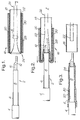
- one end of a single core high voltage cable 2 is schematically shown with its outer insulating, protective jacket 4 cut back to expose its semiconductive screen 6, which has been cut back to expose its dielectric 8, which has been cut back to expose its conductor 10 (shown in broken line), to which a connecting lug 12 has been crimped.
- a delivery arrangement 16 comprises a hollow cylindrical support tube 18 of acrylonitrile butadiene styrene that carries an extruded, radially-stretched electrically insulating elastomeric sleeve 20 of silicone rubber on its outer surface.
- a knitted tubular mesh 22 of high density polyethylene extends along the entire length of the sleeve 20 so as to lie between the tube 18 and the sleeve 20, to pass beyond a front end 24 of the arrangement 16 and thence back through the tube 18 so as to dispose its free end 26 beyond the other end of the arrangement 16.
- the sleeve 20 is shown carrying on its outer surface a first (optional) coating 28 of an insulating sealing mastic towards one end thereof and a second adjacent (optional) coating 30 of a stress control mastic towards the other end thereof.
- the arrangement 16 is used to deliver the coated sleeve 20 on to the end of the cable 2 as follows:
- the tubular arrangement 16 is aligned with the axis of the cable 2 ( Figure 1).
- the arrangement 16 is moved towards the cable 2 such that its front end 24 partially overlaps the cable lug 12.
- the free end 26 of the mesh 22 is pulled through the tube 18 in the direction of the arrow A whilst the adjacent exposed end of the tube 18 is tightly held.
- the mesh 22 slides over the outer surface of the tube 18, carrying with it the radially-tensioned sleeve 20.
- the sleeve 20 may itself be pushed off the tube 18, if the presence of the coatings 28, 30 allows this to be done conveniently. In the latter case, it will be appreciated that the mesh 22 need not extend beyond the length of the sleeve 20.
- the length of the sleeve 20 is such that it completely encloses the exposed lengths of cable screen 6 and dielectric 8, and overlaps at respective ends on to the jacket 4 and lug 12 so as to provide a good seal therewith.
- the sealing of the sleeve 20 on to the cable 2 is enhanced by the, now inner, coatings 28 and 30, and the coating 30 also enhances the control of the electrical stress at the cable cut backs. It will be noted that there is no sliding motion between the sleeve coatings 28, 30 and the underlying cable components during delivery, and that the manner of delivery of the sleeve 22 on to the cable 2 is such as to urge air out from the interface therebetween.
- the mesh tube 22 may be sealed at location B (as shown by dotted outline) within the support tube 18 so as to provide a closed end that can abut the lug 12.
- location B as shown by dotted outline
- the arrangement 16 is then pushed in the opposite direction to the arrow A, and then the engagement of the mesh 22 on the lug 12 effects transfer of the sleeve on to the cable 2.
- the position of the closure seal B is selected with respect to the leading end of the sleeve 20 so as to give the required longitudinal positioning of the sleeve 20 on the cable 2.
- Figure 4 shows an advantageous form of support member for use in the invention, in that it comprises a tubular body 50 having a first portion 52 of its length formed as a cylinder and an adjacent second portion 54 of frusto-conical configuration.
- the internal diameter of the first portion 52 is the minimum diameter necessary for passing over the substrate, for example electric cable, and helps to retain the sleeve (not shown) on the body 50.
- the tapered outer surface of the second portion produces a component of the residual recovery forces in the distended sleeve that acts in the direction of the force applied to remove the sleeve from the support member, thereby reducing the frictional forces between the friction-reducing means (not shown) and the body 50, and thus facilitating delivery of the sleeve.
- Figure 5 shows another advantageous form of support member 60, that has a convoluted cross-section. Since contact with the friction-reducing means (not shown) of the delivery arrangement takes place only over the peaks of the convolutions, the pull-off force is reduced with respect to the tube 18 of the embodiment of Figure 1.
Landscapes
- Non-Metallic Protective Coatings For Printed Circuits (AREA)
- Cable Accessories (AREA)
- Insulating Bodies (AREA)
- Laminated Bodies (AREA)
- Processing Of Terminals (AREA)
- Details Of Indoor Wiring (AREA)
- Media Introduction/Drainage Providing Device (AREA)
- Rigid Pipes And Flexible Pipes (AREA)
Claims (15)
- Procédé de mise en place d'un manchon élastique (20) sur un substrat (2, 42) au moyen d'un agencement (16, 40) de mise en place qui comporte :(i) un élément de support creux (18, 50, 60),(ii) un manchon élastique (20) monté dans une configuration expansée radialement sur l'élément de support (18, 50, 60), et(iii) un moyen solide (22) de réduction de frottement qui est interposé entre le manchon (20) et l'élément de support (18, 50, 60) ;dans lequel (a) l'agencement de mise en place (16, 40) et le substrat (2, 42) sont d'une configuration globalement allongée et sont disposés sensiblement en alignement axial l'un avec l'autre, (b) une première extrémité du manchon (20) est enlevée en glissant de l'élément de support (18, 50, 60) et appliquée, en se retournant, sur le substrat (2, 42) dont elle épouse la forme et, (c) l'élément de support creux (18, 50, 60) est déplacé progressivement le long du substrat (2, 42) jusqu'à ce que la partie restante du manchon (20) soit transférée en se retournant depuis l'élément de support (18, 50, 60) jusque sur le substrat (2, 42).
- Procédé selon la revendication 1, dans lequel le moyen (22) de réduction de frottement s'étend au-delà de ladite première extrémité du manchon (20) et revient en arrière dans l'élément de support (18, 50, 60), et dans lequel le transfert du manchon (20) est facilité par une traction exercée sur le moyen (22) de réduction de frottement dans un sens relativement opposé au mouvement de l'élément (18, 50, 60) de support.
- Procédé selon la revendication 1 ou 2, dans lequel le manchon (20) comporte au moins une couche (28, 30) sur sa surface extérieure avant l'étape de retournement, laquelle couche ou revêtement (28, 30) est placé entre le manchon (20) et le substrat (2, 42) après l'étape de retournement.
- Procédé selon la revendication 3, dans lequel la couche (28, 30) comporte un revêtement de mastic, de matière d'étanchéité, de gel ou de graisse.
- Procédé selon l'une quelconque des revendications précédentes, dans lequel le moyen (22) de réduction de frottement est d'une réalisation maillée.
- Procédé selon l'une quelconque des revendications précédentes, dans lequel le manchon (20) est en matière polymérique et est sensiblement résistant à la formation de traces conductrices par passage de courants de fuite conformément à la norme ASTM D2303.
- Procédé selon l'une quelconque des revendications précédentes, dans lequel le substrat (2, 42) est un composant électrique, avantageusement une zone de terminaison ou de jonction d'un câble de puissance.
- Agencement (16, 40) pour la mise en place d'un manchon élastique (20) sur un substrat (2, 42), l'agencement (16, 40) comportant :(a) un élément de support creux (18, 50, 60), et(b) un moyen solide (22) de réduction de frottement interposé entre le manchon (20) et l'élément de support (18, 50, 60) ; dans lequel(c) le manchon élastique (20) est monté dans une configuration expansée radialement sur l'élément de support (18, 50, 60), et(d) le moyen (22) de réduction de frottement peut être séparé de l'élément de support (18, 50, 60) et du manchon (20) ;grâce à quoi l'application d'un mouvement relatif de glissement entre le manchon (20) et l'élément (18, 50, 60) de support permet de mettre en place le manchon (20) depuis l'élément (18, 50, 60) de support sur le substrat (2, 42) dans une configuration relaxée ; et dans lequel le manchon (20) comporte une couche (28, 30) de matière d'étanchéité, de mastic, de graisse ou de gel sur sa surface extérieure.
- Agencement selon la revendication 8, dans lequel le moyen (22) de réduction de frottement est d'une réalisation maillée.
- Agencement selon la revendication 9, dans lequel la réalisation maillée du moyen (22) de réduction de frottement est conçue pour espacer le manchon (20), sensiblement sur toute sa surface intérieure, de la surface extérieure de l'élément (18, 50, 60) de support.
- Agencement selon l'une quelconque des revendications 8 à 10, dans lequel les matières de l'élément (18, 50, 60) de support et du moyen (22) de réduction de frottement sont telles que la force nécessaire pour extraire le manchon (20) de l'élément (18, 50, 60) de support est inférieure à environ 300 Newtons et est avantageusement inférieure à environ 200 Newtons.
- Agencement selon la revendication 11, dans lequel la matière de l'un du moyen (22) de réduction de frottement et de l'élément (18, 50, 60) de support comprend un composé acrylonitril-butadiène-styrène et l'autre comprend un polyéthylène à haute densité.
- Agencement selon l'une quelconque des revendications 8 à 12, dans lequel le manchon (20) est en matière polymérique et est sensiblement résistant à la formation de traces conductrices par passage de courants de fuite conformément à la norme ASTM D2303.
- Agencement selon l'une quelconque des revendications 8 à 13, dans lequel au moins une partie (54) de l'élément (50) de support présente une configuration globalement tronconique.
- Agencement selon l'une quelconque des revendications 8 à 14, dans lequel au moins une partie de la surface extérieure de l'élément (60) de support est d'une configuration à circonvolutions circonférentielles.
Applications Claiming Priority (3)
| Application Number | Priority Date | Filing Date | Title |
|---|---|---|---|
| GB939307348A GB9307348D0 (en) | 1993-04-07 | 1993-04-07 | Substrate covering |
| GB9307348 | 1993-04-07 | ||
| PCT/GB1994/000731 WO1994023480A1 (fr) | 1993-04-07 | 1994-04-06 | Revetement pour substrats |
Publications (2)
| Publication Number | Publication Date |
|---|---|
| EP0693232A1 EP0693232A1 (fr) | 1996-01-24 |
| EP0693232B1 true EP0693232B1 (fr) | 1997-12-10 |
Family
ID=10733559
Family Applications (1)
| Application Number | Title | Priority Date | Filing Date |
|---|---|---|---|
| EP94912017A Expired - Lifetime EP0693232B1 (fr) | 1993-04-07 | 1994-04-06 | Revetement pour substrats |
Country Status (9)
| Country | Link |
|---|---|
| US (1) | US5735981A (fr) |
| EP (1) | EP0693232B1 (fr) |
| JP (1) | JP3415843B2 (fr) |
| AT (1) | ATE161124T1 (fr) |
| AU (1) | AU694423B2 (fr) |
| CA (1) | CA2160141A1 (fr) |
| DE (1) | DE69407276T2 (fr) |
| GB (1) | GB9307348D0 (fr) |
| WO (1) | WO1994023480A1 (fr) |
Families Citing this family (20)
| Publication number | Priority date | Publication date | Assignee | Title |
|---|---|---|---|---|
| JP3359959B2 (ja) * | 1993-10-21 | 2002-12-24 | ミネソタ マイニング アンド マニュファクチャリング カンパニー | 被覆装置 |
| FR2761830B1 (fr) * | 1997-04-07 | 2000-01-28 | Pirelli Cables Sa | Support de jonction a extraction autonome commandee |
| GB0014643D0 (en) * | 2000-06-16 | 2000-08-09 | Smiths Industries Plc | Methods and assemblies |
| US20050269124A1 (en) * | 2002-07-03 | 2005-12-08 | Shigeru Suzuki | Slidingly detachable core member and cold shrink tube unit having the same |
| CN100448129C (zh) * | 2004-03-23 | 2008-12-31 | 深圳市沃尔核材股份有限公司 | 一种冷缩电缆附件及其制作方法 |
| US20060081393A1 (en) * | 2004-10-14 | 2006-04-20 | Anthony Suzanne T | Modular skirt systems and method of using |
| ATE545976T1 (de) * | 2004-10-27 | 2012-03-15 | Prysmian Spa | Verfahren und einrichtung zur beschichtung des verbindungsbereichs zwischen mindestens zwei länglichen elementen insbesondere zwischen elektrischen kabeln |
| FR2926410B1 (fr) * | 2008-01-16 | 2010-02-19 | D App Et De Materiel Electr S | Ensemble pour recouvrir a enserrement un element allonge avec un manchon elastique de protection |
| CN101814708B (zh) * | 2009-02-19 | 2012-08-29 | 泉州七星电气有限公司 | 一种冷缩型电缆附件的预扩张方法 |
| FR2945675B1 (fr) * | 2009-05-18 | 2011-07-29 | D App Et De Materiel Electr S I C A M E Soc Ind De Const | Ensemble pour recouvrir a enserrement un element allonge de dimensions predeterminees avec un manchon elastique de protection |
| US9136687B2 (en) * | 2011-12-20 | 2015-09-15 | 3M Innovative Properties Company | Low friction sleeve for cold shrink tube |
| DE102013201331B4 (de) * | 2013-01-28 | 2014-12-18 | Leoni Bordnetz-Systeme Gmbh | Elektrische Kontaktverbindung zwischen zwei Elementen, Verfahren zur Ausbildung einer solchen elektrischen Kontaktverbindung sowie Element für eine solche elektrische Kontaktverbindung |
| US9425605B2 (en) | 2013-03-14 | 2016-08-23 | Tyco Electronics Corporation | Method for protecting a cable splice connection with a cover assembly |
| US9178289B2 (en) * | 2013-05-14 | 2015-11-03 | Tyco Electronics Corporation | Joint bodies and methods for covering electrical cables and connections |
| CN104734106B (zh) * | 2013-12-19 | 2018-03-23 | 泰科电子(上海)有限公司 | 将冷缩式终端安装在电力电缆上的方法和冷缩式终端组件 |
| FR3025365B1 (fr) * | 2014-08-27 | 2018-03-30 | Nexans | Dispositif d’installation d’une gaine retractable sur un agencement electrique |
| US9780549B2 (en) | 2015-09-17 | 2017-10-03 | Te Connectivity Corporation | Cover assemblies and methods for covering electrical cables and connections |
| US10389103B2 (en) | 2016-10-18 | 2019-08-20 | Te Connectivity Corporation | Breakout boot assemblies and methods for covering electrical cables and connections |
| EP3734765A1 (fr) | 2019-04-30 | 2020-11-04 | TE Connectivity Germany GmbH | Ensemble de connexion électrique, procédé de connexion électrique d'un conducteur d'un câble à l'aide d'un textile métallique |
| JP2024005488A (ja) * | 2022-06-30 | 2024-01-17 | スリーエム イノベイティブ プロパティズ カンパニー | 被覆処理具、及び被覆処理方法 |
Family Cites Families (15)
| Publication number | Priority date | Publication date | Assignee | Title |
|---|---|---|---|---|
| GB1206654A (en) * | 1967-12-11 | 1970-09-30 | Critchley Bros Ltd | Improvements relating to methods and tools for applying cable markers to electric cables |
| US3992570A (en) * | 1973-12-12 | 1976-11-16 | Amp Incorporated | Cable end sealing devices |
| GB1526397A (en) * | 1974-10-08 | 1978-09-27 | Raychem Ltd | Heat-recoverable article suitable for high voltage use |
| US3946480A (en) * | 1975-04-11 | 1976-03-30 | Communications Technology Corporation | Apparatus for use in applying an expandable resilient sleeve to a member therein |
| SE424386B (sv) * | 1979-10-05 | 1982-07-12 | Kabeldon Ab | Forfarande for att genom paskjutning anbringa en langsmal elastisk kropp med ett langt hal kring en langsmal kerna samt medel for dess genomforande |
| FR2503476B1 (fr) * | 1981-04-01 | 1986-05-02 | Fabrication Cables Elect Cie G | Procede de depose d'une gaine protectrice sur l'extremite d'un cable electrique et dispositif pour la mise en oeuvre de celui-ci |
| US4367105A (en) * | 1981-05-15 | 1983-01-04 | Rosier Lawrence L | Method and apparatus for making elongated articles having sheathed foam insulation |
| SE455658B (sv) * | 1984-07-25 | 1988-07-25 | Kabeldon Ab | Hylsa, avsedd att vendas ut och in vid anbringande |
| US4651505A (en) * | 1985-06-17 | 1987-03-24 | George Gropper | Apparatus and method of making cleaning pads |
| FR2592825B1 (fr) * | 1986-01-13 | 1988-03-11 | Artema | Manchon auxiliaire de positionnement, dispositif dote d'un tel manchon et procede de positionnement correspondant |
| IT1236543B (it) * | 1989-10-11 | 1993-03-11 | Ubaldo Vallauri | Elemento immagazzinabile di rivestimento di giunti di cavi elettrici, applicabile a piu' cavi di differente diametro, con strato interno a bassa deformazione residua. |
| US5171940A (en) * | 1989-10-11 | 1992-12-15 | Societa' Cavi Pirelli S.P.A. | Expanded cable joint elastic sleeves with permissible residual deformation after storage |
| US5229176A (en) * | 1991-06-04 | 1993-07-20 | Minnesota Mining And Manufacturing Company | Protective sleeve and method of assembling the protective sleeve to an object to be protected |
| FR2706979B1 (fr) * | 1993-06-25 | 1995-09-22 | Euromold | |
| JP3359959B2 (ja) * | 1993-10-21 | 2002-12-24 | ミネソタ マイニング アンド マニュファクチャリング カンパニー | 被覆装置 |
-
1993
- 1993-04-07 GB GB939307348A patent/GB9307348D0/en active Pending
-
1994
- 1994-04-06 AU AU64338/94A patent/AU694423B2/en not_active Ceased
- 1994-04-06 CA CA002160141A patent/CA2160141A1/fr not_active Abandoned
- 1994-04-06 JP JP52187694A patent/JP3415843B2/ja not_active Expired - Fee Related
- 1994-04-06 DE DE69407276T patent/DE69407276T2/de not_active Expired - Fee Related
- 1994-04-06 EP EP94912017A patent/EP0693232B1/fr not_active Expired - Lifetime
- 1994-04-06 WO PCT/GB1994/000731 patent/WO1994023480A1/fr not_active Ceased
- 1994-04-06 AT AT94912017T patent/ATE161124T1/de not_active IP Right Cessation
- 1994-04-06 US US08/537,651 patent/US5735981A/en not_active Expired - Fee Related
Also Published As
| Publication number | Publication date |
|---|---|
| DE69407276D1 (de) | 1998-01-22 |
| JPH08508633A (ja) | 1996-09-10 |
| AU694423B2 (en) | 1998-07-23 |
| WO1994023480A1 (fr) | 1994-10-13 |
| ATE161124T1 (de) | 1997-12-15 |
| US5735981A (en) | 1998-04-07 |
| CA2160141A1 (fr) | 1994-10-13 |
| EP0693232A1 (fr) | 1996-01-24 |
| DE69407276T2 (de) | 1998-07-16 |
| JP3415843B2 (ja) | 2003-06-09 |
| GB9307348D0 (en) | 1993-06-02 |
| AU6433894A (en) | 1994-10-24 |
Similar Documents
| Publication | Publication Date | Title |
|---|---|---|
| US5735981A (en) | Substrate covering | |
| EP0947038B1 (fr) | Dispositif de gaine pour des cables | |
| AU653520B2 (en) | Cold recoverable elastomeric sleeve and method for installation and use | |
| CA2186824C (fr) | Machine a enrober a noyau rigide | |
| US4289553A (en) | Heat-shrinkable article | |
| CN103999307B (zh) | 用于冷缩管的低摩擦套管 | |
| AU668521B2 (en) | Enclosure assembly for use over elongate cylindrical objects such as electric cable splices | |
| AU730552B2 (en) | Power cable joint device | |
| EP0518560B1 (fr) | Douille protectrice et procédé d'assembler cette douille protectrice sur un objet à être protégé | |
| CA2280848C (fr) | Dispositif couvrant compact | |
| JPH11502399A (ja) | さや状の弾性的なケーブルスリーブをケーブル接続部に嵌め込んで位置決めする方法と装置 | |
| US10734797B2 (en) | Cover assemblies for cables and electrical connections and pre-expanded units and methods including same | |
| JP2516636B2 (ja) | ケ−ブル接続部等の防水型筒状部材 | |
| HK1024568B (en) | Compact covering device | |
| JPS62211878A (ja) | 弾性自己収縮性チユ−ブ |
Legal Events
| Date | Code | Title | Description |
|---|---|---|---|
| PUAI | Public reference made under article 153(3) epc to a published international application that has entered the european phase |
Free format text: ORIGINAL CODE: 0009012 |
|
| 17P | Request for examination filed |
Effective date: 19951005 |
|
| AK | Designated contracting states |
Kind code of ref document: A1 Designated state(s): AT BE CH DE DK ES FR GB IT LI NL SE |
|
| 17Q | First examination report despatched |
Effective date: 19960119 |
|
| GRAG | Despatch of communication of intention to grant |
Free format text: ORIGINAL CODE: EPIDOS AGRA |
|
| GRAG | Despatch of communication of intention to grant |
Free format text: ORIGINAL CODE: EPIDOS AGRA |
|
| GRAH | Despatch of communication of intention to grant a patent |
Free format text: ORIGINAL CODE: EPIDOS IGRA |
|
| GRAH | Despatch of communication of intention to grant a patent |
Free format text: ORIGINAL CODE: EPIDOS IGRA |
|
| GRAA | (expected) grant |
Free format text: ORIGINAL CODE: 0009210 |
|
| AK | Designated contracting states |
Kind code of ref document: B1 Designated state(s): AT BE CH DE DK ES FR GB IT LI NL SE |
|
| PG25 | Lapsed in a contracting state [announced via postgrant information from national office to epo] |
Ref country code: NL Free format text: LAPSE BECAUSE OF FAILURE TO SUBMIT A TRANSLATION OF THE DESCRIPTION OR TO PAY THE FEE WITHIN THE PRESCRIBED TIME-LIMIT Effective date: 19971210 Ref country code: LI Free format text: LAPSE BECAUSE OF FAILURE TO SUBMIT A TRANSLATION OF THE DESCRIPTION OR TO PAY THE FEE WITHIN THE PRESCRIBED TIME-LIMIT Effective date: 19971210 Ref country code: IT Free format text: LAPSE BECAUSE OF FAILURE TO SUBMIT A TRANSLATION OF THE DESCRIPTION OR TO PAY THE FEE WITHIN THE PRESCRIBED TIME-LIMIT;WARNING: LAPSES OF ITALIAN PATENTS WITH EFFECTIVE DATE BEFORE 2007 MAY HAVE OCCURRED AT ANY TIME BEFORE 2007. THE CORRECT EFFECTIVE DATE MAY BE DIFFERENT FROM THE ONE RECORDED. Effective date: 19971210 Ref country code: ES Free format text: THE PATENT HAS BEEN ANNULLED BY A DECISION OF A NATIONAL AUTHORITY Effective date: 19971210 Ref country code: DK Free format text: LAPSE BECAUSE OF NON-PAYMENT OF DUE FEES Effective date: 19971210 Ref country code: CH Free format text: LAPSE BECAUSE OF FAILURE TO SUBMIT A TRANSLATION OF THE DESCRIPTION OR TO PAY THE FEE WITHIN THE PRESCRIBED TIME-LIMIT Effective date: 19971210 Ref country code: BE Free format text: LAPSE BECAUSE OF FAILURE TO SUBMIT A TRANSLATION OF THE DESCRIPTION OR TO PAY THE FEE WITHIN THE PRESCRIBED TIME-LIMIT Effective date: 19971210 Ref country code: AT Free format text: LAPSE BECAUSE OF FAILURE TO SUBMIT A TRANSLATION OF THE DESCRIPTION OR TO PAY THE FEE WITHIN THE PRESCRIBED TIME-LIMIT Effective date: 19971210 |
|
| REF | Corresponds to: |
Ref document number: 161124 Country of ref document: AT Date of ref document: 19971215 Kind code of ref document: T |
|
| REG | Reference to a national code |
Ref country code: CH Ref legal event code: EP |
|
| REF | Corresponds to: |
Ref document number: 69407276 Country of ref document: DE Date of ref document: 19980122 |
|
| ET | Fr: translation filed | ||
| PG25 | Lapsed in a contracting state [announced via postgrant information from national office to epo] |
Ref country code: SE Free format text: LAPSE BECAUSE OF FAILURE TO SUBMIT A TRANSLATION OF THE DESCRIPTION OR TO PAY THE FEE WITHIN THE PRESCRIBED TIME-LIMIT Effective date: 19980310 |
|
| NLV1 | Nl: lapsed or annulled due to failure to fulfill the requirements of art. 29p and 29m of the patents act | ||
| REG | Reference to a national code |
Ref country code: CH Ref legal event code: PL |
|
| PLBE | No opposition filed within time limit |
Free format text: ORIGINAL CODE: 0009261 |
|
| STAA | Information on the status of an ep patent application or granted ep patent |
Free format text: STATUS: NO OPPOSITION FILED WITHIN TIME LIMIT |
|
| 26N | No opposition filed | ||
| REG | Reference to a national code |
Ref country code: GB Ref legal event code: IF02 |
|
| PGFP | Annual fee paid to national office [announced via postgrant information from national office to epo] |
Ref country code: GB Payment date: 20050330 Year of fee payment: 12 |
|
| PGFP | Annual fee paid to national office [announced via postgrant information from national office to epo] |
Ref country code: FR Payment date: 20050418 Year of fee payment: 12 |
|
| PGFP | Annual fee paid to national office [announced via postgrant information from national office to epo] |
Ref country code: DE Payment date: 20050531 Year of fee payment: 12 |
|
| PG25 | Lapsed in a contracting state [announced via postgrant information from national office to epo] |
Ref country code: GB Free format text: LAPSE BECAUSE OF NON-PAYMENT OF DUE FEES Effective date: 20060406 |
|
| PG25 | Lapsed in a contracting state [announced via postgrant information from national office to epo] |
Ref country code: DE Free format text: LAPSE BECAUSE OF NON-PAYMENT OF DUE FEES Effective date: 20061101 |
|
| GBPC | Gb: european patent ceased through non-payment of renewal fee |
Effective date: 20060406 |
|
| REG | Reference to a national code |
Ref country code: FR Ref legal event code: ST Effective date: 20061230 |
|
| PG25 | Lapsed in a contracting state [announced via postgrant information from national office to epo] |
Ref country code: FR Free format text: LAPSE BECAUSE OF NON-PAYMENT OF DUE FEES Effective date: 20060502 |